| AAM | advanced air mobility |
| AC | Advisory Circular |
| AC | alternating current |
| ADA | Americans with Disabilities Act |
| ALP | Airport Layout Plan |
| AWOS | automated weather observing system |
| CCS | combined charging standard |
| CD | candela |
| CFR | Code of Federal Regulations |
| D | controlling dimension |
| DC | direct current |
| DCA | downwash/outwash caution area |
| DER | distributed energy resource |
| DWOW | Downwash/Outwash |
| EB | Engineering Brief |
| EMS | Emergency Medical Service |
| ESS | energy storage system |
| ETL | effective translational lift |
| EV | electric vehicle |
| EVSE | electric vehicle supply equipment |
| eVTOL | electric vertical takeoff and landing |
| FAA | Federal Aviation Administration |
| FATO | final approach and takeoff area |
| FC | failure condition |
| FOD | foreign object debris |
| GSE | ground service equipment |
| GVGI | generic visual glideslope indicators |
| HOGE | hover out of ground eff ect |
| IEC | International Electrotechnical Commission |
| IEEE | Institute of Electrical and Electronics Engineers |
| IFC | International Fire Code |
| IFR | instrument flight rules |
| IMC | instrument meteorological conditions |
| ISO | International Organization for Standardization |
| kph | kilometers per hour |
| kWh | kilowatt per hour |
| LAP | Landing Area Proposal |
| LBA | load-bearing area |
| LED | light emitting diode |
| LOB | line of business |
| MCS | megawatt charging system |
| mJ | millijoule |
| MSL | mean sea level |
| MTOW | maximum takeoff weight |
| MW | megawatt |
| MWh | megawatt per hour |
| NAS | National Airspace System |
| NEC | National Electric Code |
| NEPA | National Environmental Policy Act |
| NEMSPA | National EMS Pilots Association |
| NFPA | National Fire Protection Association |
| NREL | National Renewable Energy Laboratory |
| OEM | original equipment manufacturer |
| OFA | object free area |
| PAPI | precision approach path indicator |
| PPR | prior permission required |
| R&D | Research and Development |
| RD | Rotor diameter |
| RNAV | Area Navigation |
| SAE | SAE International |
| TDPC | touchdown/positioning circle |
| TLOF | touchdown and liftoff area |
| UL | Underwriters Laboratories |
| VFR | visual flight rules |
VGSI Visual Glideslope Indicator VMC visual meteorological conditions VTOL vertical takeoff and landing
# FAA AC 150/5390-2D Heliport Design
Subject: Heliport Design
Date: 1/5/2023
Initiated By: AAS-100
AC No: 150/5390-2D
Change:
1 Purpose.
This advisory circular (AC) provides standards for the planning, design and construction of heliports serving helicopters with single, tandem (front and rear) or dual (side by side) rotors.
2 Cancellation.
This AC cancels AC 150/5390-2C, Heliport Design, dated April 24, 2012.
3 Applicability.
The Federal Aviation Administration (FAA) recommends the standards and guidelines in this AC for uniformity in planning, design, and construction of heliports. This AC does not constitute a regulation, is not mandatory and is not legally binding in its own right. This AC will not be relied upon as a separate basis by the FAA for affirmative enforcement action or other administrative penalty. The standards and guidelines contained in this AC are practices the FAA recommends for establishing an acceptable level of safety, performance, and operation for heliports. Conformity with this AC is voluntary, except for the projects described in subparagraphs 1, 2, and 3 below:
Use of these standards and guidelines is mandatory for projects funded under Federal grant assistance programs, including but not limited to the Airport Improvement Program (AIP) and Coronavirus Aid, Relief, and Economic Security (CARES) Act Airport Grants program. See Grant Assurance #34. Heliport sponsors should familiarize themselves with the obligations and assurances that apply to each grant program from which they obtained grant funds.
This AC is mandatory, as required by regulation, for projects funded by the Passenger Facility Charge (PFC) program. See PFC Assurance #9.
This AC has no applicability under Title 14 Code of the Federal Regulations (CFR) Part 139 due to an exemption for heliport operators per § 139.1(c)(5).
Other federal agencies, states, or other authorities having jurisdiction over the construction of heliports not funded with AIP, CARES Act, or PFC funds have discretion in establishing the extent to which these standards apply.
## 4 Related Documents.
ACs and Orders referenced in the text of this AC do not include a revision letter, as they refer to the latest version. See Appendix E for a list of associated publications.
## 5 Principal Changes.
The AC incorporates the following principal changes:
Complete reorganization of this AC:
a. Consolidated Chapters 2, 3 and 4 (GENERAL AVIATION, TRANSPORT, and HOSPITAL heliport chapters, respectively) into Chapter 2.
b. Consolidated Chapter 7 (Heliport Gradients and Pavement Design) into Chapter 2.
c. Included a separate Chapter 3 on Heliport Taxiways, Taxi Routes, and Helicopter Parking.
d. Included a separate Chapter 4 on Heliport Markings and Lighting.
e. Included a separate Chapter 7 on Heliport Site Safety Elements.
f. Added new Appendix B, Pre-designated Emergency Landing Areas (PELAs).
g. Incorporated Engineering Brief #87, Heliport Perimeter Light for Visual Meteorological Conditions, into this AC to address specific heliport lighting requirements. Heliport lighting design requirements are included in Appendix G.
Revised figures and tables to correspond with the design requirements and dimensions for GENERAL AVIATION, TRANSPORT, and HOSPITAL heliports.
Enhanced the figures to include dimensional, layout, and offset requirements.
Updated the format of the document and made minor editorial changes throughout.
Included a heliport evaluation process flow chart in Appendix F.
## 6 Using this Document.
Hyperlinks (allowing the reader to access documents located on the internet and to maneuver within this document) are provided throughout this document and are identified with underlined text. When navigating within this document, return to the previously viewed page by pressing the “ALT” and “ ←” keys simultaneously.
Figures in this document are general representations and are not to scale. Colors and shading used in the figures are illustrative only. Guidance on specific heliport markings is provided in Chapter 4.
## 7 Use of Metrics.
Throughout this AC, U.S. customary units are used followed with “soft” (rounded) conversion to metric units. The U.S. customary units govern.
## 8 Where to Find this AC.
You can view a list of all ACs at
https://www.faa.gov/regulations\_policies/advisory\_circulars/. You can view the Federal Aviation Regulations at https://www.faa.gov/regulations\_policies/faa\_regulations/.
## 9 Feedback on this AC.
If you have suggestions for improving this AC, you may use the Advisory Circular Feedback form at the end of this AC.

John R. Dermody
Director of Airport Safety and Standards
## CONTENTS
Paragraph Page
CHAPTER 1. Introduction.. .... 1-1
1.1 Background.. ..... 1-1
1.2 General... .... 1-1
1.3 Facilities. . .... 1-1
1.4 Planning. ... .... 1-2
1.5 Existing Heliports. ..... ..... 1-2
1.6 Location. ............. ...................... 1-2
1.7 AC Organization. ........ ....... 1-3
1.8 Explanation of Terms...... ....... 1-3
1.9 Selection of Approach/Departure Paths.. ... 1-10
1.10 Notification Requirements. .. ..... 1-10
1.11 Hazards to Air Navigation. . .... 1-15
1.12 Federal Assistance. . ... 1-18
1.13 Environmental Impact Analyses.. ... 1-18
1.14 Terminal Facilities Design Considerations.. ..... 1-19
1.15 Zoning for Compatible Land Use. ...... ................. 1-19
1.16 Access to Heliports by Individuals with Disabilities..... ....... 1-20
1.17 State Role. ... ..... 1-20
1.18 Local Role and Building Code.. ... 1-20
1.19 Related Referenced Material.. .... 1-20
CHAPTER 2. Heliport Design... ..... 2-1
2.1 General... .... 2-1
2.2 Prior Permission Required (PPR) Facilities........... ........ 2-1
2.3 Design Approach. ..... .... 2-1
2.4 Access by Individuals with Disabilities.. ..... 2-1
2.5 Heliport Site Selection. . ... 2-4
2.6 TLOF/FATO and Safety Area Relationships. ..... 2-7
2.7 Touchdown and Liftoff Area (TLOF).. ... 2-9
2.8 Final Approach and Takeoff Area (FATO). .. 2-17
## CONTENTS
Paragraph Page
2.9 Safety Area.. .. 2-21
2.10 Fall Protection and Safety Net Design.. ... 2-24
2.11 Pavement Design and Soil Stabilization. . ... 2-25
2.12 VFR Approach/Departure Paths. . .. 2-27
2.13 Heliport Protection Zone (HPZ). . .. 2-35
2.14 Wind Cone. . ... 2-35
CHAPTER 3. Heliport Taxiways, Taxi Routes, and Helicopter Parking ...... ...... 3-1
3.1 General.. .... 3-1
3.2 Taxiways and Taxi Routes....... ........ 3-1
3.3 Taxiway/Taxi Route Widths..... ...... 3-1
3.4 Taxiway Surfaces.... ..... 3-6
3.5 Taxiway and Taxi Route Gradients. ... 3-6
3.6 Helicopter Parking. . .... 3-6
3.7 Parking Position Sizes.... .... 3-13
3.8 Walkways.... ... 3-16
3.9 Fueling. ........ ... 3-16
3.10 Tiedowns.... ... 3-16
CHAPTER 4. Heliport Markings and Lighting...... ......... 4-1
4.1 General.. .... 4-1
4.2 Heliport Retroreflective Markers and Markings. .... 4-1
4.3 Standard Heliport Identification Marking... ..... 4-1
4.4 TLOF and FATO Markings.. ..... 4-6
4.5 Extended Pavement/Structure Markings for GENERAL AVIATION and
HOSPITAL Heliports. ..... .... 4-10
4.6 FATO Perimeter Markings. .... ................ ..... 4-10
4.7 Flight Path Alignment Guidance Marking.. ... 4-11
4.8 Taxiway and Taxi Route Markings..... ........................................................... 4-12
4.9 Helicopter Parking Position Markings.. ...... 4-13
4.10 Walkways..... ... 4-14
4.11 Closed Heliport. . .. 4-14
## CONTENTS
Paragraph Page
4.12 Marking Sizes. .. ... 4-15
4.13 Heliport Lighting. . .. 4-15
CHAPTER 5. Helicopter Facilities on Airports... ..... 5-1
5.1 General.. .... 5-1
5.2 Touchdown and Liftoff Area (TLOF). ... 5-1
5.3 On-Airport Location of Final Approach and Takeoff Area (FATO). ... 5-1
5.4 Safety Area..... ...... 5-3
5.5 VFR Approach/Departure Paths. .. .... 5-3
5.6 Heliport Protection Zone (HPZ). ... 5-3
5.7 Taxiways and Taxi Routes..... ... 5-3
5.8 Helicopter Parking. . .. 5-4
5.9 Security. .. .. 5-4
CHAPTER 6. Instrument Operations .... ..... 6-1
6.1 General.. ... 6-1
6.2 Planning. ... ... 6-3
6.3 Airspace. .. ... 6-3
6.4 Final Approach Reference Area (FARA). .. ...... 6-3
6.5 Improved Instrument Lighting System. ... ..... 6-4
6.6 Obstacle Evaluation Surfaces. .... 6-8
6.7 Visual Glideslope Indicators (VGSI)... ..... 6-8
CHAPTER 7. Heliport Site Safety Elements ... ..... 7-1
7.1 General.... ..... 7-1
7.2 Marking and Lighting of Difficult-To-See Objects.. ..... 7-1
7.3 Safety Considerations. . ... 7-4
Appendix A. Emergency Helicopter Landing Facilities (EHLF)..... ..... A-1
A.1 General... .. A-1
A.2 Notification and Coordination. .. ... A-1
A.3 Rooftop Emergency Facilities.. .. A-1
## CONTENTS
Paragraph Page
Appendix B. Pre-designated Emergency Landing Areas (PELAs) ..... ..B-1
Appendix C. Helicopter Data... .... C-1
Appendix D. Dimensions for Marking Size and Weight Limitations............... . D-1
Appendix E. Associated Publications and Resources ...... .....E-1
Appendix F. Heliport Evaluation Process Flow Chart ... .....F-1
Appendix G. Design Requirements for Heliport Perimeter Lighting ..... ..... G-1
G.1 Elevated and In-pavement Omnidirectional Helipad Perimeter Light. ... G-1
G.2 Photometric Requirements.. .. G-2
G.3 Additional Heliport Perimeter Light Requirements.. .. G-2
G.4 L-860H and L-852H Light Fixture Testing. ... .. G-3
G.5 Installation Criteria. .. .. G-3
## FIGURES
Figure 1-1. FAA Form 7480-1, Notice for Construction, Alteration and Deactivation of Airports
... 1-12
Figure 1-2. Example of a Heliport Layout Plan.. .... 1-13
Figure 1-3. Example of a Heliport Location Map... ..... 1-14
Figure 1-4. Offsite Development Requiring Notice to the FAA . ... 1-17
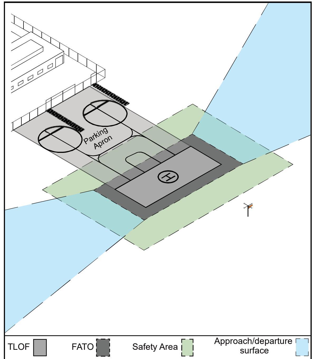
Figure 2-1. GENERAL AVIATION Heliport – Basic Features... ... 2-2
Figure 2-2. TRANSPORT Heliport – Basic Features...... ..... 2-3
Figure 2-3. HOSPITAL Heliport (Ground Level) – Basic Features.. .. 2-4
Figure 2-4. Heliport EMI Hazard Marking.. .. 2-6
Figure 2-5. Heliport EMI Hazard Sign .... .. 2-7
Figure 2-6. TLOF/FATO/Safety Area Relationships and Minimum Dimensions . .. 2-8
Figure 2-7. Heliport Gradients and Rapid Runoff Shoulder - Load-bearing FATOs. ... 2-12
Figure 2-8. Optional Elongated TLOF and FATO with Two Takeoff Positions.. ... 2-13
Figure 2-9. Elevated Heliport: GENERAL AVIATION and HOSPITAL. ... 2-15
Figure 2-10. Elevated Heliport: TRANSPORT . .... 2-16
Figure 2-11. Additional FATO Length for Heliports at Higher Elevations .. ... 2-19
Figure 2-12. Non-load-bearing FATO and Safety Area over Water: GENERAL AVIATION and
HOSPITAL Heliports .. ... 2-23
Figure 2-13. Non-load-bearing Safety Area over Water: TRANSPORT ... ... 2-24
Figure 2-14. Helicopter Landing Gear Loading: Gradients and Pavement ..... ..... 2-26
Figure 2-15. VFR Heliport Approach/Departure and Transitional Surfaces. .. 2-28
Figure 2-16. VFR Curved Approach/Departure and Transitional Surfaces – GENERAL
AVIATION and TRANSPORT Heliports. .. 2-29
Figure 2-17. VFR HOSPTIAL and PPR Heliport Optional Lateral Extensions of the 8:1
Approach/Departure Surface .. 2-31
Figure 2-18. VFR HOSPITAL and PPR Heliport Optional Lateral Extension of the Curved 8:1
Approach/Departure Surface . ... 2-33
Figure 2-19. Flight Path Alignment Marking and Lights ... ... 2-34
Figure 2-20. Heliport Protection Zone (HPZ).. ... 2-36
Figure 3-1. Taxiway/Taxi Route Relationship – Paved Taxiway.. .. 3-2
Figure 3-2. Taxiway/Taxi Route Relationship – Unpaved Taxiway with Elevated Retroreflective
Edge Markers .... .. 3-3
Figure 3-3. Taxiway/Taxi Route Relationship – Unpaved Taxiway with In-Pavement
Retroreflective Edge Markers ........ ...... 3-4
Figure 3-4. Hover Taxi Area.. ... 3-5
Figure 3-5. Typical Parking Area Design – “Taxi-through” Parking Positions. ............ ........ 3-7
Figure 3-6. Typical Parking Area Design – “Turn-around” Parking Positions ....... ...... 3-8
Figure 3-7. Typical Parking Area Design – “Back-out” Parking Positions.. .... 3-9
Figure 3-8. “Turn-around” Parking Position Marking.. .. 3-11
Figure 3-9. “Taxi-through” and “Back-out” Parking Position Marking.. .. 3-12
Figure 3-10. Parking Position Identification, Size, and Weight Limitations – Paved Areas, Turn-
Around Parking...... ..... 3-14
Figure 3-11. Parking Position Identification, Size, and Weight Limitations – Paved Areas, “Taxi
through” and “Back-out” Parking........ ........ 3-15
Figure 4-1. Standard TLOF Markings ..... .... 4-3
Figure 4-2. Standard Heliport Identification Symbol, TLOF Size and Weight Limitations ....... 4-4
Figure 4-3. HOSPITAL Heliport – Standard Identification Marking.. .... 4-5
Figure 4-4. HOSPITAL Heliport – Alternative Identification Marking.. .... 4-6
Figure 4-5. Paved TLOF/Paved FATO – Paved TLOF/Unpaved FATO – Marking:
TRANSPORT Heliports and Other Heliports with a Paved TLOF...... ...... 4-7
Figure 4-6. Unpaved TLOF/Unpaved FATO – Marking: GENERAL AVIATION and
HOSPITAL Heliports ... .... 4-8
Figure 4-7. Extended Pavement/Structure Marking: GENERAL AVIATION and HOSPITAL
Heliports.. ... 4-11
Figure 4-8. Marking a Closed Heliport... ................................... ...... 4-15
Figure 4-9. Elevated TLOF – Perimeter Lighting ...... .................................. ..... ...... 4-17
Figure 4-10. TLOF/FATO Perimeter Lighting...... ................ .... 4-18
Figure 4-11. TLOF In-pavement and FATO Elevated Perimeter Lighting . .... 4-19
Figure 4-12. FATO Elevation.. .... 4-21
Figure 4-13. Landing Direction Lights. .. 4-23
Figure 5-1. Example of Heliport Facilities Located on an Airport.. .. 5-2
Figure 6-1. FARA/FATO Relationship: Precision Instrument Procedure...... ....... 6-4
Figure 6-2. Heliport Instrument Lighting System (HILS): Non-precision .... ....... 6-6
Figure 6-3. Heliport Approach Lighting System ... ....... 6-7
Figure 6-4. Visual Glideslope Indicator (VGSI) Siting and Clearance Criteria .......................... 6-9
Figure 7-1. Airspace Where Heliport Marking and Lighting are Recommended: Straight
Approach.. ... 7-2
Figure 7-2. Airspace Where Heliport Marking and Lighting are Recommended: Curved
Approach.. .. 7-3
Figure 7-3. Heliport Caution Sign . .. 7-5
Figure A-1. Rooftop Emergency Landing Facility.. . A-2
Figure C-1. Helicopter Dimensions ... . C-2
Figure D-1. Form and Proportions of 36-inch (0.9 m) Numbers for Marking Size and Weight
Limitations . . D-2
Figure D-2. Form and Proportions of 18-inch (0.5 m) Numbers for Marking Size and Weight
Limitation. . D-3
Figure G-1. Perimeter Light Intensity Distribution ... . G-2
## TABLES
Table 2-1. TLOF/FATO Minimum Dimensions 1 .. 2-8
Table 2-2. Minimum Dimensions for Elongated FATO with Two Takeoff Positions.... .. 2-13
Table 2-3. TLOF Elevation and Configuration of Rooftop and other Elevated Heliports ........ 2-14
Table 2-4. Minimum VFR Safety Area Width as a Function of Heliport Markings GENERAL
AVIATION, HOSPITAL, and PPR Heliports... ... 2-21
Table 2-5. Differences in Safety Net Design for Rooftop and Elevated Heliports.. .. 2-25
Table 3-1. Taxiway/Taxi Route Dimensions – GENERAL AVIATION, TRANSPORT, and
HOSPITAL Heliports .. .. 3-5
Table 4-1. FATO Perimeter Light Design .. ... 4-20
Table 5-1. Recommended Distance between FATO Center to Runway Centerline for VFR
Operations .. .. 5-3
Table 6-1. Standards for Instrument Approach Procedures. .. 6-2
Table C-1. Helicopter Data . . C-3
Table G-1. Helicopter Approach Angles Assuming VMC. . G-1
Table G-2. Perimeter Lighting Intensity Recommendations .. . G-2
# CHAPTER 1. Introduction
## 1.1 Background.
Section 103 of the Federal Aviation Act of 1958 states in part, “In the exercise and performance of his power and duties under this Act, the Secretary of Transportation shall consider the following, among other things, as being in the public interest: (a) The regulation of air commerce in such manner as to best promote its development and safety and fulfill the requirements of defense; (b) The promotion, encouragement, and development of civil aeronautics . . .” This public charge, in effect, requires the development and maintenance of a national system of safe heliports. Using the standards and recommendations contained in this publication in the design of heliports supports this public charge.
These standards and recommendations do not limit or regulate the operations of helicopters, aircraft or heliports. When it is not feasible to meet the standards and recommendations in this advisory circular (AC), consult with the appropriate offices of the Federal Aviation Administration (FAA) Office of Airports and Flight Standards Service to identify possible adjustments to include operational procedures that accommodate safe heliport operations to the maximum extent.
The guidance provided in this AC is limited to heliports and helicopter operations. This AC does not specifically consider the characteristics of all vertical takeoff and landing (VTOL) aircraft or unmanned aircraft. New aircraft entrants that have an interest in operating at heliports should work with the FAA Office of Airports and Flight Standards to demonstrate that their aircraft’s operational and safety parameters comply with this AC, prior to operations.
The FAA is developing guidance for vertiports that would be intended for VTOL and/or unmanned aircraft. Until that guidance is published, entities developing operating sites for new aircraft entrants are encouraged to work with the FAA Office of Airports and Flight Standards on applicable design, operational, and safety criteria tailored to the performance of aircraft which intend to operate at those facilities.
## 1.2 General.
This chapter provides:
an explanation of terms used in this AC,
• notification responsibilities of heliport proponents to the FAA,
general heliport siting guidance, and
sources of technical information relating to the planning and design of a civil heliport.
## 1.3 Facilities.
Most heliports are not large and elaborate. A minimal facility may be adequate as a private-use prior permission required (PPR) heliport (see Appendix A) and may serve as the initial phase in the development of a public-use heliport capable of serving the
general aviation segment of the helicopter community. See Chapter 2 for requirements and design guidance for each specific heliport type.
The basic elements of a heliport include:
clear approach/departure paths,
• clear area for ground maneuvers,
• final approach and takeoff area (FATO),
• touchdown and liftoff area (TLOF),
safety area, and
a wind cone.
## 1.4 Planning.
This AC is a design document intended to assist engineers, architects, and city planners to design, locate, and build a suitable heliport. While the heliport itself may be simple, the planning and organization necessary to properly develop a heliport can present challenges. Ensure proper consideration of the physical, technical, safety, and public interest matters described in this document during the planning and establishment of a heliport.
## 1.5 Existing Heliports.
Whenever a change or alteration to an existing heliport requires the submission of FAA Form 7460-1, Notice of Proposed Construction or Alteration, or FAA Form 7480-1, Notice of Landing Area Proposal, consider taking necessary actions, as practical, to bring the heliport up to current design standards. Refer to paragraph 1.11.3 for additional information.
## 1.6 Location.
The optimum location for a heliport is near the desired origination and/or destination of the potential heliport users. Industrial, commercial, and medical operations in urban locations are demand generators for helicopter services, even though they often compete for the limited ground space available.
## 1.6.1 Factors to Consider.
Heliport sites adjacent to a river, lake, railroad, freeway, or highway offer potential for multi-functional land usage.
Locations that have the advantage of unobstructed airspace and which have properly enacted zoning can provide further protection from disruptive encroachment.
Requirements for scheduled “airline-type” passenger services may necessitate the development of an instrument procedure to permit “all-weather” service.
## 1.7 AC Organization.
This AC covers GENERAL AVIATION heliports (including PPR heliports), TRANSPORT heliports, HOSPITAL heliports, and emergency landing facilities. Heliport proponent familiarity with the terminology used in this specialized field is imperative. See paragraph 1.8 for specific heliport terminology and definitions.
## 1.7.1 Helicopter Facilities on Airports.
Consider developing separate heliport facilities for helicopter use when there are a significant number of helicopter operations on an airport. Chapter 5 addresses helicopter facilities on airports.
## 1.7.2 Instrument Operations.
Instrument approach procedures at heliports are practical since the introduction of the global positioning system (GPS). Good planning suggests that heliport proponents plan for the eventual development of instrument approaches to their heliports. Consider the recommendations in Chapter 6 in contemplating future instrument operations at a heliport during heliport site selection and design, even if the heliport will not initially have instrument operations.
## 1.7.3 Heliport Gradients and Pavement Design.
Chapter 2 provides guidance on heliport gradients and pavement design issues.
## 1.7.4 Additional Information and Resources.
Additional information and resources are found in the Appendices as follows:
• Appendix A provides guidance on emergency helicopter landing facilities.
• Appendix B provides guidance for pre-designated emergency landing areas.
Appendix C provides helicopter dimensional data.
Appendix D provides guidance on the form, size, and proportions of certain heliport markings.
Appendix E provides a list of associated publications and resources referenced in this AC.
• Appendix F provides a heliport evaluation process flow chart.
Appendix G provides design guidance on heliport lighting.
## 1.8 Explanation of Terms.
The Pilot/Controller Glossary of the Aeronautical Information Manual (AIM) defines terms used in the Air Traffic System. Copies of the AIM are available from the FAA website https://www.faa.gov/air\_traffic/publications/. Other terms used in this publication follow.
## 1.8.1 Air Taxi.
Refers to helicopter taxi operations, typically below 100 feet (30.5 m) above ground level (AGL), which allows helicopter movement from one point to another.
## 1.8.2 Approach/Departure Path.
## 1.8.3 Controlling Dimension (D).
The greater of helicopter overall length (OL) and overall width (OW).
## 1.8.4 Design Helicopter.
A single or composite helicopter that reflects the maximum weight, maximum contact load/minimum contact area, controlling dimension (D), overall width (OW), rotor diameter (RD), tail rotor arc radius, undercarriage dimensions, and pilot’s eye height of all helicopters expected to operate at the heliport.
## 1.8.5 Design Loads.
Design and construct the touchdown and lift area (TLOF), and any load-bearing surfaces, to support the loads imposed by the design helicopter and any ground support vehicles and equipment.
## 1.8.5.1 Static Load.
For design purposes, the design static load is equal to the helicopter’s maximum takeoff weight applied through the total contact area of the wheels or skids. See paragraph 2.7.3.1.
## 1.8.5.2 Dynamic Load.
For design purposes, assume the dynamic load at 150 percent of the maximum takeoff weight of the design helicopter applied through the main undercarriage on a wheel-equipped helicopter or aft contact areas of skidequipped helicopter. See paragraph 2.7.3.2.
## 1.8.6 Elevated Heliport.
A heliport located on a rooftop or other elevated structure where the TLOF is at least 30 inches (0.8 m) above the surrounding surface (a ground-level heliport with the TLOF on a mound is not an elevated heliport).
## 1.8.7 Emergency Helicopter Landing Facility (EHLF).
A clear area at ground level or on the roof of a building capable of accommodating helicopters engaged in fire fighting and/or emergency evacuation operations. An EHLF meets the definition of a heliport in this AC and under 14 CFR Part 157, Notice of Construction, Alteration, Activation, and Deactivation of Airports.
## 1.8.8 Final Approach and Takeoff Area (FATO).
A defined area over which the pilot completes the final phase of the approach to a hover or a landing and from which the pilot initiates takeoff. The FATO and TLOF are normally co-located but may be located separately. The FATO is associated with all instrument approach/departure procedures.
1.8.9 Final Approach Reference Area (FARA). An obstacle-free area with its center aligned on the final approach course. It is located at the end of a precision instrument FATO.
1.8.10 Frangibly Mounted. While there is no accepted standard for frangibility regarding helicopter operations, remove all objects from a FATO and safety area except those of the lowest mass practicable and frangibly mounted objects no higher than 2 inches (51 mm) above the adjacent TLOF elevation, to the extent practicable.
A heliport intended to accommodate individuals, corporations, aerial tourism, and public safety agencies. For the purposes of this AC, “general aviation” refers to all helicopter operations other than scheduled service (with the exception of unscheduled service with helicopters with maximum takeoff weight (MTOW) greater than 12,500 pounds (lbs)). HOSPITAL heliports and emergency landing facilities fall under general aviation but are treated separately in the AC due to their specific requirements. GENERAL AVIATION heliports may be publicly or privately owned.
1.8.12 Ground Taxi. The surface movement of a wheeled helicopter under its own power with wheels touching the ground.
1.8.13 Hazard to Air Navigation. An existing or proposed object that the FAA, as a result of an aeronautical study, determines will have a substantial adverse effect upon the safe and efficient use of navigable airspace by helicopters and other aircraft, operation of air navigation facilities, or existing or potential airport capacity.
1.8.14 Helipad. A small, designated area, usually with a prepared surface, on a heliport, airport, landing/takeoff area, apron/ramp, or movement area used for takeoff, landing, or parking of helicopters. A helipad on an airport does not constitute a heliport.
1.8.15 Heliport. An area of land, water, or structure used or intended to be used for helicopter landings and takeoffs and includes associated buildings and facilities.
1.8.16 Heliport Elevation. The highest elevation of all helicopter landing areas (TLOFs) within the heliport, expressed as the distance above mean sea level (MSL).
1.8.17 Heliport Imaginary Surfaces. The imaginary planes defined in 14 CFR Part 77, Safe, Efficient Use, and Preservation of the Navigable Airspace, centered about the FATO and the approach/departure paths, which are used to identify the objects where notice to and evaluation by the FAA is
required. Recommendations for mitigating possible obstructions to air navigation may include realignment of approach/departure paths or removal, lowering, marking, and lighting of objects.
## 1.8.18 Heliport Layout Plan.
The plan of a heliport showing the layout of existing and proposed heliport facilities including the approach/departure paths and dimensions of TLOF, FATO, and Safety Area.
## 1.8.19 Heliport Protection Zone (HPZ).
An area off the end of the FATO and under the approach/departure path intended to enhance the protection of people and property on the ground.
## 1.8.20 Heliport Reference Point (HRP).
The geographic position of the heliport expressed as the latitude and longitude at:
The center of the FATO, or the centroid of multiple FATOs, for heliports having visual and non-precision instrument approach procedures; or
The center of the final approach reference area (FARA) when the heliport has a precision instrument procedure.
## 1.8.21 Helistop.
A heliport that provides no fueling, defueling, maintenance, repairs, or storage of helicopters. The geometry and approach/departure surfaces of a helistop are identical to those of a heliport. This AC does not use this term, as the design standards and recommendations in this AC apply to all heliports.
## 1.8.22 HOSPITAL Heliport.
A HOSPITAL heliport services helicopters used by helicopter air ambulance providers. A HOSPITAL heliport may be designed to accommodate large military helicopters in some emergencies. Air ambulance helicopters are often used to transport injured persons from the scene of an accident to a hospital and to transfer patients from one hospital to another. A designated helicopter landing area located at a hospital or medical facility is a heliport and not a medical emergency site.
## 1.8.23 Hover Taxi.
The movement of a helicopter above the surface, typically used to move short distances from one point to another. Generally, this takes place at a wheel/skid height of 1 to 5 feet (0.3 to 1.5 m) and at a slow ground speed of less than 20 knots (37 kilometers(km)/h). For facility design purposes, assume a skid-equipped helicopter to hover-taxi.
## 1.8.24 In-Pavement Lights.
Where the term “in-pavement lights” is specified in this AC, interpret it as including inground lights.
1.8.25 Landing Position. An area, normally located in the center of an elongated TLOF, on which the helicopter lands.
1.8.26 Large Helicopter. A helicopter with a maximum takeoff weight of more than 12,500 lbs (5,670 kilograms (kg)).
1.8.27 Load-Bearing Area (LBA). The portion of the TLOF and any additional support structure capable of supporting the dynamic load of the design helicopter.
1.8.28 Medical Emergency Site. An unprepared site at or near the scene of an accident or similar medical emergency on which a helicopter may land to pick up a patient to provide emergency medical transport. A medical emergency site is not a heliport as defined in this AC.
1.8.29 Medium Helicopter. A helicopter with a maximum takeoff weight of more than 7,000 lbs (3,175 kg) and up to 12,500 lbs (5,670 kg).
1.8.30 Obstruction to Air Navigation. Any fixed or mobile object, including a parked helicopter, of greater height than any of the heights or surfaces presented in subpart C of Part 77.
1.8.31 Overall Helicopter Length (OL). The overall length of the helicopter, which is the dimension from the tip of the main or forward rotor to the tip of the tail rotor, fin, or other rear-most point of the helicopter. This value is with the rotors at their maximum extension. See Appendix C. If only the value of the RD is known, estimate the value for OL using the relationship OL = 1.2 RD (or conversely, RD = 0.83 OL).
1.8.32 Overall Width (OW). The OW is defined as the maximum outer dimension of the aircraft rotors or wings. See Appendix C.
1.8.33 Parking Pad. The center portion of a helicopter parking position, whether paved or grass.
A heliport developed for exclusive use of the owner and persons authorized by the owner and about which the owner and operator ensure all authorized pilots are thoroughly knowledgeable. These features include but are not limited to:
approach/departure path characteristics
• preferred heading
obstacles in the area
size and weight capacity of the facility
• heliport facility limitations
1.8.35 Public-use Heliport. A heliport available for use by the public without a requirement for prior approval of the owner or operator.
1.8.36 Rotor Diameter (RD). The length of the main rotor, from tip to tip.
1.8.37 Rotor Downwash. The downward movement of air caused by the action of the rotating main rotor blades. When this air strikes the ground or some other surface, it causes a turbulent outflow of air from beneath the helicopter.
1.8.38 Safety Area. A defined area on a heliport surrounding the FATO intended to reduce the risk of damage to helicopters accidentally diverging from the FATO.
1.8.39 Shielded Obstruction. A proposed or existing obstruction that does not need to be marked or lighted due to its proximity to another obstruction whose highest point is at the same or higher elevation.
1.8.40 Shoulder Line. A marking line perpendicular to a helicopter parking position centerline that is intended to provide the pilot with a visual cue to assist in parking.
1.8.41 Small Helicopter. A helicopter with a maximum takeoff weight of 7,000 lbs (3,175 kg) or less.
1.8.42 Tail Rotor Arc Radius. The distance from the hub of the main rotor to the outermost tip of the tail rotor or the rear-most point of the helicopter tail, whichever is farther.
1.8.43 Takeoff Position. An area, normally located on the centerline and at the ends of an elongated TLOF, from which the helicopter takes off. Typically, there are two such positions on an elongated TLOF, one at each end.
1.8.44 Taxi Route. An obstruction-free corridor established for the movement of helicopters from one part of a heliport/airport to another. A taxi route includes the taxiway plus the appropriate clearances on both sides.
## 1.8.45 Taxiway.
A marked route between the TLOF and other areas on the heliport. This AC defines two types of helicopter taxiways:
1.8.45.1 Ground Taxiway. A taxiway intended to permit the surface movement of a wheeled helicopter under its own power with wheels on the ground. The minimum dimensions defined for a ground taxiway may not be adequate for hover taxi.
1.8.45.2 Hover Taxiway. A taxiway intended to permit the hover taxiing of a helicopter.
1.8.46 Touchdown and Liftoff Area (TLOF). A load-bearing (generally paved) area normally centered in the FATO, on which the helicopter performs a touchdown or liftoff.
1.8.47 Transitional Surface. An imaginary surface which, in conjunction with the approach/departure surface, provides airspace clear of hazards to allow safe approaches to, and departures from, the FATO.
## 1.8.48 TRANSPORT Heliport.
A heliport designed to accommodate air carriers providing scheduled service on large helicopters (helicopters with a maximum takeoff weight greater than 12,500 lbs (5,670 kg)). Extensive airside and landside infrastructure is provided to accommodate passengers and to enable operations in instrument meteorological conditions.
## 1.8.49 Touchdown/Positioning Circle (TDPC) Marking.
A circular marking located in the center of a TLOF or a parking position. When the pilot’s seat is over the TDPC, the whole of the helicopter undercarriage will be within the TLOF or parking position, and all parts of the helicopter rotor system, will be clear of any obstacle by a safe margin.
1.8.50 Undercarriage Width (UCW). The distance between the outside edges of the outer tires or skids. See Figure B-1.
1.8.51 Unshielded Obstruction. A proposed or existing obstruction that may need to be marked or lighted since it is not near another marked and lighted obstruction whose highest point is at the same or higher elevation.
## 1.9 Selection of Approach/Departure Paths.
Design heliports to the extent practicable for two approach/departure paths. Consider wind, obstructions, and environmental impacts, for example, in selecting the approach/departure paths.
## 1.9.1 Wind.
Well-designed approach/departure paths permit pilots to avoid downwind conditions and minimize crosswind operations. Align the preferred flight approach paths and departure paths, to the extent feasible, with the predominant wind direction. Base other approach paths and departure paths on the assessment of the prevailing winds or, when this information is not available, separate such flight paths and the preferred flight path by at least 135 degrees. If it is not feasible to provide adequate coverage of wind conditions through multiple approach/departure paths, operational limitations may be necessary under certain wind conditions. See paragraph 2.12.1.
## 1.9.2 Obstructions.
In determining approach/departure paths, consider any existing or proposed (future) obstructions near the heliport and those likely to be a hazard to air navigation. See paragraph 1.11.
## 1.9.3 Environmental Impacts.
In environmentally sensitive areas, select the final approach/departure path(s) to minimize any environmental impact, providing it does not decrease flight safety. See paragraph 1.13.
## 1.10 Notification Requirements.
Part 157 sets requirements for persons proposing to construct, activate, deactivate, or alter a heliport to give advance notice of their intent to the FAA. This includes but is not limited to the following changes:
• changing the size or number of FATOs;
• adding, deleting, or changing an approach or departure route;
change to a heliport status (for example, changing the heliport status) from private to public-use or vice versa.
File FAA Form 7480-1 (see Figure 1-1) with the appropriate FAA Airports Regional or District Office at least 90 days before construction, alteration, deactivation, or change in use when notification is required. See the FAA Airports website at https://www.faa.gov/airports/ for contact information. Alterations to an existing heliport requiring notification could include changes to heliport dimensions, approach and departure surfaces, heliport location, and heliport relocation to a different site.
Appendix F provides the general heliport evaluation process flow chart to be followed by heliport proponents.
## 1.10.1 Draw the heliport layout plan to scale showing key dimensions, such as:
heliport elevation
TLOF size
FATO size
safety area size
distance from safety area perimeter to property edges
approach/departure paths showing locations of:
o buildings
o trees
fences
o power lines
o obstructions (including elevations)
o schools
o churches
o hospitals
o residential communities
o waste disposal sites
o other significant features, as specified on FAA Form 7480-1 and shown in Figure 1-2.
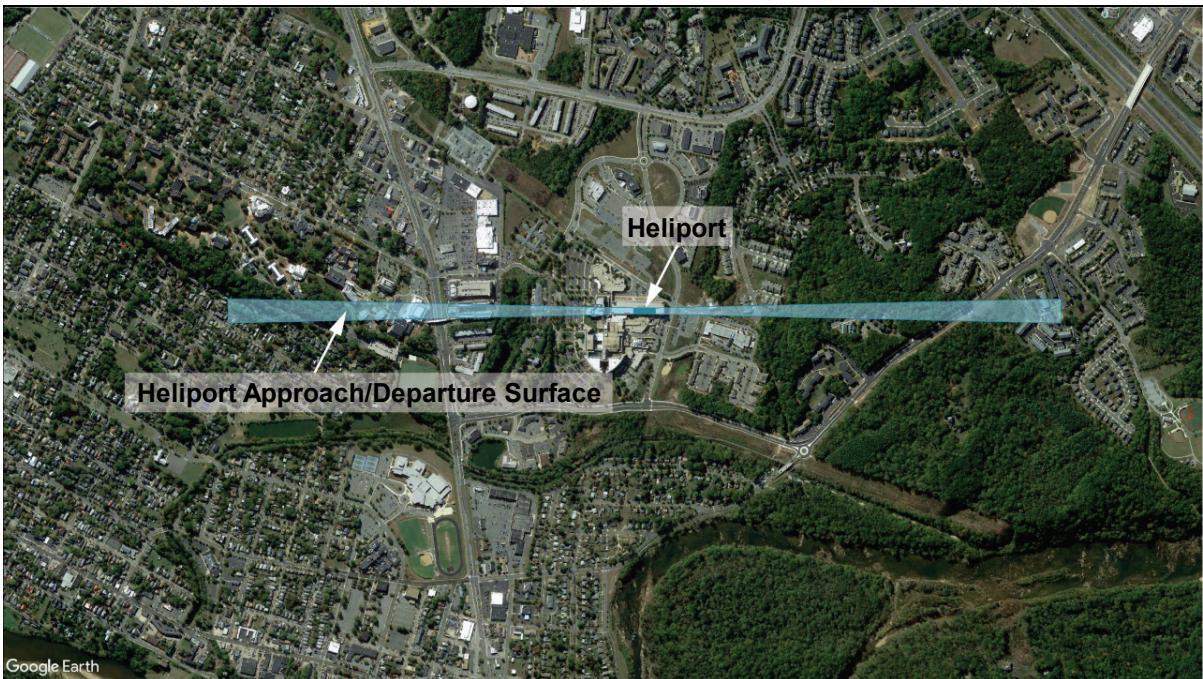
1.10.2 The preferred type of heliport location map using current web-based satellite imagery. Show the location of the heliport site and the approach/departure paths on the map. Point out the heliport site on this map with a red arrow. Indicate the latitude and longitude of the proposed heliport in North American Datum of 1983 (NAD-83) coordinates. See Figure 1-3.
Figure 1-1. FAA Form 7480-1, Notice for Construction, Alteration and Deactivation of Airports
| U.S. Depatment of Transportation OMBCONTROLNUMBER:2120-0036Federal Aviation Administration EXPIRATIONDATE:11/30/2022 |
| NOTICE FOR CONSTRUCTION, ALTERATION AND DEACTIVATION OF AIRPORTS |
| A. Airport Owner Check if this is also the Property Owner | B. Airport Manager (Complete if different than the Airport Owner) |
| 1.Name and Address Check if this is the Airport's Physical Address | 1.Name and Address Check if this is the Airport's Physical Address |
| 2.Phone | 3.Email | 2.Phone | 3.Email |
| C. Purpose of Notification (Answer allquestions that apply) | D. Name, Location, Use and Type of Landing Area |
| 1.Construct orEstablish an: | AiportUtralight Fightpark□BallonportHeliport□Seaplane Base □Other | 1.Name of Landing Area | 2.Loc ID (for existing) |
| 2.Construct, AlterorRealign a | □Runway□Helipad(s) □other□TaxiwayPublic UseAiports only) | 3.Associated City and State | 4.Distance from City(mm) |
| 3.Change StatusFrom/To: | □VFR to IFR □IFR to VFR□Private Use to Public Use□Public Use to Other | 5.County(Physical Location) | 6.Direction from City |
| 4.Change Traff cPattern | □DIRECTION:ALTITUDEChee Litalitueif nortannTurbo:std.nonstd. Prop:□stdnonstd.Helo. std nonstd. Otter Describein boxC6. | 7.Latitude。 1 = | 8. Longitude。 1 " | 9.Elevation |
| 10.CurentUse: | PrivatePublic Private Use of Public Lands |
| 5.Deactivate | Airpot RWY □TWY | 11.Ownership | □PrivatePublic Military(Branch) |
| 6. Description: | 12.Airport □Airport Ultralight Flihtpark BallonportHeliport(applicable elecAmbulanceLaw EnforcementType: Fire Protection) Seaplane Base□Other |
| E. Landing Area Data (List any Proposed, New or Unregistered Runways, Helipads etc.) | | | | | | | |
| 1.Airport, Seaplane Base or Ultralight Flightpark (use second pageif needed) | 2.Heliport, Balloonport or other Landing Area (use second pageif needed) |
| RWY ID | / | / | Helipad ID | | |
| Lat. & Long. | Show on attachment(s) | Showon attachment(s) | Lat. & Long. | Show on atachment(s) | Show on attachment(s) |
| Surface Type | | | Surface Type | | |
| Length feet) | | | TLOF Dimensions | | |
| Width feet) | | | FATO Dimensions | | |
| Lighting (f any) | | | Lighting (if any) | | |
| Right Tratic (YN) | / | / | Ingress/Egress (Degrees) | | |
| Elevation (AMSL) | Show on attachment(s) | Showon attachment(s) | Elevation (AMSL) | Showon attachment(s) | Show on attachment(s) |
| VFR or IFR | / | / | Elevated Height (AGL) | | |
| F.Operational Dat | F. Operational Data (Indicate if the number provided is Actual or Estimated) |
| 1.Number of Based Aircraft | 2.Average Number of Monthly Landings |
| Present or Estim ated | Estimated in 5 Years | Present or Estimated | Estimated in 5 Years |
| Single Engine | | | | |
| Muli Engine | | | | |
| Jet | | | | |
| Helicopter | | | | |
| Glider | | | | |
| Military | | | | |
| Utralight | | | | |
| 3haie |
| 4.Are IFRProcedures forthe Airport Anticipated?□Yes□No.IfYes,within _years |
| G.CERTereycerify hatalof theabvestateertsae earetreancopleteheestofy wee. |
| 1.Name,tite of person fing this notice (ype or prit) | 2.Signature (inink) |
| 3.Date 4.Phone 5.Email |
FAAForm7480-1(7/20)SUPERSEDES PREVIOUSEDITION
See online FAA Form 7480-1.
Figure 1-2. Example of a Heliport Layout Plan
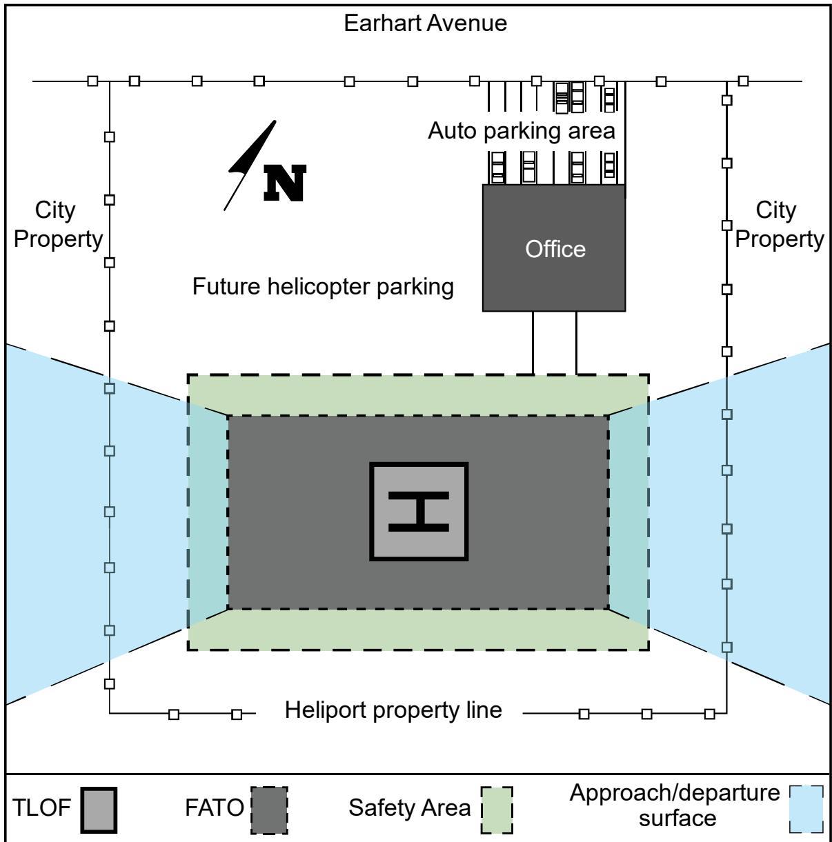
Draw heliport layout plan to scale with key dimensions and locations, including:
a. TLOF and FATO size
b. Safety area dimensions
c. Distances from the safety area perimeter to property boundaries, buildings, etc.
d. Site furnishings (bollards, signs, benches, and other site accessories)
See Chapter 2 for guidance on heliport facility sizes and shapes.
Figure 1-3. Example of a Heliport Location Map
## 1.10.3 The FAA Role.
The FAA will conduct an aeronautical study of the proposed heliport under § 157.7, FAA Determinations. Part (a) of this section of the regulation states:
“The FAA will conduct an aeronautical study of an airport proposal and, after consultations with interested persons, as appropriate, issue a determination to the proponent and advise those concerned of the FAA determination. The FAA will consider matters such as the effects the proposed action would have on existing or contemplated traffic patterns of neighboring airports; the effects the proposed action would have on the existing airspace structure and projected programs of the FAA; and the effects that existing or proposed manmade objects (on file with the FAA) and natural objects within the affected area would have on the airport proposal. While determinations consider the effects of the proposed action on the safe and efficient use of airspace by aircraft and the safety of persons and property on the ground, the determinations are only advisory. Except for an objectionable determination, each determination will contain a determinationvoid date to facilitate efficient planning of the use of the navigable airspace. A determination does not relieve the proponent of responsibility for compliance with any local law, ordinance or regulation, or state or other federal regulation. Aeronautical studies and determinations will not consider environmental or land use compatibility impacts.”
## 1.10.4 Penalty for Failure to Provide Notice.
Persons who fail to give notice are subject to civil penalty under Title 49 United States Code 46301, Civil Penalties, of not more than \$25,000 (or \$1,100 if the person is an individual or small business concern).
## 1.10.5 Notice Exemptions.
Section 157.1, Applicability, exempts sites meeting one of the conditions below from the requirement to submit notice. These exemptions do not negate a notice or formal approval requirement prescribed by state law or local ordinance. For the purposes of applying the Part 157 exemption criteria cited in (2) and (3) below, a landing and associated takeoff is considered one operation. Section 157.1 projects are:
[A heliport] subject to conditions of a federal agreement that requires an approved current heliport layout plan to be on file with the FAA, or
[A heliport] at which flight operations will be conducted under visual flight rules (VFR) and which is used or intended to be used for a period of less than 30 consecutive days with no more than ten operations per day.
The intermittent use of a site that is not an established airport, that is used or intended to be used for less than one year, and at which flight operations will be conducted only under VFR. For this part, “intermittent use of a site” means:
a. the site is used or is intended to be used for no more than three days in any one week, and
b. no more than ten operations will be conducted in any one day at that site.
## 1.11 Hazards to Air Navigation.
Part 77 establishes requirements for notification to the FAA of objects that may affect navigable airspace. See Figure 1-4 for examples of development requiring notice to the FAA.
Part 77 sets standards for determining obstructions to navigable airspace and provides for aeronautical studies of such obstructions to determine their effect on the safe and efficient use of airspace. Part 77 applies only to the following:
public heliports and public airports;
airports operated by a federal agency or the Department of Defense (DoD); and
private airports and heliports with at least one FAA-approved instrument approach procedure.
## 1.11.1 FAA Studies.
## 1.11.1.1 Part 77.
Part 77 defines objects that are obstructions to surfaces. Presume these objects to be hazards to air navigation unless an FAA study determines otherwise. The FAA conducts aeronautical studies to determine the
physical and electromagnetic effect on the use of navigable airspace, air navigational facilities, public airports and heliports, and private airports and heliports with at least one FAA-approved instrument approach procedure. The FAA encourages public agencies to enact zoning ordinances to prevent man-made features from becoming hazards to navigation.
## 1.11.1.2 Part 157.
FAA aeronautical studies performed under Part 157 establish standards and notification requirements for anyone proposing to construct, alter, or deactivate a civil or joint-use (civil/military) airport or heliport. This regulation also addresses proposals that alter the status or use of airport or heliport facilities.
## 1.11.2 Mitigation of Hazards.
You may mitigate the adverse effect of an object presumed or determined to be a hazard by:
Removing the object.
Altering the object, for example, reducing its height.
Marking and/or lighting the object, provided an FAA aeronautical study has determined that the object would not be a hazard to air navigation if it were marked and/or lighted. Find guidance on marking and lighting objects in AC 70/7460-1, Obstruction Marking and Lighting.
## 1.11.3 Notification Requirements.
Part 77 requires persons proposing certain construction or alteration to give a 45-day notice to the FAA of their intent. Use FAA Form 7460-1, Notice of Proposed Construction or Alteration, to provide notification. See https://oeaaa.faa.gov/ for more information and to download FAA Form 7460-1. Alterations to an existing heliport requiring notification could include changes to heliport dimensions, approach and departure surfaces, heliport location, and heliport relocation to a different site.
Figure 1-4. Offsite Development Requiring Notice to the FAA
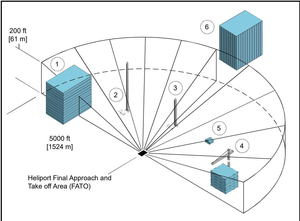
Notice under Part 77 is required for all public-use heliports or private-use heliports with at least one FAA-approved instrument approach procedure.
## Offsite Development Examples for Figure 1-4:
① Building is less than 200 feet (ft) (61 meters (m)) in height, but top will penetrate the 25:1 surface (notice required by § 77.9).
② Antenna is over 200 ft (61 m) in height (notice is required by § 77.9(a)).
③ Antenna is less than 200 ft (61 m) in height and penetrates the 25:1 surface (notice is required by § 77.9(b)(3)).
④ Construction crane penetrates 25:1 surface (notice is required by § 77.9(b)(3)).
⑤ Building is less than 200 ft (61 m) in height and does not penetrate the 25:1 surface (notice is not required).
⑥ Building is more than 5,000 ft (1,524 m) from heliport (notice is required if building will be 200 ft (61 m) or more in height).
## 1.11.4 Heliport Development Plans.
Future public heliport development plans and feasibility studies on file with the FAA may influence the determinations resulting from Part 77 studies. Owners of public and private heliports with FAA-approved instrument approach procedures can ensure full consideration of future heliport development in Part 77 studies only when they file plans with the FAA. Ensure the coordinates and elevations of planned FATO(s),
approach/departure paths including their azimuths, and types of approaches for any new FATO or modification of an existing FATO are included in heliport plan data.
## 1.12 Federal Assistance.
The FAA administers a grant program that provides financial assistance to eligible sponsors to develop a public-use heliport. Information on federal aid program eligibility requirements is available from FAA Airports Regional and District Offices and on the FAA Airports website, www.faa.gov/airports.
## 1.13 Environmental Impact Analyses.
The National Environmental Policy Act (NEPA) of 1969 requires the FAA to consider potential environmental impacts prior to agency decision making, including, for example, the decision to fund or approve a project, plan, license, permit, certification, rulemaking, or operations specification. Actions that may warrant an environmental review are normally associated with federal grants or airport layout plan (ALP) approvals leading to the construction of a new heliport or significant expansion of an existing heliport.
## 1.13.1 Environmental Review Items.
An environmental review addresses noise, historic and cultural resources, wildlife, energy conservation, land usage, air quality, water quality, pollution prevention, light emissions, and other visual effects, and other public health and safety issues. The review evaluates the “no action” alternative and a reasonable range of feasible alternatives, including mitigation not included in the initial alternative. The review will also describe actions taken to ensure public involvement in the planning process. An opportunity for a public hearing may be required for the federally funded development of, or significant improvement to, an existing heliport.
## 1.13.2 Guidance.
FAA Order 1050.1, Polices and Procedures for Considering Environmental Impacts, FAA Order 5050.4, National Environmental Policy Act (NEPA) Implementing Instructions for Airport Projects, and other supplemental guidance from FAA Air Traffic and Flight Standards provide guidance on environmental impact analysis. Contact state and local governments, including metropolitan planning organizations and local transit agencies, directly, as they may also necessitate an environmental report. The procedures in AC 150/5020-1, Noise Control and Compatibility Planning for Airports, describe a means of assessing the noise impact. Contact the appropriate FAA Airports Regional or District Office for current information related to assessing the noise impact of heliports. Proponents of non-federally assisted heliports work with local governmental authorities concerning environmental issues.
## 1.14 Terminal Facilities Design Considerations.
A heliport terminal provides curbside access for passengers using private autos, taxicabs, and public transit vehicles. Public waiting areas need the usual amenities, and a counter for rental car services may be desirable. Design passenger auto parking areas to accommodate current requirements, with the ability to expand them to meet future requirements. Readily available public transportation may reduce the requirement for employee and service personnel auto parking spaces. Build attractive and functional heliport terminal buildings or sheltered waiting areas. Guidance on designing terminal facilities is provided in AC 150/5360-13, Airport Terminal Planning.
At PPR heliports, the number of people using the facility may be so small that there is no need for a terminal building, and minimal needs for other facilities and amenities.
## 1.14.1 Security – TRANSPORT Heliports.
Unless screening was carried out at the helicopter passengers’ departure location, Transportation Security Administration regulations may require that a screening area and/or screening be provided before passengers enter the airport’s secured areas. If needed, provide multiple helicopter parking positions and/or locations in the terminal area to service helicopter passenger and/or cargo interconnecting needs. Find information about passenger screening at the Transportation Security Administration website (https://www.tsa.gov/public/).
## 1.15 Zoning for Compatible Land Use.
The FAA encourages all heliport operators to promote the adoption of the following zoning measures where state and local statutes permit to ensure the heliport will continue to be available and to protect the investment in the facility.
## 1.15.1 Zoning to Limit Building/Object Heights.
Find general guidance on drafting an ordinance that would limit building and object heights in AC 150/5190-4, A Model Zoning Ordinance to Limit Height of Objects Around Airports. Substitute the heliport surfaces for the airport surfaces described in the model ordinance.
## 1.15.2 Zoning for Compatible Land Use.
The FAA encourages public agencies to enact zoning ordinances to control the use of property within the HPZ and the approach/departure path environment, restricting activities to those that are compatible with helicopter operations. See paragraph 2.13.
## 1.15.3 Air Rights and Property Easements.
Use air rights and property easements as options to prevent the encroachment of obstacles near a heliport.
## 1.16 Access to Heliports by Individuals with Disabilities.
Congress has passed various laws concerning access to airports. Since heliports are a type of airport, these laws are similarly applicable. Find guidance in AC 150/5360-14, Access to Airports by Individuals with Disabilities.
## 1.17 State Role.
Many state departments of transportation, aeronautical commissions, or similar authorities require prior approval and, in some instances, a license for the establishment and operation of a heliport. Several states administer a financial assistance program like the federal program and are staffed to provide technical advice. Contact your respective state aeronautics commissions or departments for specifics on licensing and assistance programs. Contact information for state aviation agencies is available at https://www.faa.gov/airports/resources/state\_aviation.
## 1.18 Local Role and Building Code.
Some communities have enacted zoning laws, building codes, fire regulations, etc., that can affect heliport establishment and operation. Most municipalities have a formal process such as a “Conditional Use Permit” in place for the establishment of a heliport. Check with your local Planning and Zoning Commission for details. Some have or are in the process of developing codes or ordinances regulating environmental issues such as noise and air pollution. A few localities have enacted specific rules governing the establishment of a heliport. Therefore, make early contact with officials or agencies representing the local zoning board, the fire, police, or sheriff's department, and elected personnel who represent the area where the heliport is to be located.
## 1.19 Related Referenced Material.
Find a list of associated publications and references in Appendix E.
# CHAPTER 2. Heliport Design
## 2.1 General.
This chapter provides guidance on the design of heliports. There are three types of heliports. GENERAL AVIATION, TRANSPORT, and HOSPITAL. Figure 2-1, Figure 2-2, and Figure 2-3 show basic features of these three heliport types. See paragraph 1.8 for descriptions of the three heliport types. This chapter provides general heliport design guidance and also highlights any differences in design elements among the types of heliports.
## 2.2 Prior Permission Required (PPR) Facilities.
Unless required by federal law or regulation, the recommendations in this AC are not mandatory for PPR heliports. Recommendations for PPR heliports are provided due to the specific nature of these heliport facilities where the operator ensures that pilots are thoroughly familiar with the heliport, its procedures, and any facility limitations.
## 2.3 Design Approach.
The design standards in this chapter assume that there will never be more than one helicopter within the FATO and the associated safety area. A TLOF can be located within the FATO or outside the FATO, as described in paragraph 2.7.
## 2.4 Access by Individuals with Disabilities.
Various laws require heliports operated by public entities and those receiving federal financial assistance to meet accessibility requirements. See paragraph 1.16.
Figure 2-1. GENERAL AVIATION Heliport – Basic Features
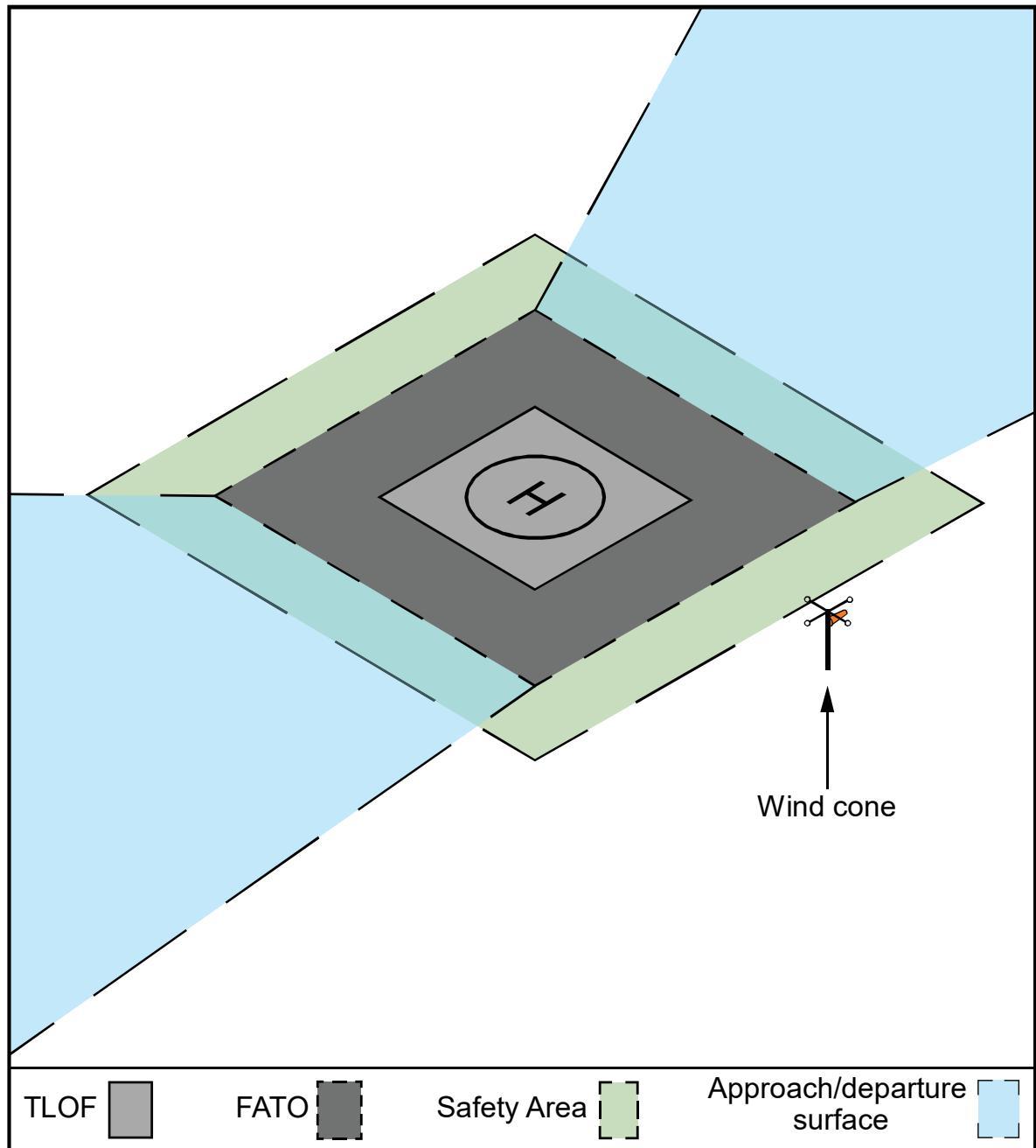
See Chapter 4 for guidance on heliport markings.
Locate the wind cone outside of the Safety Area. Ensure the wind cone and any security fencing or security barrier will not interfere with the approach/departure surface or transitional surface.
Figure 2-2. TRANSPORT Heliport – Basic Features
See Chapter 4 for guidance on heliport markings.
Locate the wind cone outside of the Safety Area. Ensure that the wind cone and any security fencing or security barrier will not interfere with the approach/departure surface or transitional surface.
Figure 2-3. HOSPITAL Heliport (Ground Level) – Basic Features
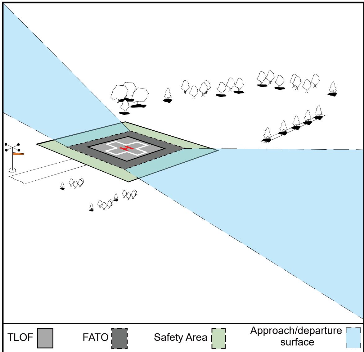
Locate the security fence and wind cone outside of the Safety Area. Ensure that the wind cone and any security fencing or security barrier will not interfere with the approach/departure surface or transitional surface.
See Chapter 4 for guidance on heliport markings.
## 2.5 Heliport Site Selection.
## 2.5.1 Long-term Planning.
The FAA encourages public agencies and others planning to develop a GENERAL AVIATION, TRANSPORT, or HOSPITAL heliport to consider the possible future need for instrument operations and facility expansion. Consider any current or future potential use by military helicopters that may be used in disaster relief efforts during planning for HOSPITAL heliports.
## 2.5.2 Property Requirements.
The property needed for GENERAL AVIATION and TRANSPORT heliports is dependent upon the volume and types of users, helicopter sizes, and the scope of amenities provided for each type of heliport facility. Property requirements for helicopter operators and for passenger amenities frequently exceed the property needed for “airside” purposes. The area needed for heliport or helipad operations may be as simple as a cleared area on the ground, a wind cone, and a clear approach/departure path for day heliport operations.
## 2.5.3 Turbulence.
Air flowing around and over buildings, stands of trees, terrain irregularities, etc., can create turbulence on ground-level and roof-top heliports that may affect helicopter operations. Assess the turbulence and airflow characteristics near, and across the surface of the FATO, and along the final section of the approach/departure path to determine if an air gap among the roof, roof parapet or supporting structure, and/or some other turbulence mitigating design measure is necessary. Perform this assessment where the FATO is located near the edge and top of a building or structure, or within the influence of turbulent wakes from other buildings or structures. The FAA’s Technical Report FAA/RD-84/25, Evaluating Wind Flow around Buildings on Heliport Placement, addresses the wind’s effect on helicopter operations. Take the following actions in selecting a site to minimize the effects of turbulence, as described in paragraphs below.
## 2.5.3.1 Ground-Level Heliports.
Proximity of buildings, trees, and other large objects to ground-level heliports can cause air turbulence and affect helicopter operations. Locate the landing and takeoff area away from such objects to minimize air turbulence near the FATO and the approach/departure paths.
## 2.5.3.2 Elevated Heliports.
Establishing a 6-foot (1.8 m) or more air gap on all sides above the roof level will generally minimize the turbulent effect of air flowing over the roof edge. If an air gap is included in the elevated heliport design, keep it free of objects that would obstruct the airflow. Where it is impractical to include an air gap or other turbulence mitigating design measures, operational limitations may be necessary under certain wind conditions.
## 2.5.4 Electromagnetic Effects.
Nearby electromagnetic devices, such as a large ventilator motor, elevator motor, magnetic resonance imaging machine (MRI), or other devices that consume large amounts of electricity may cause temporary abnormalities in the helicopter magnetic compass and interfere with other onboard navigational equipment. Buried rebar or other objects made of iron/steel below the heliport surface have also been shown to interfere with a helicopter’s navigation instruments.
Be alert to the location of any such devices with respect to a HOSPITAL heliport. A warning sign alerting pilots to the presence of an MRI is recommended. Take steps to inform pilots of the MRI locations or other electromagnetic equipment that consume large amounts of electricity. Heliports are recommended to include Heliport electromagnetic interference (EMI) hazard marking and signage to alert pilots to potential EMI impacts, as shown in Figure 2-4 and Figure 2-5. Locate the EMI hazard sign at ingress/egress points on the heliport for maximum visibility.
For additional information, see the FAA’s Technical Report FAA/RD-92/15, Potential Hazards of Magnetic Resonance Imagers to Emergency Medical Service Helicopter Services.
Figure 2-4. Heliport EMI Hazard Marking

Align the compass with magnetic north. Use arrows, as shown, to indicate the four cardinal headings (N, S, E, W) and four intercardinal headings (NE, SE, SW, and NW).
Use a minimum dimension of a 6-foot (1.8 m) outer diameter and a 4-foot (1.2 m) inner diameter for the compass circle.
Use blue paint for the compass circle and white paint for the inner portion of the compass. If necessary for visual contrast, use a one-foot white outline along the outer edge of the compass and arrows.
Figure 2-5. Heliport EMI Hazard Sign
# CAUTION

Strong Magnetic Field
Aircraft navigational instruments may be affected. Confirm accuracy of navigation instruments during all operations.
## 2.6 TLOF/FATO and Safety Area Relationships.
The relationship, minimum dimensions, and separation distances of the TLOF, FATO and safety area are shown in Figure 2-6 and Table 2-1. A heliport consists of the following:
A TLOF is typically located within a FATO but can be located outside of the FATO. See paragraph 2.7.1.
A safety area which surrounds the FATO.
Approach/departure surfaces to allow safe approaches to and departures from a heliport landing sites.
Figure 2-6. TLOF/FATO/Safety Area Relationships and Minimum Dimensions
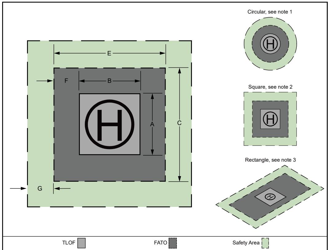
For a circular TLOF and FATO, dimensions A, B, C, and E refer to diameters.
For a square TLOF and FATO, all sides of the TLOF and FATO have equal length (e.g., dimension E = dimension C and dimension A = dimension B).
For a square TLOF with a rectangular FATO, dimension E ≠ dimension C.
Table 2-1. TLOF/FATO Minimum Dimensions 1
| TRANSPORT FATO | GA/HOSPITALLoad-bearing FATO |
| Lights | Use green lights meeting therequirements of Appendix Gto define the limits of theFATO. | • Use green lights meeting the requirements ofAppendix G to define the perimeter of a load-bearing FATO. Do not light the FATO perimeter if anyportion of the FATO is not a load-bearingsurface. |
| Locationand spacing | • See Figure 4-11 for lightspacing and layout. | Install a minimum of four (minimum of threelights for PPR and HOSPITAL heliports) in- pavement per side of a square or rectangularFATO.• Space lighting 25 ft (7.6 m) maximumspacing. |
| Installationguidance | • Mount frangible elevatedlight fixtures 10 feet (3 m) outfrom the FATO perimeter.• Ensure they do not penetrate ahorizontal plane at theadjacent TLOF elevation bymore than 2 inches (51 mm). | • N/A |
| ElevatedFATO | Lighting for an elevatedFATO is the same as for aground-level FATO.Ensure the elevated lights donot penetrate a horizontalplane at the adjacent TLOF | • In the case of an elevated FATO with a safetynet, mount the perimeter lights, as described in paragraph 4.13.2.• As an option, locate elevated FATO perimeterlights, no more than 2 inches (51 mm) high, |
| elevation by more than 2 inches (51 mm). | 10 feet (3 m) from the FATO perimeter. See Figure 4-11. Ensure the elevated lights do not penetrate a horizontal plane at the adjacent TLOF elevation by more than 2 inches (51 mm). |
| Circular FATO | • N/A | To define a circular FATO, use an even number of lights, with a minimum of eight light fixtures uniformly spaced. Locate in-pavement lights within 1 foot (0.3 m) inside or outside of the FATO perimeter See Figure 4-10. As an option, use a square or rectangular pattern of FATO perimeter lights even if the TLOF is circular. At a distance during nighttime operations, a square or rectangular pattern of FATO perimeter lights may provide the pilot with better visual alignment cues than a circular pattern, but a circular pattern may be more effective in an urban environment. |
Figure 4-12. FATO Elevation
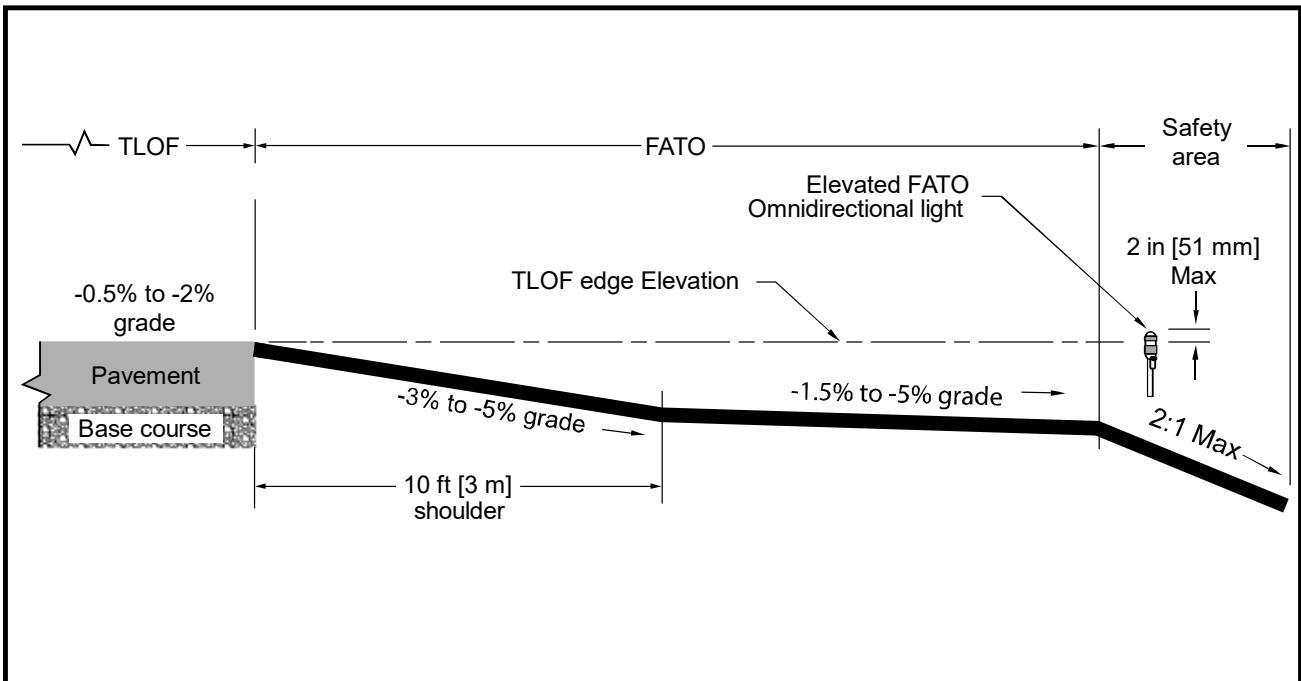
See paragraph 4.13.3 for guidance on FATO lights.
## 4.13.4 Floodlights.
The FAA has not evaluated floodlights for effectiveness in visual acquisition of a heliport. Guidelines for the use and installation of floodlights includes:
TRANSPORT Heliports – Install floodlights to illuminate the helicopter parking areas.
GENERAL AVIATION and HOSPITAL Heliports – Install floodlights to illuminate the TLOF, the FATO, and/or the parking area if ambient light does not suitably illuminate markings for night operations.
Mount these floodlights on adjacent buildings to eliminate the need for tall poles, if possible. Place floodlights clear of the TLOF, the FATO, the safety area, the approach/departure surfaces, and transitional surfaces and ensure floodlights and their associated hardware do not constitute an obstruction hazard.
Aim floodlights down to provide adequate illumination on the apron and parking surface.
Ensure floodlights that might interfere with pilot vision during takeoff and landings are capable of being turned off by pilot control or at pilot request.
Note 1: Floodlights do not replace TLOF or FATO lighting recommendations.
Note 2: White lighting for heliport applications should not be activated until the aircraft has landed and deactivated prior to takeoff.
## 4.13.5 Landing Direction Lights.
Install landing direction lights when it is necessary to provide directional guidance to indicate available approach and/or departure path directions as an option, as follows:
Landing direction lights are a configuration of five green, omnidirectional lights meeting the standards of Appendix G, located on the centerline of the preferred approach/departure paths.
Space these lights at 15-foot (4.6 m) intervals extending outward in the direction of the preferred approach/departure paths, with spacing and layout, as illustrated in Figure 4-13.
Figure 4-13. Landing Direction Lights.
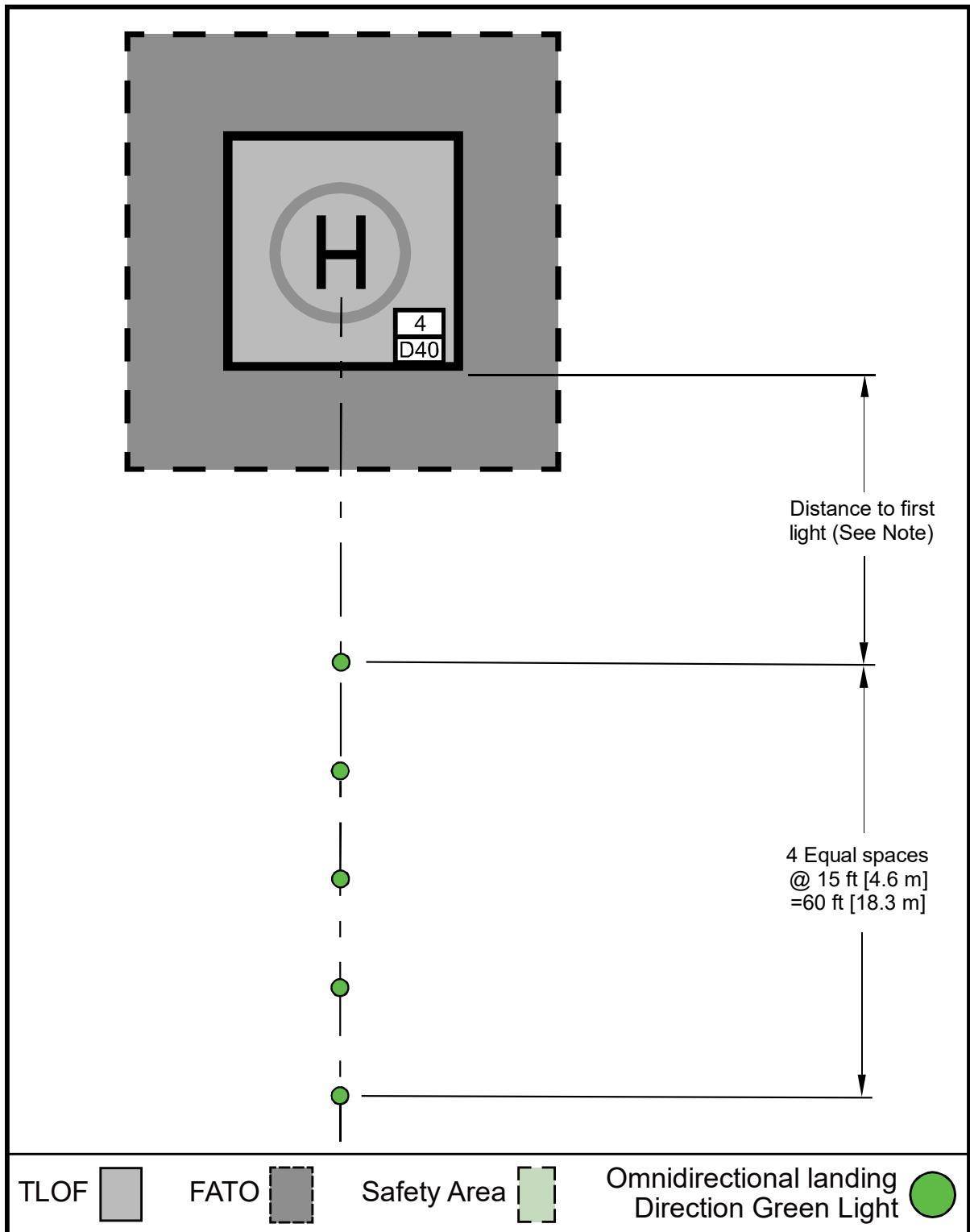
Locate the first omnidirectional landing direction light 20-60 ft (6.1-18.3 m) from the TLOF for GENERAL AVIATION and HOSPITAL heliports, and 30-60 ft (9.1-18.3 m) from the TLOF for TRANSPORT heliports.
See paragraph 4.13.5 for guidance on landing direction lights.
## 4.13.6 Flight Path Alignment Lights.
Flight path alignment lights provide approach and/or departure path directions in a straight line along the direction of approach and/or departure flight paths. If necessary, they may extend across the TLOF, FATO, safety area, or any suitable surface in the immediate vicinity of the FATO or safety area. Use three or more green lights spaced at 5 ft (1.5 m) to 10 ft (3 m).
Install flight path alignment lights meeting the requirements of Appendix G as an option.
Place these lights in a straight line along the direction of approach and/or departure flight paths.
Extend the lights across the TLOF, FATO, safety area, or any suitable surface in the immediate vicinity of the FATO or safety area, if necessary.
Install three or more green lights spaced at 5 feet (1.5 m) to 10 feet (3 m). See Figure 2-19.
## 4.13.7 Taxiway and Taxi Route Lighting.
## 4.13.7.1 Optional Taxiway and Taxi Route Lighting.
Install taxiway centerline lights per the following guidelines:
Install in-pavement bidirectional green taxiway centerline lights meeting the standards of AC 150/5345-46, Specification for Runway and Taxiway Light Fixtures, for type L-852A (straight segments) or L-852B (curved segments).
Space these lights at maximum 50-foot (15.2 m) longitudinal intervals on straight segments and at maximum 25-foot (7.6 m) intervals on curved segments, using a minimum of four lights to define the curve.
Uniformly offset the taxiway centerline lights no more than two feet (0.6 m) to facilitate painting of the taxiway centerline.
For GENERAL AVIATION and HOSPITAL Heliports, green retroreflective markers can be used as an option in lieu of the L-852A or L-852B lighting fixtures.
Use Type I retroreflective markers, as described in AC 150/5345-39, Specification for L-853, Runway and Taxiway Retroreflective Markers.
Do not use retroreflective markers for TRANSPORT heliports.
## 4.13.7.2 Optional Taxiway Edge Lights.
Specify taxiway edge lights per the following guidelines:
For paved taxiways, use type L-852T in-pavement omnidirectional blue lights meeting the standards of AC 150/5345-46 to mark the edges of a taxiway.
Use type L-861T elevated lights meeting the standards of AC 150/5345-46. The lateral spacing for the lights or reflectors is equal to 0.83 D of the design helicopter, but not more than 35 feet (10.7 m).
For unpaved taxiways at GENERAL AVIATION and HOSPITAL heliports, blue retroreflective markers may be used in lieu of lights.
Ensure retroreflective markers are no more than 8 inches (203 mm) tall.
TRANSPORT heliports cannot use retroreflective markers.
Install taxiway edge lights per AC 150/5340-30.
For straight segments, space taxiway edge lights at 50-foot (15.2 m) longitudinal intervals on straight segments.
Curved taxiway segments require smaller spacing of edge lights. The light spacing is based on the radius of the curve, as described in AC 150/5340-30. Space taxiway edge lights uniformly. On curved edges of more than 30 degrees from point of tangency (PT) of the taxiway section to PT of the intersecting surface, install at least three edge lights. For radii not listed in AC 150/5340-30, determine spacing by linear interpolation.
## 4.13.8 Heliport Identification Beacon.
A heliport identification beacon may be used to provide the pilot with a means of visually locating the heliport. The identification beacon is a flashing white/green/yellow with a rate of 30 to 45 flashes per minute. Install beacons per the guidance below:
Install heliport identification beacons for TRANSPORT heliports.
These beacons are optional for GENERAL AVIATION and HOSPITAL heliports. Beacons at these heliports can be pilot controlled (as an option) such that the beacon is “on” only when needed.
Specify a beacon meeting the guidelines provided by AC 150/5345-12, Specification for Airport and Heliport Beacon.
Locate and install the beacon per AC 150/5340-30.
# Page Intentionally Blank
# CHAPTER 5. Helicopter Facilities on Airports
## 5.1 General.
5.1.1 This chapter addresses design considerations for separate helicopter facilities on airports. Helicopters can operate on airports without interfering with airplane traffic. Operations can occur on existing airport infrastructure (e.g., on airport taxiways) or on dedicated heliport facilities, as shown in Figure 5-1. Separate heliport facilities and approach/departure procedures may be needed when the volume of airplane and/or helicopter traffic affects operations.
5.1.2 At airports with interconnecting passenger traffic between helicopters and airlines, provide gates at the terminal for helicopter boarding. People who use a helicopter to go to an airport generally need convenient access to the airport terminal and the services provided to airplane passengers.
5.1.3 Identify the location of the exclusive-use helicopter facilities, TLOFs, FATOs, safety areas, approach/departure paths, and helicopter taxi routes and taxiways on the ALP. Figure 5-1 shows an example of dedicated heliport facilities located on an airport. Other potential heliport locations are on the roofs of passenger terminals or parking garages serving passenger terminals.
## 5.2 Touchdown and Liftoff Area (TLOF).
Locate the TLOF to provide ready access to the airport terminal or to the helicopter user’s origin or destination. Locate the TLOF away from aircraft movement areas (runways, taxiways, and aircraft parking aprons).
## 5.3 On-Airport Location of Final Approach and Takeoff Area (FATO).
See Table 5-1 for standards of the distance between the centerline of an approach to a runway and the centerline of an approach to a FATO for simultaneous, same direction, VFR operations.
Figure 5-1. Example of Heliport Facilities Located on an Airport
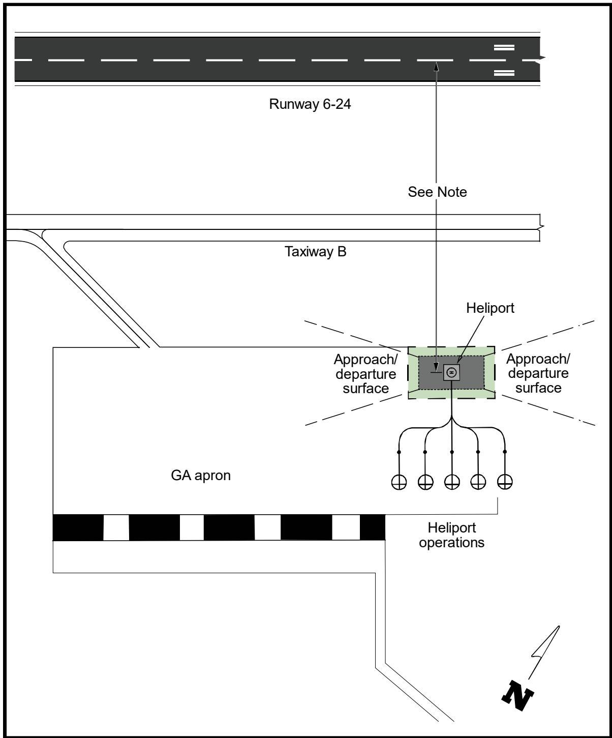
See Table 5-1.
Table 5-1. Recommended Distance between FATO Center to Runway Centerline for VFR Operations
| AAM | advanced air mobility |
| AC | Advisory Circular |
| AC | alternating current |
| AGL | above ground level |
| ALP | Airport Layout Plan |
| AWOS | automated weather observing system |
| CCS | combined charging standard |
| CFR | Code of Federal Regulations |
| D | controlling dimension |
| DC | direct current |
| EB | Engineering Brief |
| ESS | energy storage system |
| ETL | effective translational lift |
| EV | electric vehicle |
| eVTOL | electric vertical takeoff and landing |
| FAA | Federal Aviation Administration |
| FATO | final approach and takeoff area |
| FC | failure condition |
| GA | general aviation |
| HOGE | hover out of ground effect |
| IEC | International Electrotechnical Commission |
| IEEE | Institute of Electrical and Electronics Engineers |
| IFC | International Fire Code |
| IFR | instrument flight rules |
| ISO | International Organization for Standardization |
| LAP | Landing Area Proposal |
| LDR | landing distance required |
| LED | light emitting diode |
| LOB | line of business |
| MCS | megawatt charging system |
| MSL | mean sea level |
| MTOW | maximum takeoff weight |
| NEC | National Electric Code |
| NEPA | National Environmental Policy Act |
| NEMSPA | National EMS Pilots Association |
| NFPA | National Fire Protection Association |
| OEM | original equipment manufacturer |
| OFA | object free area |
| RTODR | rejected takeoff distance required |
| SAE | SAE International |
| TDP | takeoff decision point |
| TLOF | touchdown and liftoff area |
| TODR | takeoff distance required |
| TSA | Transportation Security Administration |
| UL | Underwriters Laboratories |
| VFR | visual flight rule |
| VGSI | Visual Glideslope Indicator |
| VMC | visual meteorological conditions |
| VTOL | vertical takeoff and landing |
# CASA Vertiport设计指南
# CASA AC139.V-01 Guidance on Vertiport Design (2023)
## ADVISORY CIRCULAR AC 139.V-01v1.0
Guidance for vertiport design
Advisory circulars are intended to provide advice and guidance to illustrate a means, but not necessarily the only means, of complying with the Regulations, or to explain certain regulatory requirements by providing informative, interpretative and explanatory material.
Advisory circulars should always be read in conjunction with the relevant regulations.
## Audience
This advisory circular (AC) applies to:
persons involved in the design, construction, and operation of vertiports
proponents of vertiports
AAM aircraft owners/operators
planning authorities
aerodrome operators
the Civil Aviation Safety Authority (CASA).
## Purpose
This AC provides initial guidance in the planning and physical design of vertiports to support the safe and efficient operation of vertical take-off and landing (VTOL) capable aircraft operating with a pilot on board in visual conditions only.
This AC is not intended to restrict or limit a pilot from determining the most suitable area for landing or take-off for the VTOL-capable aircraft operation.
Where possible, outcome-based guidance is provided. While regulations were previously written in a prescriptive manner , organisations are now also required to develop processes that will deliver an effective outcome.
For more information on understanding outcome-based legislation see AC 1-01 - Understanding the legislative framework.
## For further information
For further information, contact CASA’s Personnel Licensing, Aerodromes and Air Navigation Standards (telephone 131 757).
Unless specified otherwise, all subregulations, regulations, Divisions, Subparts and Parts referenced in this AC are references to the Civil Aviation Safety Regulations 1998 (CASR).
## Status
This version of the AC is approved by the Branch Manager, Flight Standards.
| Term | Definition |
| Aerodrome | An area on land or water (including any buildings, installations, and equipment), the use of which as an aerodrome is authorised under the regulations, being such an area intended to be used either wholly or in part for the arrival, departure, and movement of aircraft. |
| Barrette | means 3 or more lights closely spaced in a transverse line so that from a distance they appear as a short bar of light. |
| D | for VTOL-capable aircraft, means the diameter of the smallest circle enclosing the aircraft projected on a horizontal plane, while the aircraft is in the take-off or landing configuration, with lift/thrust units turning, if applicable. |
| Note: If the aircraft changes dimensions during taxing or parking (e.g. folding wings), a corresponding Dtaxing or Dparking should also be provided. |
| Design D Design aircraft | the D of the design aircraft. means a virtual aircraft type that has the largest set of dimensions, the |
| greatest maximum take-off weight (MTOW), and the most critical obstacle avoidance criteria of the aircraft that the vertiport, or for a defined area within the vertiport, is intended to serve. |
| Downwash protection zone | The downwash protection zone is designed to protect the general public, other aircraft and those working in the immediate vicinity of operating VCA from the effect of buffeting. |
| D-Value | A limiting dimension, in terms of D, for a vertiport, or for a defined area within the vertiport. |
| Elevated vertiport | is a vertiport with a FATO location that would introduce a risk of fall from height or introduces a hazard to aircraft operations or to other people within the structure under the vertiport. |
| Elongated | when used with TLOF or FATO, elongated means an area which has a length more than twice its width. |
| Essential objects permitted | includes, but may not be limited to, around the touchdown and lift-off area (TLOF), perimeter lights and floodlights, guttering and raised kerb, foam monitors or ring-main system, handrails and associated signage, other lights. |
| off area (FATO) a. | Final approach and take- For the operation of a VTOL-capable aircraft, is defined as a solid area: from which a take-off is commenced; |
| Lighting element | or b. over which the final phase of approach to hover is completed. A lighting element is a light source within a lighting segment that may be |
| discrete (e.g., a Light Emitting Diode (LED)) or continuous (e.g., fibre optic cable, electro luminescent panel). An individual lighting element may consist of a single light source or multiple light sources arranged in a group or cluster and may include a lens/diffuser. |
| Lighting segments | Lighting segments are low profile lighting fixtures that consists of a line of lighting elements within unit or frame. For the purposes of this circular, the dimensions of a lighting segment are the |
| (LPs) are examples of lighting segments. |
| Obstacle | An object (whether temporary or permanent) or part of such an object that: |
| a. is located on an area provided for the movement of aircraft; or |
| b. extends above a defined surface designated to protect aircraft in flight |
| Obstacle free volume (OFV) | is a defined volume of airspace between the FATO protection area and the VPS, designed to protect aircraft conducting vertical procedures. |
| Protection area | means a defined area on a vertiport, which surrounds either the FATO or a stand, intended to reduce the risk of damage to an aircraft diverging from the |
| Reference circle | FATO or stand. is a horizontal circle, of the specified dimension, that is centred on any intended position/flight path at or above the applicable area/surface. |
| Rejected take-off distance required (RTODRV) | means the horizontal distance that is required from the start of the take-off to the point where the aircraft comes to a full stop, following a critical failure that is recognised at the TDP. |
| Take-off decision point (TDP) | means the first point that is defined by a combination of speed and height from which a safe take-off can be continued following a critical failure and is the last point in the take-off path from which a rejected take-off is ensured. |
| Touchdown and lift-off area (TLOF) | an area where a VTOL-capable aircraft may touch down or lift off. |
| Touchdown/positioning circle (TDPC) | a TDPM in the form of a circle, which is used for omnidirectional positioning in a TLOF. |
| Touchdown/positioning marking (TDPM) | a marking or set of markings that provide visual cues for the positioning of an aircraft. |
| Vertical procedures | take-of and landing procedures that include an initial and/or final vertical profile. The profile may or may not include a horizontal component. |
| Vertical procedure surface (VPS) | a surface at which a VTOL-capable aircraft either: a. begins its arriving vertical procedure, |
| or b. ends its departing vertical procedure. |
| Vertiport elevation | the highest point of the FATO, or where there are multiple FATOs, the highest point of the highest FATO. |
| Vertiport | an area of land, water, or structure that is used or intended to be used for the landing, take-off, and movement of VTOL-capable aircraft, that meets or exceeds the specifications contained within this advisory circular. |
| For the purposes of this AC the term vertiport also includes vertihubs and |
| vertistops: a. | Vertihub: a vertiport with infrastructure for maintenance, repair, fuelling, and parking spaces for storage of VTOL-capable aircraft. |
| b. Vertistop: a vertiport intended for take-off and landing of VTOL- capable aircraft to drop off or pick up passenger or cargo, but where |
| Vertiport clearway | means a defined horizontal surface selected and/or prepared as a suitable area over which an aircraft, capable of continued safe flight after a critical failure, may operate between the FATO/VPS and the approach/climb-out surface inner edge. |
| VCA (VTOL-capable aircraft) | a heavier-than-air aircraft, other than aeroplane or helicopter, capable of performing vertical procedures by means of more than two lift/thrust units. |
| VCA stand | a defined area that is intended to accommodate aircraft for loading or unloading passengers, mail, or cargo, fuelling/charging, parking, or |
| VCA taxi-route | maintenance. a defined path that is established for the movement of aircraft from one part of a vertiport to another: |
| a. an air taxi-route: a marked taxi-route that is intended for air taxing; and |
| b. a ground taxi-route: a taxi-route that is intended for ground movement of aircraft centred on a VCA taxiway. |
## 1.3 References
## Advisory material
CASA's advisory materials are available at https://www.casa.gov.au/publications-and-resources/guidance-materials
| Use of light | Description | Example | |
| Flight path alignment guidance lighting system (FPAGLS) | The FPAGLS provides an indication of available landing and take-off path directions. These are the lights that match with the alignment guidance markings and should be located within the marking as far as practicable. With the recommended minimum |  |
| distance between the first and last of the lights being 6 m, there will be instances where |
| FATO perimeter lights |
| Aiming point lights | pilots with a visual means to acquire the FATO while on approach to the vertiport. This system is a series of six white lights located within the white line of the triangular aiming point marking, one light |
| located at each point and one light located between each pair of corner lights. TLOF lighting systems | There are a few options for TLOF lighting systems. The options are dependent on the locations of the TLOF. TLOFs within a FATO should by lit by green perimeter lights or yellow TDPC lighting segments, while TLOFs within a parking stand are |
| TLOF perimeter lighting | lit by flodlighting. Green TLOF perimeter lights should be outside, but within 0.3 m of the TLOF edge. They should be spaced evenly around the TLOF not more than 3 m apart. |
| Use of light Lighting | Description | Example |
| segments and lighting elements | Lighting segments are any low-profile lighting fixture that consists of a line of lighting elements within a frame or a unit. These lighting elements could be LEDs, fibre optic cable or electro luminescent panels. There may be a single light source or there may be many. Lighting segments are used to create patterns of lights to mimic the marking they are conveying. In the case of | simplified example of a lighting segment, with three individual lighting elements. oolo 月 ≤0.1 m 0.5m |
| Lighting taxiways and taxi-routes | Guidance is outcome-based: The centreline should be lit, preferably yellow for consistency with the touchdown positioning circle to prevent confusion with the green TLOF perimeter light. The lights should be sufficiently spaced to provide guidance. Air taxi-routes could be lit with alternating green and yellow lights to help visually distinguish between a taxi-route that does not support air-taxing (ground |  |
| Flood lighting for stands | Light sources from multiple angles reduce the likelihood of having shadowed areas on the apron. Consider the horizontal and vertical components of the lighting to ensure the stand is adequately lit but that there is not a risk of glare to the pilots (or nearby |
## Thinking outside the box
The lighting guidance that has been provided in the AC is generally based on historical lighting guidance for heliports as well as trying to mirror some initial guidance from a few overseas regulatory agencies. However, these historical specifications are all based on pre-existing technologies. LED technology has come a long way since there has been any update to heliport or aerodrome guidance. There is nothing in the AC that precludes a vertiport operator from looking at new technologies for lighting the vertiport so long as the specified outcomes are met.
Hypothetical examples:
## Example 1:
Paving technology proposed for roadways and paths is being developed that has integrated LEDs. Providing all the physical specifications such as strength, friction, drainage can be met, this could revolutionise how vertiports are marked and lit. This kind of ‘digital FATO’ could project its markings in real time to the FATO, the approach path and wind data could be displayed within the FATO area. Also, you could turn off FATO edge markings to indicate a FATO is occupied, and then bring up passenger markings to guide passengers to and from the terminal.
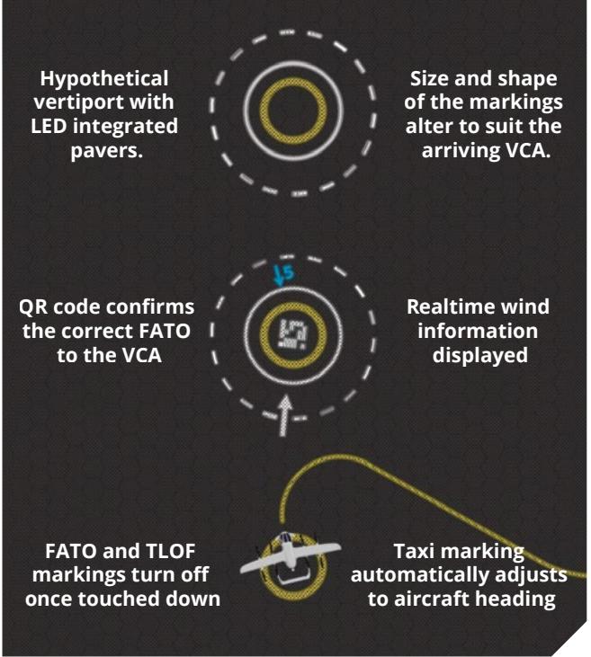
## Example 2:
FATO information could be shared in real time with aircraft operators and aircraft in flight, allowing fine adjustment for departure, flight and arrival time to match the usage of the FATO.
## Example 3:
Future fully-autonomous aircraft may mean that markings and lights will become superfluous. Visual aids are to be seen – by a pilot. Machine readable aids such as QR codes may be used on vertiports to guide aircraft. What will a future vertiport need to be able to guide a VCA safely and accurately?

## Where to from here?
Advisory Circular AC139.V–01 provides greater detail of the design requirements and methods for vertiport design and should be used for actual design work.
CASA has not received (at time of publication) any flight performance documentation from any manufacturers currently developing VCA. We hope the guidance provided in the AC is specific enough to guide vertiport designers and operators in developing a safe and operationally effective facility yet open enough to promote new thinking in this evolving industry.
So, what does this mean for vertiport operators? In short, it means start talking to prospective VCA manufacturers and other stakeholders as soon as possible: the design of the vertiport may take some time.
To even start designing a vertiport, you will need to get a very good understanding of:
the sort of operations you are planning for your vertiport – both initially and in the future
• the types of VCA you want to cater for
how the flight performance of these VCA is going affect the possible flight paths
the obstacle environment that exists around your vertiport
the future development plans in the area and whether they impact the design of the vertiport.
As the industry evolves, new guidance will be produced and current guidance will be updated. Please keep in touch at the CASA emerging technologies program webpage: www.casa.gov. au/resources-and-education/publications-andresources/corporate-publications/emergingtechnologies-program.
Image: Eve Air Mobility
## Appendix A – Acronyms and initialisms
| Term | Definition |
| aerodrome | an area on land or water (including any buildings, installations and equipment) which is authorised under the regulations to be used as an aerodrome for the arrival, departure and movement of aircraft |
| D | for VCA: the diameter of the smallest circle enclosing the aircraft projected on a horizontal plane, while the aircraft is in the take-off or landing configuration, with lift/thrust units turning, if applicable Note: If the aircraft changes dimensions during taxing or parking (for example, folding |
| Design VCA | wings), a corresponding D(taxing) or D(parking) should also be provided a virtual aircraft type that has the largest set of dimensions, the greatest maximum take-off weight (MTOW) and the most critical obstacle avoidance criteria of the aircraft that the vertiport, or for a defined area within the vertiport, is intended |
| Design D | to serve the D of the Design VCA |
| elongated | when used with TLOF or FATO, elongated means an area which has a length more than twice its width |
| final approach and take-off area (FATO) | for the operation of a VCA, a solid area: • from which a take-off is commenced |
| instrument meteorological conditions | • over which the final phase of approach to hover is completed means meteorological conditions other than visual meteorological conditions (see below) |
| obstacle obstacle limitation surfaces | an object (whether temporary or permanent) or part of such an object that: • is located on an area provided for the movement of aircraft • extends above a defined surface designated to protect aircraft in flight a series of planes associated with each FATO at a vertiport, which define the desirable limits to which objects or structures may project into the airspace around the vertiport so that aircraft operations at the vertiport may be conducted safely. The obstacle limitation surfaces are as follows: • FATO protection area (FPA) |
| reference circle a horizontal circle, of the specified dimension, that is centred on any intended position/flight path at or above the applicable area/surface |
| rejected take-off distance required (RTODRV) | the horizontal distance that is required from the start of the take-of to the point where the aircraft comes to a full stop, following a critical failure that is recognised at the to take-off decision point |
| touchdown and lift-off area (TLOF) | an area where a VTOL-capable aircraft may touchdown or lift off |
| touchdown positioning circle (TDPC) | a TDPM in the form of a circle, which is used for omnidirectional positioning in a TLOF |
| touchdown positioning marking (TDPM) | a marking or set of markings that provide visual cues for the directional positioning of an aircraft |
| vertical | a take-off and landing procedure that includes an initial and/or final vertical profile. The profile may or may not include a horizontal component |
| procedure vertical | a surface at which a VTOL-capable aircraft either: |
| procedure | • begins its arriving vertical procedure |
| surface (VPs) vertiport | • ends its departing vertical procedure the highest point of the FATO, or where there are multiple FATOs, the highest point |
| elevation vertiport | of the highest FATO an area of land, water or structure that is used or intended to be used for the landing, take-of and movement of VTOL-capable aircraft |
| vertiports also include vertihubs and vertistops: • vertihub: a vertiport with infrastructure for maintenance, repair, fuelling and |
| |
| vertistop: a vertiport intended for take-off and landing of VCA to drop off or |
| |
| |
| parking spaces for storage of VCA |
| |
| |
| |
| pick up passengers or cargo, but where there are no facilities for fuelling, |
| defuelling, scheduled maintenance, scheduled repairs or storage of aircraft |
| |
| vertiport | a defined horizontal surface selected and/or prepared as a suitable area over |
| |
| clearway | which an aircraft, capable of continued safe flight after a critical failure, may |
| |
| |
| |
| |
| |
| |
| |
| |
| |
| |
| |
| |
| |
| |
| |
| operate between the FATO/VPS and the approach/climb-out surface inner edge |
| |
| |
| |
| |
| |
| |
| |
| |
| |
| |
| visual meteorological conditions | meteorological conditions expressed in terms of visibility, distance from cloud, and ceiling, equal to or better than specified minima |
| VTOL-capable aircraft (VCA) | a heavier-than-air aircraft, other than aeroplane or helicopter, capable of performing vertical procedures by means of more than two lift/thrust units |
| VCA stand | a defined area that is intended to accommodate aircraft for loading or unloading passengers, mail, or cargo, fuelling/charging, parking or maintenance |
| VCA taxi-route | a defined path that is established for the movement of VCA from one part of a vertiport to another: • an air taxi-route: a marked taxi-route that is intended for air taxing • a ground taxi-route: a marked taxi-route centred on a taxiway that is intended for ground movement |
| VCA taxiway | a defined path on a vertiport that is intended for the ground movement of VCA from one part of a vertiport to another |


# 配套专题资料(电力/运行/监管)
# FAA UAM Concept of Operations

Urban Air Mobility (UAM)
PAGE LEFT INTENTIONALLY BLANK

U.S. Department of Transportation Federal Aviation Administration
Office of NextGen
800 Independence Ave., S.W.
Washington, DC 20591
April 26, 2023
Dear Reader:
We are pleased to share Version 2.0 of the Urban Air Mobility (UAM) Concept of Operations (ConOps) with our Federal Aviation Administration (FAA), National Aeronautics and Space Administration (NASA), and industry partners who have provided feedback to Version 1.0 of this document since its release in 2020. This ConOps documents the outcomes of the joint concept development efforts undertaken to date by the FAA NextGen Office with industry stakeholders as well as interagency coordination.
The UAM ConOps Version 2.0 is an iterative progression of work in the development of the concept that will be continued to mature through ongoing government and industry stakeholder collaboration. Future editions of the UAM ConOps will provide a broader and more comprehensive vision of our shared partnership for UAM operations based on feedback and continued collaboration surrounding this iteration of the UAM ConOps.
This document is key element in maturing the overall Advanced Air Mobility (AAM) concept aimed at developing an air transportation system that moves people and cargo between local, regional, intraregional, and urban locations not previously served or underserved by aviation using innovative aircraft, technologies, infrastructure, and operations. AAM will support a wide range of passenger, cargo, and other operations within and between urban and rural environments using new and innovative aircraft.
Sincerely,
Paul Fontaine
Assistant Administrator for NextGen (A)
ANG-1
PAGE LEFT INTENTIONALLY BLANK
## Executive Summary
The Federal Aviation Administration (FAA) NextGen Office released the initial Concept of Operations (ConOps) v1.0 for Urban Air Mobility (UAM) in June 2020 to describe a new, future, operational environment. UAM is a subset of Advanced Air Mobility (AAM), an initiative by the FAA, National Aeronautics and Space Administration (NASA), and industry. The AAM initiative aims to develop an air transportation system that moves people and cargo between local, regional, intraregional, and urban locations not previously served or underserved by aviation using innovative aircraft, technologies, and operations. While AAM supports a wide range of passenger, cargo, and other operations within and between urban and rural environments, UAM focuses on flight operations in and around urban areas. The UAM vision is supported by the introduction of a cooperative operating environment known as Extensible Traffic Management (xTM), which complements the traditional provision of Air Traffic Services (ATS) for future passenger or cargo-carrying operations/flights.
This concept is not a policy statement and is not a prescriptive statement of what the far term integration will be. It is a target description of the evolution of integration from the near-term Innovate 28 environment to a future of high-density urban operations. The concept focuses on a potential longer-term target supporting exploration and validation efforts. Future versions of the ConOps will reflect the outcomes of analyses, trials, concept maturation, and collaboration.
While many of the concept elements are similar across the future cooperative environments (e.g., UAM, Unmanned Aircraft Systems [UAS] Traffic Management [UTM], Upper Class E Traffic Management [ETM]), this ConOps focuses on UAM. The envisioned evolution for UAM operations includes an initial, low-tempo set of operations that leverage the current regulatory framework and rules (e.g., Visual Flight Rules [VFR], Instrument Flight Rules [IFR]) as a platform for increasing operational tempo, greater aircraft performance, and higher levels of autonomy. These are made possible by increased information sharing with operations across a range of environments, including major metropolitan areas and the surrounding suburbs. Resulting from stakeholder input sessions, the mature state operations will be achieved at scale through a crawlwalk-run approach, wherein:
1. Initial UAM operations are conducted using new aircraft types that have been certified to fly within the current regulatory and operational environment.
2. A higher frequency (i.e., tempo) of UAM operations in the future is supported through regulatory evolution and UAM Corridors that leverage collaborative technologies and techniques.
3. New operational rules and infrastructure facilitate highly automated cooperative flow management in defined Cooperative Areas (CAs), enabling remotely piloted and autonomous aircraft to safely operate at increased operational tempos.
This updated UAM ConOps v2.0 reflects the continued maturation of UAM and incorporates feedback received on v1.0, as well as research outcomes and additional input from government and industry stakeholders. Its focus is on clarifying elements from the initial version and providing additional detail in response to the feedback and input.
Language and definitions have been updated to ensure consistency across the cooperative (i.e., xTM) operating environments when applicable and includes an expanded description of Cooperative Operating Practices (COPs) (previously Community Business Rules [CBRs]). However, it does not prescribe specific solutions, detailed operational procedures, or implementation methods except as examples to support a fuller understanding of the elements associated with UAM operations.
Document Change Record
| PublishedDate | DocumentVersion | SectionImpacted | Revisions of Particular Merit |
| 6/26/2020 | 1.0 | Baseline Document |
| 4/26/2023 2.0 | Throughout | Expanded document to provide greater detail ofselected concept elements (e.g., COPs) and relationshipof UAM within the service environments (i.e., ATS andxTM) as well as reconcile use of terms. |
| 1.3 | Updated and expanded service environmentdescriptions to include ATS and xTM. |
| 1.4 | Incorporated definitions for range of terms used acrossthe cooperative environments (e.g., UTM, UAM, AAM,xTM). |
| 3.0, 3.1,3.2, 3.3 | Amended to reflect updated terms and provide greaterdetail on the use of current regulatory framework tosupport initial UAM operations. |
| 4.2 | Addition of section focused on Cooperative OperatingPractices (COPs), which replaces Community BusinessRules (CBRs) |
| 4.3.5 | Updated the phrasing/language describing the federatedservice network supporting UAM operations. |
| 4.4.1, 4.4.2,4.4.3, 4.4.4 | Provided additional detail for elements of UAMCorridors, including potential evolution over time. |
| 5.0 | Updated architecture with additional details (e.g., dataexchanges specific to UAM/PSUs, depiction ofvertiports). |
| 6.0 | Updated scenarios to reflect current content in the bodyof the concept. |
## Table of Contents
Executive Summary .................. ....... iv
1 Introduction ...... ... 1
1.1 Scope.... .. 1
1.2 Background.. ..... 1
1.2.1 Drivers for Change ..... ..... 1
1.2.2 Aircraft Evolution... ..... 2
1.2.3 Vertiport Considerations . .... 2
1.3 Operating Environment Perspectives.. .... 2
1.3.1 Overview ..... ...... 2
1.3.2 UAM Cooperative Environment ........ ............. ....... 3
1.3.3 Operations in the ATS Environment ... ...... 4
1.4 Definitions . .... 4
2 Principles and Assumptions......... ......... 5
3 Evolution of UAM Operations ...... ...... 6
3.1 Initial UAM Operations .. ..... 8
3.2 Midterm Operations. .... 8
3.3 Mature State Operations .. .... 9
4 UAM Operational Concept....... .......... 10
4.1 Overview....... ....... 10
4.2 Cooperative Operating Practices (COPs) . ...... 11
4.3 Roles and Responsibilities ... .... 12
4.3.1 FAA ... ..... 12
4.3.2 UAM Operator ..... ..... 13
4.3.3 Pilot in Command (PIC).. .... 13
4.3.4 Provider of Services for UAM (PSU) . ... 13
4.3.5 Federated Service Network . ..... 15
4.3.6 Supplemental Data Service Provider (SDSP) ... ............. ........ 15
4.3.7 UAM Vertiport ......
4.3.8 UAS Service Supplier (USS) ... ....... 15
4.3.9 Other NAS Airspace Users... .... 16
4.3.10 Public Interest Stakeholders .... ..... 16
4.4 UAM Corridors.. .. 16
4.4.1 UAM Corridor Entry/Exit Points (CEPs). .. 18
4.4.2 Conflict Management and Separation .... ..... 19
4.4.3 Demand-Capacity Balancing (DCB).. ... 19
4.4.4 UAM Corridor Evolution . .. 20
4.5 Weather and Obstacles Within the UAM Environment . .. 22
4.6 Constraint Information and Advisories.. ... 22
5 Notional Architecture....... ..... 23
5.1 Supporting Services ... ..... 24
6 UAM Scenarios .... ... 24
6.1 Nominal UAM Operation Completed Within a UAM Corridor.. .. 25
6.1.1 Planning Phase .. ... 25
6.1.2 In-Flight Phases ... .... 25
6.1.3 Post-Operations Phase.... .... 26
6.2 Nominal UAM Operation Across Service Environments.... .... 26
6.2.1 Planning Phase ... ... 26
6.2.2 In-Flight Phases .. ... 27
6.2.3 Post-Operations Phase. ... 28
7 UAM Evolution ...... ..... 28
Appendix A References...... ..... 29
Appendix B Acronyms... ... 30
Appendix C Glossary ........... .... 32
## List of Figures
Figure 1: Notional Overview of Future Complementary Service Environments . . 3
Figure 2: Evolution of the UAM Operational Environment. .. 7
Figure 3: Notional Multiple UAM Corridors... ... 18
Figure 4: Early UAM Corridor Concept.. .. 20
Figure 5: Use of a Vertical Common Passing Zone ... 21
Figure 6: Use of Lateral Passing Zones .. ... 21
Figure 7: UAM Corridor with Multiple Tracks . .. 22
Figure 8: Notional UAM Architecture.. .. 24
## List of Tables
Table 1: Acronyms... .. 30
Table 2: Glossary .. . 32
## 1 Introduction
## 1.1 Scope
Urban Air Mobility (UAM) enables highly automated, cooperative, passenger or cargo-carrying air transportation services in and around urban areas. UAM is a subset of the Advanced Air Mobility (AAM) concept under development by the Federal Aviation Administration (FAA), National Aeronautics and Space Administration (NASA), and industry. As a subset of AAM, UAM focuses on operations moving people and cargo in metropolitan and urban areas. This Concept of Operations (ConOps) provides an evolving vision that will help facilitate further research on how to best assist UAM operations in the National Airspace System (NAS) if demand and volume exceed current capabilities.
The goal of this ConOps is to provide a common frame of reference to support the FAA, NASA, industry, and other stakeholder discussions and decision-making with a shared understanding of the challenges, technologies, and their potential, as well as examples of areas of applicability to the NAS. No solutions, specific implementation methods, or detailed operational procedures are described in this document except for example purposes (i.e., operational scenarios). This ConOps will be further matured and updated as the concept undergoes validation, stakeholder engagement continues, and additional operational scenarios are developed.
As the follow-on to the UAM ConOps v1.0, this document reflects the outcome of additional stakeholder engagement, exploration, and validation activities. It represents the continued maturation of the vision for UAM operations, airspace considerations, and UAM Cooperative Operating Practices (COPs). The ConOps v2.0 identifies the need for regulatory changes to support operations and collaborative environments with increasing density and complexity.
Current industry projections describe initial UAM operations incorporating a Pilot in Command (PIC) onboard the UAM aircraft with potential evolution to Remote PIC (RPIC). Consistent with the ConOps v1.0 and industry expectations, this document describes operations with an onboard PIC operating within the cooperative environment.
## 1.2 Background
Transportation is constantly evolving. Each step forward yields new opportunities that fundamentally change the relationship that humankind has with distance and travel. While it may not significantly reduce surface traffic volume, UAM will provide an alternative mode of transportation that should reduce traffic congestion during peak times.
## 1.2.1 Drivers for Change
For the UAM concept to mature to operational viability, it is important to understand stakeholder business models and operational needs, as well as their impact, for incorporation into the NAS. The FAA has collaborated with NASA and participated in a series of additional industry stakeholder engagements to identify examples of desired operations and environments for UAM aircraft.
The volume of UAM operations may increase substantially. The degree to which some, or all, of these UAM operations will require current Air Traffic Services (ATS) is undefined. To the degree that these operations require current ATS, the increasing number of UAM operations may soon challenge the current capabilities of the ATS workforce resources. Solutions that extend beyond the current paradigm for crewed aircraft operations to those that promote enhanced shared situational awareness and collaboration among operators are needed. As the FAA continues to mature the UAM concept, additional support systems for UAM operators may be introduced.
To the degree that these operations require current ATS, the increasing number of UAM operations could create new challenges for ATS workforce resources. Several industry leaders and stakeholders have invested heavily in this new concept and technology with the goal of eventually being able to provide the public with personal transportation or cargo services. Personal transportation services may be scheduled, on demand, or part of intermodal transportation links within major urban areas. Greater public acceptance of aircraft integrity and automation in the ride sharing economic model will also help enable increased UAM operations.
## 1.2.2 Aircraft Evolution
The industry vision involves incorporating new aircraft design and system technologies. While some of the new designs may resemble traditional winged aircraft, some are anticipated to include powered lift and Vertical Takeoff and Landing (VTOL) capabilities that facilitate operations between desired locations (e.g., metropolitan commutes). Major aircraft innovations, mainly with the advancement of Distributed Electric Propulsion (DEP) and development of Electric VTOLs (eVTOLs), may allow for these operations to be utilized more frequently and in more locations than are currently performed by conventional aircraft.
## 1.2.3 Vertiport Considerations
State and local governments are being encouraged to actively plan for UAM infrastructure to ensure transportation equity, market choice, and accommodation of demand for their communities. The vertiports and vertistops should be sited to ensure proper room for growth based on FAA evaluated forecasts and be properly linked to surface transportation (when possible), especially if the facility primarily supports cargo operations. Local governments should also have zoning protections in place to protect airspace in and around vertiports and vertistops.
Metropolitan planning organizations, including state and local governments, may incorporate UAM infrastructure planning into larger transportation and utility planning efforts to ensure seamless coverage and capacity. Community engagement and strategic connectivity to larger transportation planning efforts is key to ensuring UAM provides maximum benefits.
## 1.3 Operating Environment Perspectives
## 1.3.1 Overview
NAS operating environments include the airspaces, types of operations, regulations, and procedures necessary to support an operation. Currently, the range of NAS services provided to airspace users are characterized at the highest level under the category of ATS. These include separation (via Air Traffic Control [ATC]), Traffic Flow Management (TFM), advisories, and infrastructure (i.e., Communication, Navigation, and Surveillance [CNS]). Evolving concepts describe the introduction of highly automated, cooperative environments such as Unmanned Aircraft Systems (UAS) Traffic Management (UTM), AAM/UAM, and Upper Class E Traffic Management (ETM) to meet future NAS needs and challenges. These concepts of operations rely on sharing intent information across airspace users. This is governed by the current, evolving regulatory framework as needed to support new types of operations in defined Cooperative Areas (CAs) within which they are conducted.
## 1.3.2 UAM Cooperative Environment
Recent advances in technology have enabled industry development of new and innovative aircraft types, offering lower operating costs and highly automated functionality that facilitates the introduction of new types of operations. At the same time, advances in real-time information sharing and the distribution of roles and functions over federated service networks are maturing daily. In response to these challenges and opportunities, a highly automated, cooperative environment (with defined CAs) relying on a federated service network has been envisioned and described through multiple operational concepts as an additional aspect of the future service environments and part of the NAS. The term Extensible Traffic Management (xTM) is used to refer to these cooperative service environments in general and is comprised of UTM, AAM/UAM, and ETM. UAM operations, as a subset of AAM, may sometimes be conducted in CAs generally described as UAM Corridors. The evolution of the regulatory framework will provide the needed guidance to allow application of the innovative concepts, technologies, and techniques to support the emerging aircraft types and envisioned operations. Figure 1 provides a depiction of the AAM/UAM environment (outlined in red) relative to the current service delivery environment, as well as the other future cooperative environments.
As part of the future NAS, the complementary service delivery environments (i.e., ATS and xTM) will be evaluated as potential options to assist with scalability to meet future demand challenges and the flexibility to seize opportunities presented by the rapid evolution across the technology horizon (e.g., cloud computing, communications, information management).
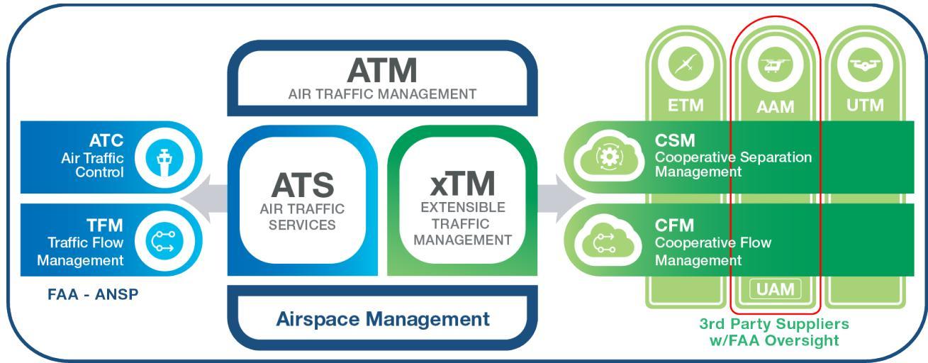
Figure 1: Notional Overview of Future Complementary Service Environments
## 1.3.3 Operations in the ATS Environment
All aircraft are required to comply with the regulatory requirements of the airspace within which they are conducting operations. A UAM operation is one executed by a UAM aircraft conducted within an airspace volume defined for UAM cooperatively managed operations. When conducting operations in the ATS environment, a UAM aircraft will comply with the ATS requirements of the applicable airspace class.
UAM aircraft will need to comply with applicable ATS regulations regarding VFR and IFR while operating in either Visual Meteorological Conditions (VMC) or Instrument Meteorological Conditions (IMC), like any current NAS operation. Capable aircraft (and operators) may choose to utilize ATS operating outside of a CA or cooperative services if operating in a CA based on whichever is more operationally advantageous to the airspace user. Consistent with today’s operations, this choice is subject to the environment and conditions for the flight.
## 1.4 Definitions
Automated Flight Rules (AFRs) – Refers to rules, applied within UAM Corridors, which reflect the evolution of the current regulatory regime (e.g., VFR/IFR) and take into account advancing technologies and procedures (e.g., Vehicle-to-Vehicle [V2V] and data exchanges). Under defined conditions, the systems/automation may be allocated the role of the “predetermined separator” (see paragraphs 2.7.18–2.7.22 in [1]).
Cooperative Area – An airspace volume (e.g., UAM Corridor) within which cooperatively managed operations can occur. ATC ensures separation of non-participating aircraft from the cooperative operations and/or CA.
Cooperative Operating Practices (COPs) – Industry-defined, FAA-approved practices that address how operators cooperatively manage their operations within the CA (i.e., UAM Corridor), including conflict management, equity of airspace usage, and Demand-Capacity Balancing (DCB).
Cooperative Operation – A term used to describe an operation making use of cooperative services (e.g., separation, flow management) and is sharing/exchanging Operational Intent and other information in compliance with applicable regulations and COPs within a CA.
Federated Service Network – A group of service providers sharing information within a federated network to support operating in a common, agreed manner consistent with the approved COPs.
Fully Integrated Information Environment – Information environment and key attributes necessary to effectively deliver services and facilitate information exchange between stakeholders.
Service Environment(s) – Refers collectively to the distinct regulatory, procedural, and supporting automation mechanisms through which services (e.g., conflict management, flow management) are provided. In the future, the NAS is envisioned to include the current (i.e., traditional) ATS environment as well as incorporate a complementary, cooperative xTM services environment.
UAM Aircraft – An aircraft that chooses to participate in UAM operations.
UAM Corridor – A specific type of CA, as an airspace volume within which cooperatively managed operations can occur. ATC ensures separation of non-participating aircraft from the cooperative operations and/or CA. It is comprised of an airspace volume defining a threedimensional route, possibly divided into multiple segments, with associated performance requirements.
UAM Operation – A specific type of cooperative operation that occurs within a UAM Corridor and is conducted in compliance with UAM specific rules, procedures, performance requirements, and COPs.
UAM Operator – The person or entity responsible for the overall management and execution of one or more UAM operations. The operator plans operations, shares flight information (e.g., planning, live flight), and ensures infrastructure, equipment, and services are in place to support safe execution of flight. Throughout this document, “UAM operator” is often used to describe the roles and responsibilities of the UAM Code of Federal Regulations (CFR) Title 14, Part 135 carrier, the RPIC/PIC, or conflict management automation to avoid allocating prematurely and allow for evolution of the role.
Vertiports – A collective term for the diverse system of public and private vertiports and vertistops.
Vertiport – An area of land or structure used or intended to be used for electric, hydrogen, and hybrid VTOL landings and takeoffs. A vertiport can include associated buildings and facilities.
Vertistop – A vertistop is a term generally used to describe a minimally developed vertiport for boarding and discharging passengers and cargo (i.e., no fueling, defueling, maintenance, repairs, or storage of aircraft, etc.).
## 2 Principles and Assumptions
The following principles and assumptions guide the development of the UAM operating environment and mature the UAM concept.
• The FAA retains regulatory authority over NAS airspace and operations.
o UAM aircraft operate within a regulatory, operational, and technical environment as part of the NAS.
o Any evolution of the regulatory environment will always maintain safety of the NAS.
• The FAA reserves the right to increase aircraft operational performance requirements to optimize the capacity/utilization of the airspace.
• The FAA has on-demand access to information regarding UAM operations.
• Airspace management will be static where necessary and flexible when possible.
• UAM operators:
o Are responsible for the coordination, execution, and management of their operations.
o Conduct operations in compliance with the applicable regulatory framework for the operation, the airspace within which the operation is conducted, and the applicable COPs.
O Maintain conformance to shared intent and, via Providers of Services for UAM (PSUs), are made aware of the intent of other relevant operations.
o Cannot optimize their own operations at the expense of sub-optimizing the environment as a whole.
Cooperative traffic management is conducted in compliance with a set of COPs, which would need to be collaboratively developed by relevant stakeholders and approved by the government.
o DCB intervention may be required as the number of UAM operations increases.
o As the operational tempo increases the need for new ATC tactical deconfliction techniques, including the formulation of new separation standards that would rely on enhanced aircraft performance and air traffic management system fidelity may be utilized.
o The architecture (i.e., technology) for UAM services needs to be flexible and scalable. Operators or third-party service suppliers share information using common standards and messaging protocols to ensure interoperability.
• PSUs may be utilized by operators to receive and exchange information during UAM operations.
## 3 Evolution of UAM Operations
The evolution of UAM operations is characterized by the following key indicators.
1. Operational Tempo: Representation of the density, frequency, and complexity of UAM operations. Tempo evolves from a small number of low-complexity operations to a highdensity, high frequency of complex operations.
2. UAM Structure (Airspace and Procedural): The level of complexity of infrastructure and services that support the UAM environment.
3. UAM-Driven Regulatory Changes: Existing regulations may need to evolve to address the needs for UAM operations’ structure and performance.
4. UAM COPs: COPs implement the updated regulations to establish the expectations and interactions. See Section 4.2 for additional COP details.
5. Aircraft Automation Level: The level of “PIC” engagement with the UAM aircraft enabling systems. The following categories describe the evolution of aircraft automation:
Human-Within-the-Loop (HWTL)
o Human is always in direct control of the automation (i.e., systems)
Human-on-the-Loop (HOTL)
o Human has supervisory control of the automation (i.e., systems)
o Human actively monitors the systems and can take full control when required or desired
Human-Over-the-Loop (HOVTL)
o Human is informed, or engaged, by the automation (i.e., systems) to take action
o Human passively monitors the systems and is informed by automation if, and what, action is required
o Human is engaged by the automation either for exceptions that are not reconcilable or as part of rule set escalation
6. Location of the PIC: The physical location of the PIC. UAM operations may evolve from a PIC onboard the UAM aircraft to RPICs/remote operators via the advent of additional aircraft automation technologies.
Figure 2 describes the evolution of UAM operations and its relationship with increasing level of operational tempo and the airspace structure and procedures.
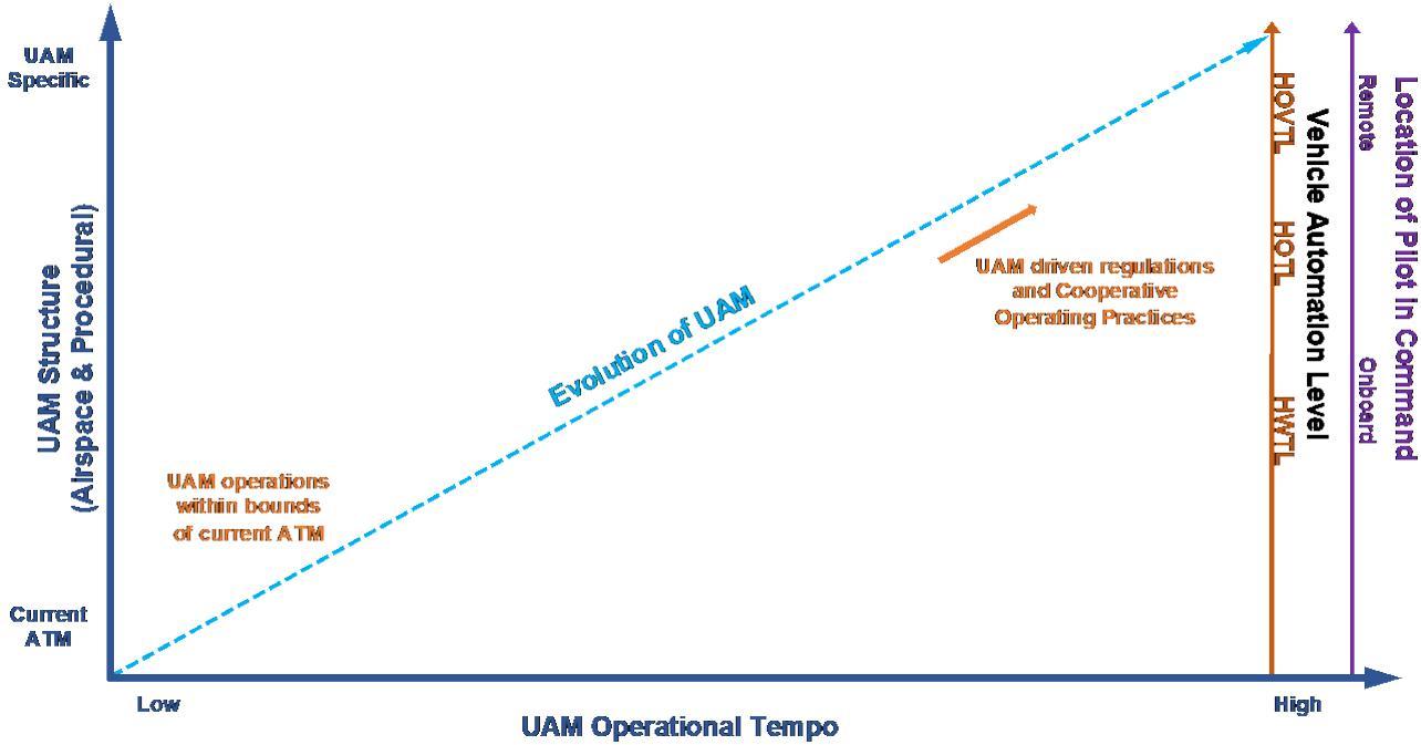
Figure 2: Evolution of the UAM Operational Environment
UAM operational evolutionary stages are described in the following subsections:
Initial UAM operations
• Midterm operations
• Mature state operations
## 3.1 Initial UAM Operations
Initial UAM operations are conducted by UAM aircraft leveraging current ATS rules and regulations (e.g., VFR, IFR). Key indicators of initial UAM operations are listed below.
Operational Tempo: Low.
UAM Structure (Airspace and Procedural): No UAM unique structures or procedures exist. Operations will utilize existing ATS and routes but may create new routes as necessary.
UAM-Driven Regulatory Changes: Initial UAM operations are conducted leveraging current rules, regulations, and local agreements.
• UAM COPs: There are no COPs, but operational needs may be addressed in agreements such as Letters of Agreement (LOAs).
• Aircraft Automation Level: Consistent with current, crewed fixed-wing and helicopter technologies (e.g., autopilots, auto-land).
• Location of the PIC: Onboard.
For UAM aircraft that are capable, current operations are supported by existing rules, procedures, and designated routes. As additional operations outside of the current operational paradigms are initiated, LOAs, routes, and other procedural changes may need to be introduced to accommodate the additional demand and location of operations within the regulatory framework of the current ATS system. Since industry anticipates increasing operations to scale cost effectively and meet increased demand for services, the demand for UAM operations may eventually reach the limits of current regulations and ATS services.
## 3.2 Midterm Operations
With increased tempo, UAM operations will evolve through changes to the governing regulations augmented by COPs, UAM infrastructure, and automation. The evolution to a collaborative, information-rich, data-sharing environment may require new technologies and capabilities. UAM operators and other stakeholders will share information with the FAA, having on-demand access to identified operational information.
Midterm operations are supported by an environment that meets the needs of increased operational tempo. Key indicators of midterm UAM operations are listed below.
Operational Tempo: The operational tempo remains low; however, it may have increased to a point that necessitates changes in the existing regulatory framework and procedures.
UAM Structure (Airspace and Procedural): UAM aircraft are flying within UAM Corridors. UAM operations are enabled through confirmed UAM Operational Intent— operation-specific information including, but not limited to, UAM operation identification, the intended UAM Corridor(s), aerodromes and vertiports, and key operational event times (e.g., departure, arrival) of the UAM operation. Operations are considered UAM participants during the period of operation that exists within the UAM Corridor cooperative environment.
ATC ensures separation of non-participating aircraft from cooperative operations and/or CAs.
Deconfliction may be allocated to the UAM operator and/or PIC akin to visual separation.
UAM-Driven Regulatory Changes: Changes to ATS regulations and new UAM regulations that enable operations within UAM Corridors.
UAM COPs: COPs are defined by industry to meet industry standards or FAA guidelines when specified. COPs will require FAA approval.
• Aircraft Automation Level: PICs may control the aircraft with emerging capabilities (e.g., simplified vehicle operation).
• Location of the PIC: Primarily onboard aircraft but complemented by the introduction of RPIC operations (with one RPIC per operation).
The number and complexity of operations, along with aircraft capabilities and equipage, may increase beyond that effectively supported by leveraging current rules (e.g., VFR, IFR). To support such an increase, a UAM cooperative environment may need to be developed and implemented with new or modified procedures, an updated regulatory framework, and COPs. The UAM cooperative environment (i.e., UAM Corridor) is a performance-based airspace structure with defined parameters that are achievable by the participants. UAM Corridors would be known to airspace users and governed by a set of rules which prescribe access and operations. Where supporting infrastructure and support services meet participation requirements, UAM operations may be conducted. Operators whose aircraft meet performance and participation requirements may conduct operations within the UAM Corridor.
Initially, the number of UAM Corridors may be low or limited in use, but over time, additional UAM Corridors may be introduced as they may be utilized in airspace areas where traffic volume requires their establishment in the interest of safety and efficiency. The UAM Corridors may transit any applicable airspace classes.
Operations within UAM Corridors may be supported by COPs collaboratively developed by the stakeholder community, based on industry standards and/or FAA guidelines, and approved by the FAA, as appropriate, to ensure that the agency’s regulatory authority is maintained (e.g., NAS safety, equitable access, security). The collaborative development of COPs would allow for stakeholders to agree on norms of interactions, which may reduce the need for ATC tactical control of individual flights and management of access. The collaboratively developed, transparent, standard COPs augment the envisioned regulatory foundation for UAM operations.
## 3.3 Mature State Operations
As the UAM operational tempo increases, UAM operations may further evolve to support operational demand. Key indicators of mature state UAM operations are listed below.
Operational Tempo: The operational tempo increases significantly. Higher operational tempo needs drive the increased maturity for the other indicators.
UAM Structure (Airspace and Procedural): UAM operations continue to occur within UAM Corridors. The UAM Corridors may form a network to optimize paths to support an increasing number of vertiports; the internal structure of the UAM Corridors is expected to increase in complexity, and the necessary performance parameters for UAM participation may increase. ATC ensures separation of non-participating aircraft from cooperative operations/CAs. Deconfliction may be allocated to the UAM operator, PIC, or operator’s automation.
• UAM-Driven Regulatory Changes: Extensive UAM-driven regulations will be necessary to enable cooperative operations within UAM Corridors.
UAM COPs: The complexity of COPs and FAA involvement in establishing guidelines and approving COPs may evolve to match the specific topic addressed.
• Aircraft Automation Level: Automation improvements may lead to HOVTL capabilities.
• Location of the PIC: Remote piloting is more widely available and as frequent as PIC operations.
Additional increases in the tempo of midterm operations could require advances to the UAM environment and aircraft. To overcome the constraints, UAM operations may evolve to UAM mature state operations through advances to data sharing, DCB, UAM structure, and aircraft automation. Mature state operations may also include additional COPs accompanied by UAMdriven regulatory changes.
## 4 UAM Operational Concept
This section provides an overview of the UAM operational concept and COPs, followed by key definitions and descriptions of roles and responsibilities, UAM Corridor characteristics, weather and other obstacles within the UAM environment, and constraint information and advisories.
## 4.1 Overview
A UAM operator performing a UAM operation is cooperatively sharing information and engaging cooperative services to assure the safe and efficient conduct of the flight within a UAM Corridor. The UAM Corridor structure, UAM procedures, information sharing, and UAM performance criteria enable increasing operational tempo and minimize impact to ATS. UAM operations are supported by PSUs that comprise a federated service network to enhance the capabilities of individual UAM operators/PICs in all phases of operations through exchange, analysis, and mediation of information among all relevant actors (e.g., UAM operators/PICs, PSUs, the FAA, and public interest stakeholders).
Any aircraft operating within a UAM Corridor must meet the performance and participation requirements of the UAM environment. Within UAM Corridors, deconfliction is allocated by ATC to UAM operators and/or PIC. The UAM community will collaboratively develop and establish COPs as standards for operations. The FAA may contribute to COP guidelines but will approve COPs based on the specific focus, topic, or area addressed by the COP. UAM Corridor design, performance, and participation requirements, as well as UAM COPs, may be designed to reduce ATC involvement with UAM off-nominal events by implementing standardized off-nominal protocols. UAM aircraft operating outside UAM Corridors must follow the operational rules and procedures applicable to the corresponding airspace.
The concept represents an early step in the envisioned evolution of the regulatory framework, development of operating rules and performance requirements commensurate with demands of the operation, and data exchange with information architecture to support UAM operator and FAA responsibilities. UAM leverages a common, shared, technical environment, where the operators are responsible for coordination, execution, and management of operations consistent with the regulatory framework and applicable COPs. This networked information exchange is the cornerstone for stakeholders to plan, manage, execute, and oversee UAM operations. Additional stakeholders can access UAM shared operational information on demand.
## 4.2 Cooperative Operating Practices (COPs)
Foundational to the success of the envisioned, federated, highly automated, cooperative environment is the establishment of common business rules across relevant stakeholders, referred to as COPs. Development, adoption, and implementation of COPs will require collaboration across multiple stakeholders—including operators, industry, and the FAA as the regulator—to identify and resolve a broad range of questions and challenges. Examples of these questions include “what rules are needed?”, “how are they expressed?”, and “how will they be managed?”
COPs are characterized as industry-defined, FAA-approved practices that address how operators cooperatively manage their operations within the cooperative UAM environment, including conflict management, equity of airspace usage, and DCB.
They are consistent with and augment updates to the regulatory framework. 1 The development timeframe will be driven by the pace at which operators desire to execute cooperative UAM operations distinct from those conducted under the current regulatory framework (e.g., VFR, IFR). As the tempo and complexity of UAM operations increases, it is anticipated that the complexity and range of topics covered by COPs will also increase. The relationship between industry and government (e.g., FAA, Department of Transportation [DOT]) differs based on the focus of the specific COP. In some instances, the rules or topic area of an individual COP may determine the level of engagement necessary with the regulatory authority. The level of engagement also has implications for the level of involvement that the authority will undertake as part of the applicable coordination for the specific COP. The range of engagement by the regulator may span from minimal to high levels. At higher levels, significant documentation, and testing, as well as formal acceptance, authorization, or qualification, may be necessary prior to operational use by industry.
Another aspect of the relationship between government and industry before a specific COP may be used operationally is “equity interest.” This refers to how closely the topic/area covered by the specific COP is related to government responsibilities (i.e., mission) or policies. Some COPs, such as those focused on aviation safety, fall directly under the FAA’s regulatory mission. Other COPs, such as avoiding unnecessary anti-competitive technical specifications for participation in the federated service network, may be subject to policies that fall under the purview of regulatory agencies beyond the FAA.
## 4.3 Roles and Responsibilities
This section defines the roles and responsibilities for actors associated with UAM operations.
## 4.3.1 FAA
The FAA performs regulatory, ATC, and NAS data exchange roles for UAM, as detailed in the following subsections.
## 4.3.1.1 Regulation
The FAA is the federal authority over aircraft operations in all airspace and the regulatory and oversight authority for civil operations in the NAS. The FAA maintains an operating environment that ensures airspace users have access to the resources needed to meet specific operational objectives and that shared use of the airspace can be achieved safely and equitably. The FAA develops or modifies regulations to support UAM operations. The FAA will approve COPs to ensure that the FAA authority is maintained (e.g., NAS safety, equal access to airspace, security). The FAA will define, maintain, and make publicly available UAM Corridor definitions (e.g., routes and altitudes) and manage the performance requirements of UAM Corridors.
## 4.3.1.2 ATC
The primary purpose of ATC is to maintain safe movement of aircraft operating within the NAS. For high-density UAM operations, this may be accomplished through ATM modernization. ATC will ensure the separation of non-participating aircraft from the cooperative operation and/or CAs. As appropriate, ATC may issue traffic advisories regarding known UAM operations (e.g., active UAM Corridors) to aircraft receiving ATC services. ATC may request information as needed from participating actors and may receive automated notifications in accordance with applicable requirements.
The ATC responsibilities that enable UAM operations are to:
1. Set UAM Corridor availability (e.g., open or closed) based on operational design (e.g., time of day, flow direction of a nearby airport).
2. As appropriate, provide traffic advisories regarding known UAM operations (e.g., active UAM Corridors) to aircraft receiving ATC services.
3. Respond to UAM off-nominal operations as needed.
4. When tactical separation assurance is required, provide current or newly developed services appropriate to the airspace in which the UAM aircraft is operating.
To fulfill their responsibilities, ATC may review any pertinent information from UAM operations.
## 4.3.1.3 NAS Data Exchange
FAA NAS data sources are available to UAM operations via FAA-industry exchange protocols.
This allows for authorized data flow between the UAM community and FAA operational systems.
This interface between the FAA and UAM stakeholders is a gateway such that external entities do not have direct access to FAA systems and data. FAA data sources available via the FAA-industry data exchange include, but are not limited to, flight data, restrictions, charted routes, and active Special Activity Airspaces (SAAs).
## 4.3.2 UAM Operator
UAM operators may conduct operations as scheduled services or on-demand services via a request from an individual customer or intermodal operator. UAM operators are responsible for regulatory compliance and all aspects of UAM operation execution. Use of the term “UAM operator” in this document indicates airspace users electing to conduct operations via cooperative management within the UAM environment.
The UAM operator obtains current conditions from PSU and Supplemental Data Service Provider (SDSP) services (e.g., environment, situational awareness, strategic operational demand, vertiport availability, supplemental data) to determine the desired UAM Operational Intent information. This may include location of flight (e.g., vertiport locations), route (e.g., specific UAM Corridors), UAM Corridor entry or exit point, and estimated flight time.
UAM operators must have a confirmed UAM Operational Intent to operate in UAM Corridors.
UAM Operational Intent data serves the following primary functions.
1. Informs other UAM operators of nearby operations within the UAM Corridor to promote safety and shared awareness
2. Enables strategic deconfliction
3. Enables identification and distribution of known airspace constraints and restrictions for the intended area of operation
4. Enables distribution of spatially and temporally relevant advisories, weather, and supplemental data
5. Supports cooperative separation management services (e.g., conformance monitoring, advisory services)
The UAM operator also plans for off-nominal events. This includes an understanding of alternative landing sites and the airspace classes that border the UAM Corridor(s) for the operation. Upon completion of the operation, the UAM operator notifies the PSU.
## 4.3.3 Pilot in Command (PIC)
The PIC is the person aboard the UAM aircraft who is ultimately responsible for the operation and safety during flight. This ConOps assumes a pilot onboard the aircraft; however, operations described do not preclude a remote pilot or automated operations.
## 4.3.4 Provider of Services for UAM (PSU)
A PSU is an entity that supports UAM operators with meeting UAM operational requirements that enable safe, efficient, and secure use of the airspace. A PSU is the primary service and data provider for UAM stakeholders and the interface between the UAM ecosystem and the FAA. A PSU can be a separate entity from the UAM operator, or an operator can act as its own PSU. When confirming the UAM Operational Intent, a PSU may act on behalf of an operator who has subscribed to its offered services within the updated regulatory framework established by the FAA for instances when an operator does not act as its own PSU.
## A PSU:
1. Provides a communication bridge between federated UAM actors, from PSU to PSU via the network, to support its subscribing UAM operator’s ability to meet the regulatory and operational requirements for UAM operations.
2. Provides its UAM operators with information gathered from the network about planned UAM operations in a UAM Corridor so that UAM operators can ascertain the ability to conduct safe and efficient missions.
3. Analyzes and confirms that a submitted UAM Operational Intent is complete, consistent with current advisories and restrictions, and strategically deconflicted considering previously confirmed UAM Operational Intents, COPs, UAM Corridor capacity, airspace restrictions, vertiport resource availability, and adverse environmental conditions.
4. Provides the confirmed UAM Operational Intent to the federated service network.
5. Distributes notifications (e.g., constraints, restrictions) for the intended area of operation.
6. Distributes FAA operational data and advisories, weather, and supplemental data.
7. Supports cooperative separation management services (e.g., conformance monitoring, advisory services).
a. Assists with coordinating UAM Corridor use status; UAM Corridor use status (e.g., occupied, unoccupied) is an indication that UAM operations are being conducted or not.
8. Archives operational data in historical databases for analytics, regulatory, and UAM operator accountability purposes.
9. Negotiates airport access through the airport’s sponsor.
These key functions allow a PSU to support cooperative management for UAM operations without direct FAA involvement on a per flight basis.
PSU services support operations planning, UAM Operational Intent sharing, deconfliction, airspace management functions, and off-nominal operations that UAM operators may encounter. PSUs may provide value-added services to subscribers that optimize operations or provide SDSP services in support of UAM operations. PSUs exchange information with other PSUs via the federated service network to enable UAM services (e.g., exchange of UAM Operational Intent information, notification of UAM Corridor status, information queries). PSUs also support local municipalities and communities as needed to gather, incorporate, and maintain information that may be accessed by UAM operators.
## 4.3.5 Federated Service Network
The federated service network is the collection of connected PSUs that share subscriber information, FAA data, supplemental data, and data from other entities (e.g., PSUs, FAA, public interest stakeholders) to provide a fully integrated information environment to support UAM operations. Since multiple PSUs can provide services in the same geographical area, the federated service network facilitates the availability of data to the FAA and other entities as required to ensure safe operation of the NAS and any other information sharing functions including security and identification.
## 4.3.6 Supplemental Data Service Provider (SDSP)
UAM operators and PSUs use supplemental data services to access supporting data including, but not limited to, terrain, obstacle, and specialized weather. PSUs are also able to serve as SDSPs for subscribed UAM operators. SDSPs may be accessed via the federated service network or directly by UAM operators.
## 4.3.7 UAM Vertiport
Vertiports, used as a collective term, are expected to be a diverse system of public and private vertiports and vertistops. These facilities are categorized to identify the variety of aircraft they can support based on facility design and operations. Vertiports and vertistops support passenger and cargo operations for aircraft operating in VFR, IFR, and AFR.
UAM operators are expected to utilize whichever vertiport configuration meets their operational needs.
A vertiport is a designated area that meets the capability requirements to support UAM departure and arrival operations. The UAM vertiport provides current and future resource availability information for UAM operations (e.g., open/closed, pad availability) to support UAM operator planning and PSU strategic deconfliction. UAM vertiport information is accessible by the operator via the federated service network and supplemental vertiport information may be available via the SDSP. The vertiport information is used by UAM operators and PSUs for UAM operation planning including strategic deconfliction and DCB; however, the vertiports do not provide strategic deconfliction or DCB services.
## 4.3.8 UAS Service Supplier (USS)
UAS Service Suppliers (USSs) are entities that support UAS operations under the UTM system (see the UTM ConOps v2.0 [2] for more details). Potential scenarios may exist where USSs and PSUs need to share information to ensure cooperative separation during UAM landing and takeoff phases of flight within UTM environments (i.e., under 400 feet).
From a UAM operational perspective, USSs may interact with PSUs by:
1. Enabling UTM operations to use federated service network services to cross a UAM Corridor.
2. Supporting UAM off-nominal operations as needed (e.g., UAM operations executing emergency landings impacting UTM operation areas).
3. Supporting UTM off-nominal operations as needed (e.g., UTM operation deviating from filed Operational Intent near a UAM vertiport).
## 4.3.9 Other NAS Airspace Users
Other NAS airspace users are any non-UAM aircraft operation within the NAS. These users would have the responsibility to know about and meet the relevant performance and participation requirements to operate in open UAM Corridors or avoid active UAM Corridors. UAM Corridor definitions and availability will be publicly available for these users to access.
## 4.3.10 Public Interest Stakeholders
Public interest stakeholders are entities declared by governing processes (e.g., COPs) to be able to access UAM operational information and notifications. This access may support activities including, but not limited to, public right to know, government regulatory, government assured safety and security, and public safety. Examples of public interest stakeholders are local law enforcement and United States federal agencies.
## 4.4 UAM Corridors
As described earlier, initial UAM operations are expected to make use of the flexibility in the current regulatory framework (e.g., VFR, IFR) to meet their operational and mission needs. Over time, the number of UAM operations are expected to increase, the specific areas/locations where operators desire to conduct the operations may expand, and aircraft capabilities (e.g., equipage, performance) could advance. Corridors may offer the opportunity to respond to what could be new levels and types of service demands while taking advantage of the aircraft’s capabilities without adversely impacting current service levels.
The concept of UAM Corridors envisions safe and efficient UAM operations that may not require traditional ATC services in certain situations, are available to any aircraft appropriately equipped to meet the performance requirements, and would be created/implemented when operationally advantageous. The UAM Corridors could help support the increasing operational tempo through increased capabilities (e.g., aircraft performance), UAM Corridor structure, and UAM procedures. At increased UAM traffic levels, UAM Corridors could be a mechanism for distinguishing and keeping separate the different regulatory frameworks—those applicable to UAM operations versus those operating under the current (e.g., IFR, VFR) or UTM regulations.
UAM Corridors would be designed consistent with applicable environmental considerations and may be implemented in areas where it is operationally advantageous. The UAM Corridors may transit all airspace classes. It is anticipated that UAM Corridors may exist simultaneously at locations and in airspace classes with constructs (e.g., VFR flyways/corridors, IFR) leveraged for initial UAM operations.
Operations within UAM Corridors may have operational performance and participation (e.g., UAM Operational Intent sharing, deconfliction within the UAM Corridor) requirements. The performance and participation requirements for a UAM Corridor may vary between UAM Corridors. In addition, performance requirements and UAM Corridor definition (e.g., volume, location) support accommodations for most UAM off-nominal operations where the UAM aircraft can complete the operation safely. Any operator meeting the UAM Corridor performance and participation requirements may operate within or crossing the UAM Corridor. The crossing of a UAM Corridor by an aircraft/operator not participating in the cooperative environment (e.g., general aviation) remains an area of exploration as the UAM Corridor concept, specific features, uses, and requirements mature. As UAM Corridor geometry is better understood, the foundational elements of UAM Corridor crossings may be analyzed by stakeholders.
UAM Corridor definitions are available to stakeholders for planning and operational use. ATC will be involved in the implementation and execution of UAM Corridors for the airspace for which ATC is responsible. Other NAS users will be aware of UAM Corridors through airspace familiarization associated with flight planning or ATC flight plan approval or advisories. UAM Corridor design considerations should include:
1. Minimal impact to existing ATS and UTM operations while maintaining equity for all operators.
2. Public interest stakeholder needs (e.g., local environmental and noise, safety, security).
3. Stakeholder utility (e.g., customer need).
UAM Corridor availability (e.g., open, closed) would be in accordance with ATC operational design (e.g., nearby airport configurations/change). UAM Corridor availability may be communicated through the federated service network to PSUs and UAM operators. In addition to UAM Corridor availability established by ATC, PSUs determine UAM Corridor status that identifies if one or more UAM operations are occurring somewhere within the UAM Corridor. UAM Corridor usage information may be used by the FAA or other stakeholders for situational awareness.
Initially, the UAM Corridors may support point-to-point UAM operations. As UAM operations evolve, UAM Corridors may be segmented and connected to form more complex and efficient networks of available routing between points (e.g., vertiports). Figure 3 shows a small number of point-to-point UAM Corridors.
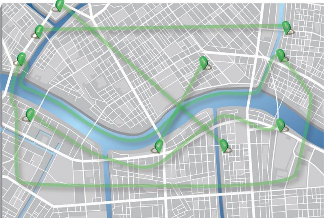
Figure 3: Notional Multiple UAM Corridors
## 4.4.1 UAM Corridor Entry/Exit Points (CEPs)
Some UAM operations may be conducted wholly within the cooperative environment. However, most operations are anticipated to transit both service environments (i.e., ATS and xTM [UAM]). Corridor Entry/Exit Points (CEPs) refer to the defined points in space at which an aircraft crosses from one environment to another.
CEPs may be “established” in that they are defined as part of the UAM Corridor itself. An example would be established points at either end of a UAM Corridor that are defined and disseminated as part of the UAM Corridor definition/description. They may also be “operation-defined,” which are those points in space on the boundary between the service environments (i.e., ATS and xTM [UAM]) along an accepted intent or trajectory that has not already been established.
Specific requirements or limitations regarding the use of CEPs may be addressed in applicable COPs and regulatory framework. Aircraft entering or exiting a UAM Corridor must meet the requirements of the airspace (e.g., Class B, C, D, E) they intended to use external to the UAM Corridor.
## 4.4.2 Conflict Management and Separation
Conflict management across the NAS includes the strategic activity of airspace organization and management. In certain situations, when operationally advantageous, UAM Corridors may enable UAM operations without traditional ATC services. Separation of operations within UAM Corridors may be provided through a layered approach of strategic and tactical deconfliction methods. Strategic deconfliction envisions the sharing of flight intent and the collaborative execution of the COPs relevant to deconfliction. In later stages, capabilities relying on V2V data exchanges guiding the execution of aircraft separation may also mature sufficiently for implementation.
When operating within a UAM Corridor, FAA regulations and COPs direct the manner of interactions across relevant actors for strategic and tactical deconfliction. UAM operators remain responsible for the safe conduct of operations, including operating relative to other aircraft, weather, terrain, and hazards and avoiding unsafe conditions. UAM separation is achieved via shared UAM Operational Intent, shared awareness, strategic deconfliction of flight intent, and the establishment of procedural rules.
While strategic deconfliction within UAM Corridors could occur during UAM Operational Intent planning, the need may remain for in-flight coordination, sharing, and tactical deconfliction. Initial analysis indicates strategic deconfliction in the planning phase may not be sufficient to support the operational tempo described as desired by industry. In the event a UAM aircraft operates outside of the bounds of shared UAM Operational Intent, notifications of the off-nominal event and updates to the UAM Operational Intent, if applicable, would be shared via the federated service network. Initial separation in UAM Corridors may leverage applicable VFR/IFR mechanisms (e.g., “see-and-avoid”). If aircraft technology and capabilities (e.g., equipage) evolve and mature, separation minima and AFRs may be introduced to provide higher capacity and support the projected increase in demand (i.e., operational tempo). The regulatory framework governing UAM operations would need to evolve significantly to account for the increasing levels of performance and automation. The maturation and implementation of both the advanced technologies and updated regulatory framework are coupled to changes in the separation minima and, by extension, the available throughput of a given UAM Corridor. The need for DCB capabilities or initiatives will be coupled to the pace at which the operational tempo increases and the envisioned advances in aircraft performance (e.g., equipage, capabilities) are realized.
## 4.4.3 Demand-Capacity Balancing (DCB)
DCB is applied when the requested resources cannot support the collective UAM Operational Intent demand. In certain circumstances, the excessive demand may not be due to UAM Corridor capacity but due to other factors such as congestion at origin or destination. Initial analysis of strategic deconfliction to eliminate tactical maneuvering identified that the operational tempo desired by UAM operators cannot be supported solely through strategic planning/deconfliction. The “buffer” necessary to account for uncertainty as the operational tempo increases leads to the eventual need for tactical deconfliction and DCB capabilities to optimize efficiency.
Within the UAM Corridor, flow management functions, including DCB, will be provided through Cooperative Flow Management (CFM) services. The business rules governing the execution of
CFM are included in relevant COPs, which are consistent with FAA authority including access, equity, safety, and security.
## 4.4.4 UAM Corridor Evolution
Initial UAM operations, characterized by low tempo and low complexity, will be executed using the current regulatory framework. As the tempo and complexity of operations increases, options available in the current regulatory framework (e.g., VFR corridors/flyways, T-routes) may accommodate the growth. As the operations continue to increase in volume and complexity, the implementation of simple UAM Corridors may become operationally advantageous for the airspace users and/or the ATS service providers. Initial UAM Corridors are expected to be “simple” in design (e.g., one-way UAM Corridors or single track in each direction), as illustrated in Figure 4. As UAM Corridors become more defined, AFR will likely be available, consistent with the evolving regulatory framework.
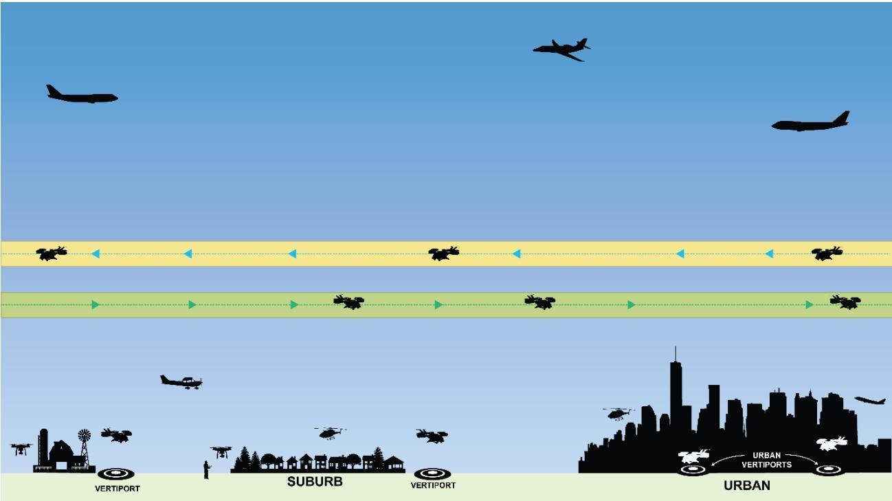
Figure 4: Early UAM Corridor Concept
With continued growth, UAM operational demand may result in exceeding a UAM Corridor’s initial design capacity, at which point increased capacity may be gained through additional structure including tracks and increased performance capabilities (e.g., ability to safely reduce separation minima within the UAM Corridor through improvements in navigation and/or other technologies). Additional options include variations in UAM Corridor topology to meet specific challenges such as “passing zones” as shown in Figure 5 and Figure 6. Note: An aircraft (and operator) meeting the performance requirements of a UAM Corridor as well as those of the surrounding airspace class (i.e., ATS environment) may elect to operate in whichever service environment they determine to be operationally advantageous.
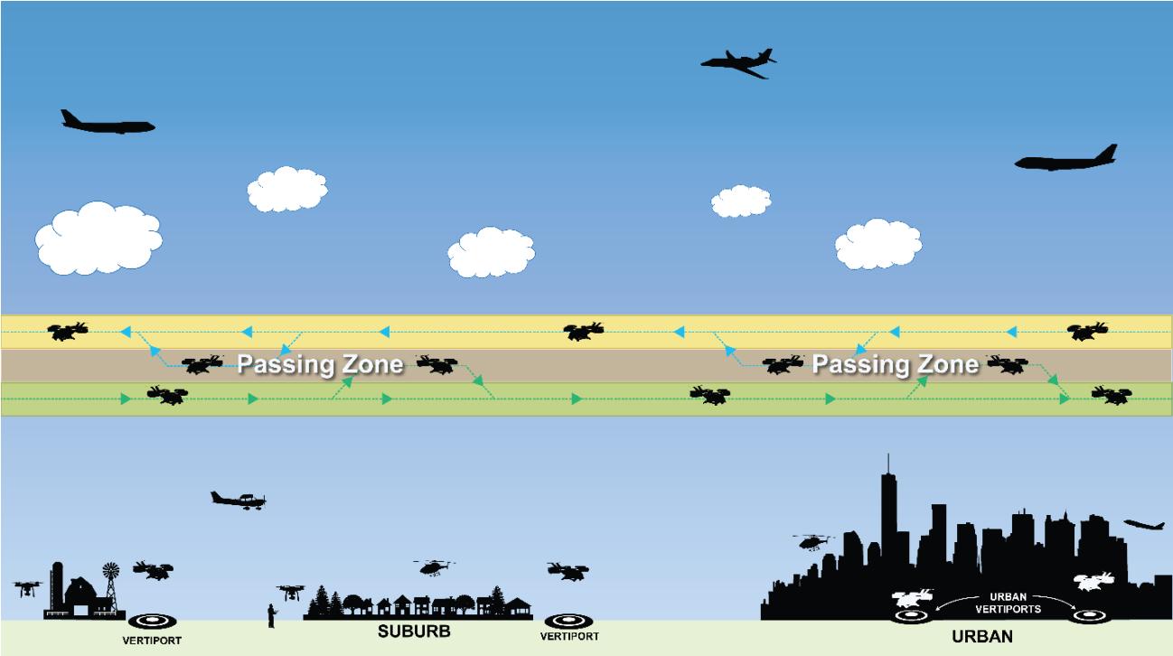
Figure 5: Use of a Vertical Common Passing Zone
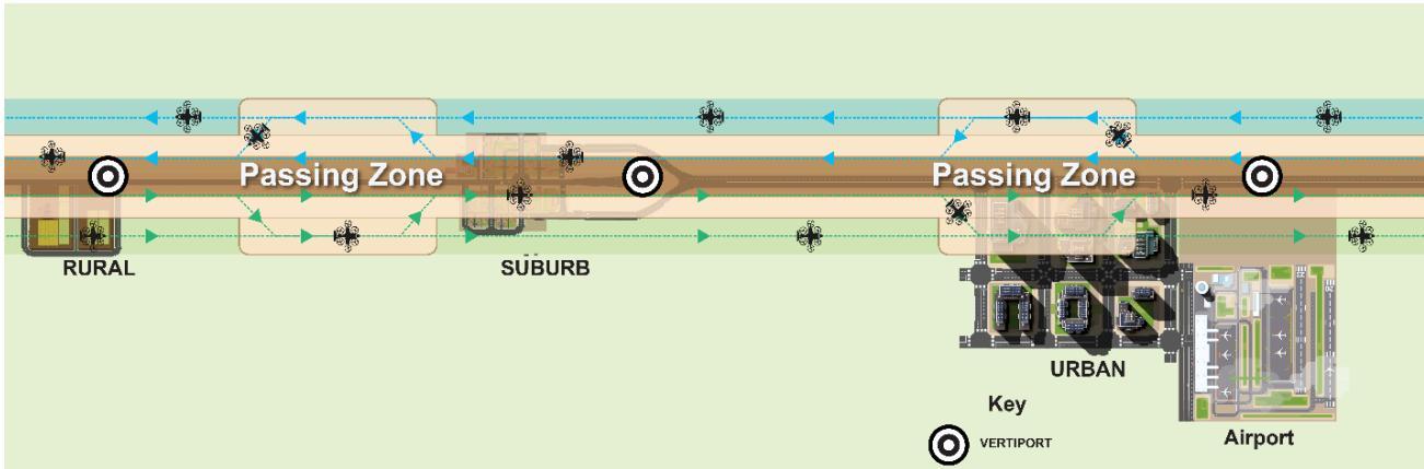
Figure 6: Use of Lateral Passing Zones
As the operational tempo and breadth of UAM aircraft physical performance (e.g., speed) continue to increase, Figure 7 depicts a notional internal UAM Corridor structure comprised of multiple “tracks.” The tracks reflect additional internal structure, which may also require increased performance requirements that support an increased operational tempo within the same UAM Corridor.
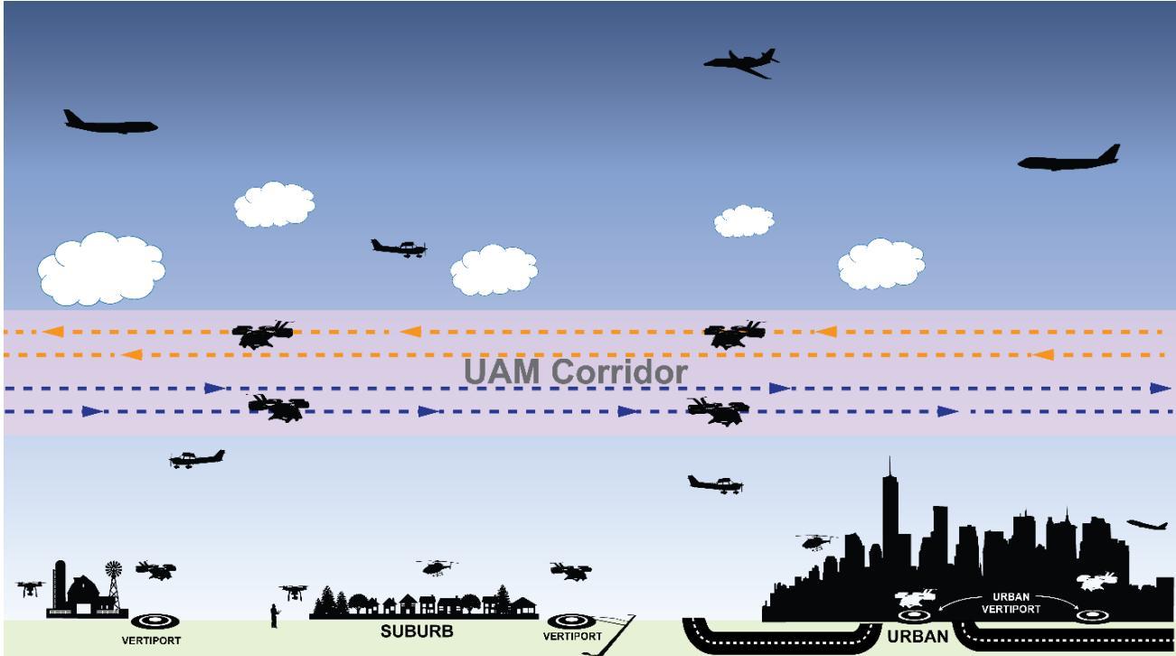
Figure 7: UAM Corridor with Multiple Tracks
## 4.5 Weather and Obstacles Within the UAM Environment
PSUs or SDSPs support the UAM operator by supplying weather, terrain, and obstacle clearance data specific to the UAM operation. This data is accessed in the UAM Operational Intent planning phase to ensure strategic management of a UAM operation and updated in-flight, as appropriate. UAM operators monitor weather and winds prior to and throughout flight. If aircraft performance is inadequate to maintain required separation within the UAM Corridor, UAM operators are responsible to take appropriate action to ensure separation is maintained (e.g., do not take off, exit the UAM Corridor, operate per appropriate airspace rules).
## 4.6 Constraint Information and Advisories
UAM operators are responsible for identifying operational conditions or flight hazards that may affect an operation. This information is collected and assessed both prior to and during flight to ensure the safe conduct of the flight. PSUs support this UAM operator responsibility by supplying information and advisories including, but not limited to:
• Other airborne traffic including operations within and crossing UAM Corridors.
• Weather and winds.
Other hazards pertinent to low-altitude flight (e.g., obstacles such as a crane or powerline Notice to Air Missions (NOTAM), bird activity, local restrictions).
SAA status.
• UAM Corridor availability.
The sharing of projected demand and available capacity information between ATS and federated service network supports the applicable flow management function (e.g., TFM, CFM). Constraints may be shared from one environment to be complied with by the other, consistent with applicable procedures, COPs, and regulations.
## 5 Notional Architecture
Within the UAM cooperative management environment, the FAA would maintain regulatory and operational authority for airspace and traffic operations. UAM operations may be organized, coordinated, and managed by a federated set of actors through a distributed network that leverages interoperable information systems. Figure 8 depicts a notional architecture of the UAM actors and contextual relationships and information flows. This architecture is based on patterns established within the UTM architecture described in the UTM ConOps [2] and is consistent with the architecture described in the ETM ConOps [3].
The federated service network, comprised of individual PSUs operating as a collective, lies at the center of the UAM notional architecture and exchanges data with UAM operators, USSs, SDSPs, the FAA, and public interest stakeholders. PSUs receive supplemental data supporting UAM operation management from the SDSPs and provide relevant UAM operational data to the public. PSUs communicate and coordinate via the federated service network. This allows other UAM stakeholders (e.g., UAM operators, ATC, law enforcement) connected to a PSU to access data shared across the federated service network.
PSUs and USSs may exchange operational information about UAM and UTM operations in airspace under 400 feet where there is a potential need for cooperative separation (e.g., vertiports). Notionally, a USS can expand their service offerings to become a PSU and vice versa. Combined service providers may support operations in both the UAM and UTM environments. The architecture depicts the connectivity of the federated service network to USSs for information exchange while retaining a UAM-centric architectural view.
Vertiports exchange information with the federated service network to facilitate the communication of situational awareness and resourcing information to UAM operators. The PSUs make the aggregate vertiport information available for the operator to be aware of capacity and situational constraints present at the time of respective departure and arrival time. PSUs could potentially provide additional services with this information (e.g., suggested alternate vertiports, suggested alternate departure/arrival times).
The vertical dashed line in Figure 8 represents the demarcation between the FAA and industry responsibilities for the infrastructure, services, and entities that interact as part of UAM. The FAA-Industry Data Exchange Protocol provides an interface for the FAA to request UAM operational data on demand and send FAA information to the federated service network for distribution to UAM operators, PICs, UAM aircraft, and public interest stakeholders through the Service Security Gateway.
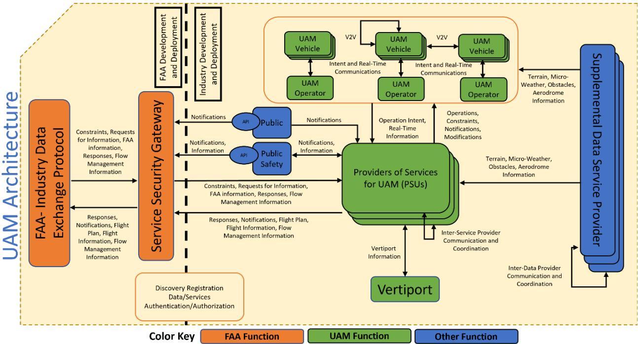
Figure 8: Notional UAM Architecture
## 5.1 Supporting Services
UAM services that may be provided by PSUs and SDSPs are intended to be modular and discrete, allowing for increased flexibility in the design and implementation of new services. This modular approach would allow the FAA to provide tailored oversight of UAM operations and allows PSUs and SDSPs to provide focused services consistent with a business model and subscriber needs. Similar to UTM, UAM services may be characterized in one of the following ways.
1. Services that are required to be used by UAM operators due to FAA regulation or for a direct connection to FAA systems. These services must be qualified and approved by the FAA.
2. Services that may be used by a UAM operator to meet all or part of an FAA regulation. These services must meet an acceptable means of compliance and may be individually qualified and approved by the FAA.
3. Services that provide value-added assistance to a UAM operator but are not used for FAA regulatory compliance. These services may meet an industry standard but may not be qualified or approved by the FAA.
## 6 UAM Scenarios
This section provides high-level scenarios reflecting two operations. The first is conducted from departure to arrival within a UAM Corridor. The second operation departs a vertiport in the current Class B service environment (ATS), enters a UAM Corridor for a portion of the flight, exits back into Class B (ATS) and arrives at the vertiport. These scenarios further explore the UAM concept and each steps through phases of the flight’s operation, illustrating the operational and architectural information from Sections 4 and 5.
The scenarios demonstrate a subset of UAM operations and interactions during specific nominal operations. A nominal UAM operation is a single UAM operation that executes in accordance with the established performances, rules, policies, and procedures.
## 6.1 Nominal UAM Operation Completed Within a UAM Corridor
## 6.1.1 Planning Phase
Planning of this operation starts with the UAM operator receiving a request from an individual flight between Vertiport 1 and Vertiport 2.
The UAM operator obtains current conditions from the information provided by the subscribed PSU and relevant SDSP service. After determining that the current conditions are acceptable for the operation, the UAM operator submits desired UAM Operational Intent information (e.g., identifying information, vertiport locations, route of flight via UAM Corridor(s), desired time of operation) to the subscribed PSU.
The PSU, through the federated service network:
1. Evaluates the desired UAM Operational Intent against other operations that may cause a strategic conflict.
2. Evaluates UAM Operational Intent against known airspace constraints (e.g., FAA originating constraints, local restrictions).
3. Identifies availability of UAM Corridors and UAM vertiport resources.
Because there are no conflicting operations, airspace restrictions (e.g., Temporary Flight Restrictions [TFRs]), or vertiport resource limitations, the UAM operator’s desired UAM Operational Intent is considered strategically deconflicted and confirmed. The PSU notifies the UAM operator and provides the UAM Operational Intent to the federated service network.
The UAM operator considers possible modifications to the Operational Intent in the event of an off-nominal situation. The airspace classes and ATC facilities with jurisdiction for the airspaces that border the UAM Corridor(s) for the operation are identified. These prepare the PIC in case a contingency operation is required.
Most of the planning actions and information exchanges between the UAM operator and PSU are automated and expected to take very little time from the initial customer request to the confirmed UAM Operational Intent.
## 6.1.2 In-Flight Phases
Throughout all phases of flight, the UAM aircraft identification and location information are available to the UAM operator and subscribed PSU. The PIC and UAM operator monitor aircraft
performance to ensure nominal operation status is maintained. The PSU monitors Operational Intent conformance.
## 6.1.2.1 Departure Phase
The PIC departs from Vertiport 1 within the departure compliance window and enters the UAM Corridor.
## 6.1.2.2 En Route Phase
The PIC navigates along the UAM Corridor per the UAM Operational Intent. The UAM aircraft completes the en route portion of the flight per the UAM Operational Intent and approaches the arrival vertiport within the compliance window of the arrival time.
## 6.1.2.3 Arrival Phase
As the UAM aircraft approaches Vertiport 2, the PIC, UAM operator, PSU, and UAM vertiport confirm the landing pad is still available per the UAM Operational Intent. The PIC navigates to the allocated vertiport pad and lands the aircraft.
## 6.1.3 Post-Operations Phase
The UAM operator and PIC provide mission complete indication to the PSU. The PSU archives required UAM operational data per regulation.
## 6.2 Nominal UAM Operation Across Service Environments
This scenario describes a situation where a UAM operator plans a flight that departs from Vertiport 3, located in Class B airspace, and arrives at Vertiport 4, within Class B airspace, after using a UAM Corridor for transit. The operator enters and exits the UAM service environment through CEPs. Confirmed UAM Operational Intent is required for participation within the UAM environment. The UAM operators utilize a PSU who provides flight plan filing services.
## 6.2.1 Planning Phase
Planning of this operation starts with the UAM operator receiving a request from an individual customer for a flight between Vertiport 3 and Vertiport 4. The UAM operator obtains current conditions and vertiport availability from their subscribed PSU as well as relevant SDSP services (e.g., environment, situational awareness, strategic operational demand, supplemental data).
After determining the current conditions are acceptable for the operation, the UAM operator provides the necessary information to the PSU. In this case, the operation will use a UAM Corridor that traverses Class B airspace and operate within the Class B airspace to/from the UAM Corridor. In recognition of the cross-service environment operation, the operator’s information for the portion of the flight planned for the UAM Corridor includes the desired UAM Operational Intent information (e.g., identifying information, vertiport locations, route of flight via UAM Corridor(s), CEP locations, desired time of operation). As the operation, upon departure, will operate in Class B airspace, the operator also provides the PSU the required flight plan information for the ATS environment (e.g., flight ID, type of aircraft, route to CEP from departure vertiport, route from CEP to arrival vertiport). The PSU uses the flight plan information to coordinate with TFM and CFM services to secure clearance times and slot reservations for CEPs within the CA.
The subscribed PSU transmits the applicable information (e.g., flight information, flight plan) to the relevant ATS/xTM data exchange network as required by relevant regulations and COPs. The PSU receives information (e.g., ATC/TFM responses, notices, constraints) from the ATS data exchange portal for the UAM operator to use for situational awareness or to modify the planned intent/flight plan.
The PSU, through the federated service network:
1. Evaluates the desired UAM Operational Intent for other operations that may cause a strategic conflict.
2. Evaluates the UAM Operational Intent against known airspace constraints (e.g., FAA originating constraints, local restrictions).
3. Identifies availability of the UAM Corridor and UAM vertiport resources.
4. Receives any applicable flow management initiatives or constraints.
5. Files the flight plan from Vertiport 3 to Vertiport 4 through the UAM Corridor.
If there are no conflicting operations, airspace restrictions (e.g., TFRs), applicable flow management constraints (i.e., CFM and TFM), or vertiport resource limitations, the UAM operator’s desired UAM Operational Intent is considered strategically deconflicted and confirmed. The PSU notifies the UAM operator and provides the final UAM Operational Intent to the federated service network and flight plan information to the ATS exchange (e.g., Expect Departure Clearance Time [EDCT]).
Most of the planning actions and information exchanges (e.g., intent, flight plan filing) across the federated service network, ATS (i.e., ATC and TFM), operator, and PSU are automated and expected to take very little time from the initial customer request to the confirmed UAM Operational Intent and flight plan filing.
## 6.2.2 In-Flight Phases
Throughout all phases of flight (e.g., departure, en route, arrival) for a UAM operation, the UAM aircraft identification and location information are available to the UAM operator, ATC facility, and subscribed PSU. The PIC and UAM operator monitor aircraft performance to identify an offnominal state. The PSU monitors operational conformance to the confirmed UAM Operational Intents. Data exchange between CFM and TFM are monitored for accuracy and relayed to ATC and the PSU.
## 6.2.2.1 Departure Phase
Prior to departure, the PIC establishes two-way communication with the appropriate ATC facility to open the submitted flight plan that was submitted by the PSU. The PIC departs from Vertiport 3 within the departure compliance window, notifies the PSU (via automated departure acquisition), and enters Class B airspace. The UAM PIC monitors applicable ATC frequencies and complies with instructions while in Class B airspace. The UAM aircraft transitions into the UAM Corridor through the CEP submitted through the Operational Intent.
## 6.2.2.2 En Route Phase
The PIC navigates along the UAM Corridor per the confirmed UAM Operational Intent. The PIC deconflicts from other aircraft within the UAM Corridor with possible support from the UAM aircraft equipage or PSU services (e.g., flight data from active operations in the UAM Corridor). Flight status is monitored by CFM to TFM and updated as necessary within the system. The UAM aircraft completes the en route portion of the flight per the UAM Operational Intent and approaches the CEP within the compliance window of the arrival time.
## 6.2.2.3 Arrival Phase
Prior to arriving at the submitted CEP to exit the UAM Corridor into Class B airspace, the data exchange (e.g., handoff) is activated to ATC and frequency change is conducted. The UAM PIC establishes two-way communication and positive clearance with the appropriate ATC facility. The UAM aircraft enters Class B airspace through the CEP per ATC instruction.
As the UAM aircraft approaches Vertiport 4, the PIC, UAM operator, PSU, and UAM vertiport confirm the landing pad is still available per the UAM Operational Intent. The PIC navigates to the allocated vertiport pad and lands the aircraft.
## 6.2.3 Post-Operations Phase
The UAM operator/PIC provides mission completion indication to the PSU and the ATC facility.
The PSU archives required UAM operational data.
## 7 UAM Evolution
The UAM ConOps 2.0 reflects FAA efforts, in collaboration with NASA, industry, and other stakeholders, to advance UAM. It begins with the introduction of low-complexity, low-operational tempo operations leveraging the current regulatory framework (e.g., VFR, IFR) and building toward higher operational tempo with the institution of UAM airspace structures (i.e., UAM Corridors) where and when operationally advantageous, using a performance-based construct.
As operations occur and experience is gained, the concept may mature and evolve as the FAA continues to engage stakeholders for their perspectives on new technologies, techniques, and automation, both ground-based and airborne, to identify those most capable of addressing the evolving challenges and opportunities. This evolutionary approach to UAM could provide advantages. By initially supporting lower complexity operations, implementation can be streamlined to the environment using current capabilities that meet performance requirements and do not require full-scale regulatory and operational infrastructure changes. Incremental changes to the regulatory framework, “hard” infrastructure (e.g., systems and vertiports), and “soft” infrastructure (e.g., processes and procedures) could help support the UAM operational demand and complexity as they increase in concert with other cooperative environments, such as UTM and AAM. These incremental changes may also support the progression of the existing ATS system, maintaining fair and equitable access to airspace across the full airspace user community.
## Appendix A References
[1] International Civil Aviation Organization (ICAO), Document 9854, Global Air Traffic Management Operational Concept (GATMOC), First Edition, 2005.
[2] FAA, Unmanned Aircraft System (UAS) Traffic Management (UTM) Concept of Operations (ConOps) Version 2.0. 2020.
[3] FAA, Upper Class E Traffic Management (ETM) Concept of Operations (ConOps) Version 1.0. 2020.
## Appendix B Acronyms
All acronyms used throughout the document are provided in Table 1.
Table 1: Acronyms
| Acronym | Definition |
| AAM | Advanced Air Mobility |
| AFR | Automated Flight Rule |
| ATC | Air Traffic Control |
| ATS | Air Traffic Services |
| CA | Cooperative Area |
| CBR | Community Business Rule |
| CEP | Corridor Entry/Exit Point |
| CFM | Cooperative Flow Management |
| CNS | Communication, Navigation, and Surveillance |
| COP | Cooperative Operating Practice |
| ConOps | Concept of Operations |
| DCB | Demand-Capacity Balancing |
| DEP | Distributed Electric Propulsion |
| DOT | Department of Transportation |
| EDCT | Expect Departure Clearance Time |
| ETM | Upper Class E Traffic Management |
| eVTOL | Electric Vertical Takeoff and Landing |
| FAA | Federal Aviation Administration |
| G/G | Ground-to-Ground |
| HOTL | Human-on-the-Loop |
| HOVTL | Human-Over-the-Loop |
| HWTL | Human-Within-the-Loop |
| IFR | Instrument Flight Rules |
| IMC | Instrument Meteorological Conditions |
| LOA | Letter of Agreement |
| MRO | Maintenance, Repair, and Overhaul |
| NAS | National Airspace System |
| NASA | National Aeronautics and Space Administration |
| NOTAM | Notice to Air Missions |
| PIC | Pilot in Command |
| PSU | Provider of Services for UAM |
| RPIC | Remote Pilot in Command |
| SAA | Special Activity Airspace |
| SDSP | Supplemental Data Service Provider |
| TFM | Traffic Flow Management |
| TFR | Temporary Flight Restriction |
| UAM | Urban Air Mobility |
| UAS | Unmanned Aircraft Systems |
| USS | UAS Service Supplier |
| UTM | UAS Traffic Management |
| V2V | Vehicle-to-Vehicle |
| VFR | Visual Flight Rules |
| VMC | Visual Meteorological Conditions |
| VTOL | Vertical Takeoff and Landing |
| xTM | Extensible Traffic Management |
## Appendix C Glossary
Table 2 provides a glossary of UAM terms used throughout this ConOps. These terms are in addition to those defined in Section 1.4, which provides terms key to establishing the context of the UAM concept.
Table 2: Glossary
| Acronym | DefinitionThe terms "advanced air mobility” and “AAM'"' mean atransportation system that transports people and property by airbetween two points in the United States using aircraft with advancedtechnologies, including electric aircraft or electric vertical take-offand landing aircraft, in both controlled and uncontrolled airspace. |
| Advanced AirMobility (AAM) |
| Conflict | Any situation involving aircraft and hazards in which the applicableseparation minima may be compromised [1]. |
| Constraint | An impact to the capacity or use of a resource preferred by anoperator, defined with time and geographically specified airspaceinformation. A constraint may restrict access to airspace foroperations or may be advisory in nature. |
| CooperativeSeparation | Separation based on shared flight intent and data exchanges betweenoperators, stakeholders, and service providers. Cooperativeseparation is supported by defined COPs as well as applicable rules,regulations, and policies. |
| Demand-CapacityBalancing (DCB) | Strategic evaluation of system-wide traffic flows and aerodromecapacities to allow airspace users to determine when, where, and howthey operate, while mitigating conflicting needs for airspace andaerodrome capacity. This collaborative process allows for theefficient management of air traffic flow through the use of information on system-wide air traffic flows, weather, and assets [1]. |
| Human-on-the-Loop(HOTL) | Human supervisory control of the automation (i.e., systems) where the human actively monitors the systems and can take full controlwhen required or desired. |
| Human-Over-the-Loop (HOVTL) | Human informed, or engaged, by the automation (i.e., systems) to take actions. Human passively monitors the systems and is informedby automation if, and what, action is required. Human is engaged bythe automation either for exceptions that are not reconcilable or aspart of rule set escalation. |
| Human-Within-the-Loop (HWTL) | Human is always in direct control of the automation (systems). |
| Acronym | Definition |
| Operational Intent | Also referred to as operation intent, the future operational positioninformation, consisting of spatial and temporal elements, that isexchanged between xTM operators to support cooperative trafficmanagement. |
| Operational Tempo | The density, frequency, and complexity of operations. |
| Provider of Servicesfor UAM (PSU) | An entity that assists UAM operators with meeting UAM operationalrequirements to enable safe and efficient use of UAM Corridors andvertiports. This service provider shares operational data withstakeholders and confirms flight intent. |
| StrategicDeconfliction | The process of arranging, negotiating, and prioritizing OperationalIntent (e.g., volumes, routes, trajectories, time assignments) ofaircraft to minimize the likelihood of airborne conflicts betweenoperations. |
| Tactical Deconfliction | The process of executing one or more actions to avoid an airborneconflict in a timely manner when strategic deconfliction has failed orwas not executed. |
| UAS TrafficManagement (UTM) | The manner in which the FAA will support operations for UASoperating in low-altitude airspace. |
# FAA AAM Implementation Plan (I28)

## Advanced Air Mobility (AAM) Implementation Plan
Near-term (Innovate28) Focus with an Eye on the Future of AAM Version 1.0 / July 2023

PAGE INTENTIONALLY BLANK
## Table of Contents
1 Advanced Air Mobility... . 1
1.1 AAM Definition .. . 1
1.2 AAM Integration into the National Airspace System... .. 1
1.3 Stakeholder Collaboration . .. 2
2 Introduction to Innovate28 .... ... 5
3 Implementation Plan Overview .... .. 6
4 Innovate28 Key Site Operations.. .. 7
4.1 AAM Aircraft ....... ... 7
4.2 AAM Operations..... ..... 8
4.3 I28 Scenario.... . 13
5 Innovate28 Workstreams.. . 15
5.1 Certification ..... ... 15
5.2 Operational Suitability .. . 15
5.2.1 Operations Certification . . 16
5.2.2 Aircraft Certification... . 18
5.3 Airspace and Air Traffic Management.. . 20
5.4 Infrastructure.... . 22
5.4.1 Existing Infrastructure . . 22
5.4.2 New Infrastructure... .. 23
5.4.3 Vertiport-Related Research . .. 23
5.4.4 Vertiport Standards and Oversight. . 24
5.5 Environment... .. 25
5.6 Hazardous Materials Safety ... . 26
5.7 Community Engagement... . 27
6 Innovate28 Integrated Schedule .... . 28
7 AAM Evolution Framework.... . 31
## List of Figures
Figure 1. Integrated Master Schedule Version 1.0......... .. 29
## List of Tables
Table 1. Detailed List of Activities in the Integrated Master Schedule Version 1.0 30
Table 2. AAM Coordination Areas... .. 32
Table 3. AAM Maturity Levels.. . 33
## 1 Advanced Air Mobility
Transportation is constantly evolving, and each step forward yields new opportunities that fundamentally change how people and goods are being transported. A new era of aviation once only portrayed in movies or science fiction is taking off. Advanced Air Mobility (AAM) is an emerging aviation ecosystem that leverages new aircraft and an array of innovative technologies to provide the opportunity for more efficient, more sustainable, and more equitable options for transportation.

## 1.1 AAM Definition
As defined in the AAM Coordination and Leadership Act (P.L. 117-203, 136 Stat. 2227), October 17, 2022, “AAM is a transportation system that moves people and property by air between two points in the United States (U.S.) using aircraft with advanced technologies, including electric aircraft, or electric vertical takeoff and landing (eVTOL) aircraft, in both controlled and uncontrolled airspace.” For purposes of this Implementation Plan, however, the scope of AAM is limited to those engaging in passenger-carrying or cargo operations with a pilot on board.
## 1.2 AAM Integration into the National Airspace System
The Federal Aviation Administration (FAA) has a long, successful history of bringing new technologies safely into aviation. The agency’s role in integrating AAM into the National Airspace System (NAS) is to ensure this new generation of aircraft maintains the highest level of operational safety that defines commercial aviation today. The FAA’s top priority and statutory responsibility are to ensure the safety of the traveling public. The agency is looking at every necessary aspect to support AAM flights: the aircraft itself, the framework for operations, access to the airspace, operator training, infrastructure development, environmental impacts, and community engagement.
As these aircraft are being developed, the FAA will amend, as appropriate, operational rules and pilot training requirements. Longer term, the agency will develop permanent regulations to safely enable powered lift operations and pilot training and certification.

## The FAA is implementing a crawl-walk-run
methodology that recognizes early opportunities to support Entry into Service (EIS) operations through existing services and infrastructure with minimal changes. The agency is doing this while developing a path to implementation of more advanced concepts and capabilities to support increasing scale and automation of AAM operations, as well as integration with other types of aircraft operating in the NAS.
To address the development of a near-term ecosystem, the FAA created Innovate28 (I28), a joint government and industry initiative that will culminate in integrated AAM operations at one or more key site locations by the 2028 timeframe. The FAA also recognizes and has begun executing the collaborative actions needed to mature AAM concepts, operations, and regulatory frameworks beyond initial operations and into the mid-term and mature state phases (see Section 7). This Implementation Plan shows how the agency expects all these pieces to come together to allow the industry to scale safely.
## 1.3 Stakeholder Collaboration
Operationalizing AAM in the NAS and establishing timelines from EIS to operations at scale requires collaboration with, and commitments by, many stakeholders to ensure safe, efficient, and equitable operations, including:
## Federal Aviation Administration
From a federal level, the FAA has sole and exclusive authority over all aviation safety aspects of AAM integration, including operating rules, aircraft certification, and pilot certification. The agency provides a leadership role in identifying and integrating the responsibilities of all the key actors and stakeholders. The FAA develops and processes all certification, policy and procedures, rulemaking, and regulatory activities to ensure safety of flight, and strives to ensure that industry (including original equipment manufacturers (OEMs), aircraft operators, and vertiport operators) and local, state, and tribal governments can accommodate AAM operations and plan accordingly.
In support of I28, the FAA established internal workstreams, called iTeams. These teams are dedicated to addressing major focus areas for AAM integration, including Certification, Airspace and Air Traffic Management, Infrastructure, Environment, Hazardous Materials Safety, and Community Engagement, to ensure a coordinated approach for I28 operations.
## Other Government Agencies
The FAA is leveraging existing programs and research conducted by other government agencies to integrate AAM more rapidly into the NAS, including the National Aeronautics and Space Administration (NASA), U.S. Department of Transportation (DOT), Department of Defense, and others. For example, through the FAA’s extensive AAM-focused partnership with NASA’s AAM Program and the National Campaign and collaboration with the U.S. Air Force AFWERX Prime programs, the FAA is able to leverage the research, data, and testing experience in the shared mission to safely integrate AAM aircraft.
In addition to collaboration at the federal level, the FAA is engaging with local, state, tribal, and territorial governments that have vested interests in making decisions to ensure safe and successful AAM operations from local and regional planning, power infrastructure, intermodal transportation, and community perspectives. These entities will likely be responsible for the coordination, logistics, zoning, licensing of infrastructure, and the community engagement necessary to support AAM operations.
## Inter-Agency Working Groups
The FAA participates in several inter-agency AAM groups, including the DOT AAM Interagency Working Group, which was established by the AAM Coordination and Leadership Act. Much like the FAA iTeams’ structure, the DOT AAM Interagency Working Group is coordinating efforts related to safety, operations, infrastructure, physical security and cybersecurity, and federal investment necessary for maturation of the AAM ecosystem in the U.S. They are focused on ensuring cohesive and consistent Executive Branch-wide policy through a collaborative and proactive approach that supports the FAA’s integration of AAM into the NAS.
The FAA also participates in the newly-formed International Civil Aviation Organization (ICAO) AAM Study Group. The 41st ICAO Assembly recognized that the rapidly evolving AAM ecosystem requires a globally harmonized operational and regulatory framework and guidance. ICAO provides the forum for 26 international stakeholders to develop a holistic vision and framework to achieve global harmonization and interoperability of AAM implementation, allowing all countries to benefit from the AAM operations. The FAA and other government agencies participate in all relevant ICAO technical panels that will ultimately work on international standards and recommended practices for AAM as the specific work is forwarded for their action from the AAM Study Group.
## AAM Operators and Manufacturers
Companies developing or operating AAM aircraft are key stakeholders in the integration process. These companies will need to work with government agencies to bring forward the use cases and locations of interest, obtain necessary certifications and approvals, and ensure that their aircraft and operations meet safety and regulatory requirements. They will also need to consider the environmental impacts of their aircraft and operations, engage with relevant communities, and minimize environmental and other impacts on communities.
## Infrastructure Providers
Any time new transportation is introduced, communities must plan for the integration of those operations either within existing infrastructure or through the development of new facilities. Companies that provide charging stations, vertiports, and other infrastructure necessary for AAM operations will also play a role in integration. Providers of private infrastructure that do not require FAA approval will, in particular, need to engage with relevant communities, minimize environmental and other impacts on communities, and foster community support.
## Communities and the Public
As AAM aircraft begin to operate in urban areas, communities and the general public will be affected by these new technologies, capabilities, and services. Community involvement is the process of engaging in dialogue and collaboration with communities affected by FAA actions. This process supplements the public involvement activities required under other laws or requirements. Public engagement and education through involvement of all stakeholders will be necessary to ensure that communities understand the benefits and impacts of AAM operations, and to address any concerns they may have. The AAM industry offers the prospects of convenient alternatives to traditional transportation, as well as increased access to air transportation. However, for this emerging industry to reach its fullest potential, it must gain the support of the general public. The FAA encourages communities to get involved now in these early phases, and to stay engaged.
## 2 Introduction to Innovate28

On May 3, 2023, the FAA released Version 2.0 of the Urban Air Mobility (UAM) Concept of Operations (ConOps) that describes the technical roadmap for enabling UAM, which is an urban-focused subset of AAM, from the near-term to far-term. The focus of this Implementation Plan, Version 1.0, is to document the work required to enable initial AAM operations in a variety of operational settings or “key sites” in the near-term.
## Initial Integration of AAM Operations at One or More Key Sites
Innovate28 (I28) is an FAA initiative that will culminate in integrated AAM operations with OEMs and/or operators flying between multiple origins and destinations at one or more locations in the U.S. by 2028. I28 marks one milestone on the AAM evolutionary continuum and the path to full integration and operations at scale across the NAS. I28 will leverage public-private partnerships to identify key locations and use cases of interest to AAM industry stakeholders while promoting an all-hands-on deck approach to ensure the necessary steps are taken to enable these operations. Leveraging lessons learned from OEMs and/or operators conducting individual EIS building block operations, I28 operations are expected to be larger in scale than initial EIS operations. I28 is intended to result in “leave behind” processes, infrastructure, procedures, and local knowledge at the key site(s). Additionally, the collective experience gained through the I28 initiative is expected to support expanded operations in other areas of the country.
## Repeatable Implementation Methodology
The I28 implementation approach includes documenting steps and protocols and collecting data over the course of the effort to develop a repeatable methodology, including processes, procedures, and mechanisms, for expanding AAM operations to other locations across the NAS. This methodology will be used as a guide for future sites to collaborate with the FAA and other stakeholders to streamline implementation of AAM solutions. The FAA will also leverage the I28 efforts, as well as the EIS building blocks, in its ongoing work to evolve and advance AAM into the future.
## 3 Implementation Plan Overview
This AAM Implementation Plan is a living document that will guide implementation efforts and mature as the FAA works with stakeholders to refine and execute AAM implementation strategies. It will be updated periodically to reflect the continued plans and progress with AAM integration, roadmaps, and schedules for I28 and beyond as work continues to advance towards the mature state vision of AAM operations across the NAS.
Version 1.0 provides details for the near-term I28 initiative, which will enable a repeatable AAM ecosystem at key locations based on information known to date. The evolution of AAM beyond I28 is also previewed. Version 1.0 specifically addresses the following:

## • I28 Key Site Operations
o Description of the operating environment in 2028 based on assumptions and expectations of AAM aircraft and operations, including a scenario thread for a generic key site location
o Overarching framework that FAA stakeholders can use to identify and work through key challenge areas, executing to a common vision
## I28 Workstreams
o Holistic approach to the required efforts, both internal and external to the FAA, needed to meet I28 goals (presented in Section 2)
O Descriptions of work completed to date and gaps to be addressed in Certification, Airspace and Air Traffic Management, Infrastructure, Environment, Hazardous Materials Safety, and Community Engagement
## I28 Integrated Master Schedule
o Detailed schedule across workstream focus areas that supports I28 operations and leave behind processes
o Tool for tracking the milestones of internal and external stakeholders (e.g., tribal/state/local government, and industry) who manage their own activities relevant to implementation at specific site(s)
## • AAM Evolution Framework
o High-level view of the evolution of AAM operations and an associated framework for the continued development and commitments that are needed to advance AAM integration in the NAS
## 4 Innovate28 Key Site Operations
The I28 initiative envisions a near-term AAM operational ecosystem that has advanced from EIS at various locations to substantive presence at locations of interest. Since AAM aircraft are currently undergoing or are being planned to undergo the certification process, and specific operational needs are still being defined, it is necessary to make assumptions as to how the AAM industry will operate and what the supporting capabilities will be in 2028. The I28 key site operations presented here are based on industry and FAA projections on the state of technology development, air and ground supporting infrastructure and services, and other capabilities. These assumptions will continue to be updated in future versions of this document as the industry advances and regulations are developed.
The following addresses the assumptions and expectations about AAM aircraft with respect to certification and operating characteristics. I28 AAM operations are then described in the context of the operating environment, including flight operations, airspace usage and route structure, air traffic control (ATC) services, and infrastructure. A scenario thread is also presented for an I28 AAM operation.
## 4.1 AAM Aircraft
For I28, AAM aircraft will be authorized for piloted operations and will transport passengers and/or cargo within the limits of the aircraft and certification regulations. The aircraft are expected to range in size from single passenger to larger occupancy shuttles, and employ new means of propulsion (e.g., electric motors, hydrogen fuel, hybrid designs). Many are capable of vertical takeoff and landing (VTOL) or short takeoff and landing (STOL) operations and quickly transition to fixed-wing operation after takeoff. It is assumed wake characteristics will be known, including the impacts of wake from other aircraft on AAM
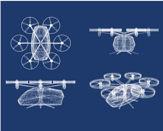
aircraft and an AAM aircraft’s own wake generation.
AAM aircraft are expected to be type certificated as special class under 14 Code of Federal Regulations (CFR) § 21.17(b). Because these aircraft have novel airframes and powerplants, the FAA is using many of the performance-based regulations in 14 CFR part 23, Airworthiness Standards: Normal Category Airplanes, for the certification basis. AAM commercial operators are expected to be certified to operate under 14 CFR part 135, Operating Requirements: Commuter and on Demand Operations and Rules Governing Persons on Board Such Aircraft. Pilots of powered lift aircraft are expected to be rated (type rated as required) for each powered lift aircraft they fly, and they will be required to meet updated qualification requirements for operating under part 135.
AAM aircraft are expected to operate under part 135, including seeking FAA approval for the carriage of dangerous goods and hazardous materials, consistent with the aircraft’s type certificated operating weight to include passenger carriage or cargo capability and their frequency of
operations. These operations must be part of the operator’s FAA approved Dangerous Goods program and further authorized within the operator’s Operations Specifications.
## 4.2 AAM Operations
The descriptions of I28 AAM operations in this section are agnostic to location. As key sites are identified, site-specific airspace and air traffic management (ATM) solutions will be developed for operations within defined geographical areas based on AAM operator use cases.
## Airspace Usage and Route Structure
AAM operators are expected to comply with existing communication, navigation, and surveillance (CNS) requirements for the airspace in which they will operate. For I28, the expectation is that the aircraft will operate from the surface to 4000’ above ground level in urban and metropolitan areas, and in relatively close proximity to or directly on airports. This means that AAM aircraft will operate predominately in or around Class B and C airspace.
To operate within Class B airspace, pilots must receive ATC clearance, and aircraft are required to be equipped with an operating two-way radio, Automatic Dependent Surveillance – Broadcast (ADS-B) Out, suitable navigation capability, and an operable transponder with altitude reporting capability. Initial AAM aircraft operations are generally expected to operate in compliance with Visual Flight Rules (VFR) weather minima in visual meteorological conditions (VMC).
VFR aircraft operating within Class B airspace receive separation services from ATC. VFR aircraft may obtain an ATC clearance to transit Class B airspace, if needed, however, the FAA encourages VFR pilots to operate above or below, or transit Class B airspace using established VFR corridors. To operate within Class C airspace, pilots must initiate twoway radio communications prior to entry and maintain communications while in the airspace. They must also be equipped with a two-way radio and an operable transponder with altitude reporting capability.
The addition of AAM operations will add to the already busy traffic levels of Class B and C airspace. In cases where existing VFR procedures do not meet the needs of air traffic facilities or AAM operators, special agreements or coordination may need to occur to accommodate the increase in traffic levels. Ideally, agreements made at the local level will reduce ATC workload.
Charted routes will be the primary routing structure used by AAM aircraft. This approach enables the FAA to develop routes that accommodate AAM operator needs while leveraging the existing design and charting processes. The development of airspace route structures for I28 operations will consider design standards based on 14 CFR parts 135 and 91, General Operating and Flight Rules, local procedures, terrain, and traffic flows. Pilot adherence to charted I28 routes and the recommended
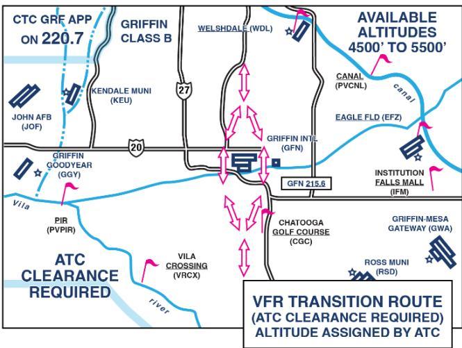
altitudes or flight ceilings associated with them are voluntary. However, ATC may assign charted routes and altitudes where pilot compliance is required, provided such procedures are called for in specific FAA-operator Letters of Agreement (LOAs), or are necessitated by traffic density and/or safety considerations. ATC may also restrict operations within designated operating zones when certain criteria are met, and as requested by the appropriate authorities. Noise and other environmental considerations are accounted for in the airspace design. Changes to airspace design and/or new routes will likely require the FAA to conduct environmental review and community outreach.
I28 AAM routes will be designed for use in VFR conditions only, and where possible, use existing or modified low altitude VFR routes and constructs. While these routing constructs do not inherently provide separation or segregation of participating AAM traffic, they are developed to assist pilots in avoiding major controlled traffic flows. The routes1 may include:
VFR flyways - General flight paths not defined as a specific course, for use by pilots in planning flights into, out of, through or near complex terminal airspace to avoid Class B airspace. An ATC clearance is not required to fly these routes.
VFR corridors - Airspace through Class B airspace, with defined vertical and lateral boundaries, in which aircraft may operate without an ATC clearance or communication with ATC.
VFR transition routes - Specific flight courses depicted on a terminal area chart for transiting a specific Class B airspace. These routes include specific ATC‐assigned altitudes, and pilots must obtain an ATC clearance prior to entering Class B airspace on the route.
Special flight rule areas - Airspace of defined dimensions, above land areas or territorial waters, within which the flight of aircraft is subject to the rules set forth in 14 CFR Part 93, unless otherwise authorized by ATC.
I28 AAM routes may include non-published routes. They may also require development of new routes. More information is needed to make this determination; it may be a combination of existing and new route structures until a specific AAM route process can be developed. It is important to note, however, that no unique AAM airspace structures (e.g., dedicated AAM airspace corridors) or procedures are expected to be implemented by this 2028 timeframe.
Efforts will be made when developing and designating AAM routes to ensure, to the extent possible, that the flow of AAM traffic does not negatively impact or interfere with other air traffic flows or other airspace available to ATC today. In some cases, this may be unavoidable, and operational efficiency will need to be considered. As previously noted, these routing constructs do not inherently provide separation or segregation of AAM traffic, therefore see-and-avoid will continue to be the primary means of aircraft separation.
## Air Traffic Control Services
For I28, ATC services will be provided to AAM operators as needed or required and are defined in FAA regulations, directives, and agreements (e.g., FAA Order Joint Order (JO) 7110.65, Air Traffic Control, LOAs, Memorandums of Understanding (MOU), Notices to Air Missions (NOTAM), and Advisory Circulars (AC)). AAM operations may require an LOA covering local procedures or routes, establishment of reserved discrete beacon codes, and use of abbreviated call signs.
The following lists the expectations of ATC and OEMs/operators with respect to operations at designated key site locations.
AAM operators comply with the appropriate CFR pertaining to ATC or apply for a waiver/exemption.
AAM operations are expected to be conducted with flight schedules that are predetermined. Schedules are provided in advance of operations and coordinated with local ATC and all other identified stakeholders.
• The pilot has two-way radio communication with ATC when required.
VFR aircraft operating within Class B airspace receive mandatory traffic advisories and safety alerts, as well as separation services where required.
VFR aircraft operating in Class C airspace receive sequencing services and ATC separates IFR aircraft from the VFR aircraft. VFR aircraft receive traffic advisories and safety alerts. VFR pilots retain responsibility for their separation.
In other airspace, ATC provides oversight with traffic advisories and safety alerts, but the pilot is responsible for separation.
AAM aircraft operators are not guaranteed ATC flight following services outside of Class B, C, or D airspace where mandatory air traffic services are not required.
Air traffic automation is as it currently exists.
o There are no expected major changes to ATC automation systems within the 2025 to 2028 timeframe to support I28 operations.
Third-party service providers may support non-safety critical aspects of operations (e.g., operator scheduling of flights), but not substitute for ATC services where required by rule.
Existing communication methods are used for pilot-controller communications for AAM VFR operations.
## Infrastructure
Initial AAM operations in the 2025-2028 timeframe are expected to primarily use existing airports and heliports (with modification where required to meet FAA’s interim guidance for vertiport design). Greenfield or infill (repurposed) development for new vertiports is also expected to connect operations to destinations near a city center or other preferred locations. It is unlikely, but possible, that specially built vertiports will be available in this timeframe. Modifications may be required for existing ground and air infrastructure due to the nature of these new aircraft. For example, if heliports are used as vertiports, they require the following infrastructure to successfully operate in the 2025-2028 time:
Adequate AAM aircraft parking zones for loading/unloading. An efficient vertiport has parking zones that are separate from the “pad” that is used for takeoff and landing. Separate parking zones allow for safe entrance and egress of passengers. They also allow for parking of vehicles waiting for demand to materialize.
Infrastructure sizing, dimensional geometry and load bearing requirements modified to comply with FAA Engineering Brief (EB) #105, Vertiport Design (September 21, 2022). The dimensional and sizing requirements for vertiport landing and safety areas may warrant differences from heliports based on the design and performance characteristics of AAM aircraft.
Charging stations. Safe rapid charging stations for electric batteries are present at vertiports as well as adequate cooling stations and hazardous materials (HazMat) lockers/storage for batteries and fire suppression for battery fires. Sufficient amperage is available to reduce recharging time to the minimum.
Weather station. The vertiport has a weather station, possibly an Automated Surface Observing System (ASOS) or Automated Weather Observing System (AWOS), if it is remote from an airport. AAM pilots need to know wind speed and direction, as well as visibility, when planning an arrival or departure. Vertiports co-located with an airport can use the airport’s weather system.
Fire management services. The vertiport has access to fire management services with personnel trained in handling electric/hydrogen fueled fires.
New vertiport facilities follow the guidance in FAA EB #105, Vertiport Design. FAA vertiport guidance is updated over time to address the variety of aircraft and operations seeking EIS.
Airport sponsors or proponents submit a Form 7460-1, Notice of Proposed Construction or Alteration, in accordance with 14 CFR § 77.9 for any proposed onairport (or on-heliport) vertiport support infrastructure (e.g., charging stations, fueling stations, AAM terminal). Airport sponsors with federally obligated facilities, which are airport sponsors who have accepted federal financial assistance, must also conduct proper planning activities including an update to their FAA-approved Airport Layout Plan.
Sponsors of non-federally obligated facilities or proponents of a new vertiport facility not on or co-located with an existing federally obligated airport or heliport submit a Form 7480-1, Notice of Landing Area Proposal, at least 90 days in advance of the day that construction work is to begin on the landing area. This notification to the FAA is required in accordance with 14 CFR part 157, Notice of Construction, Alteration, Activation, and Deactivation of Airports.
New vertiport facilities that require approval and/or funding from FAA will undergo FAA environmental review. Facilities that do not require FAA approval or funding may be expected to engage in community engagement consistent with any applicable local rules.
All non-FAA stakeholders will have agreed to established criteria for ground infrastructure, including: vertiport location, charging, cooling, maintenance, security, ground safety, and parking in accordance with federal regulations where applicable. Take-off and landing from the Touchdown and Liftoff Area (TLOF) is recommended for approach and departure operations from a standalone vertiport or vertistop (vertiport with limited services). It is unlikely that AAM operators will use “hover taxi” to taxi or re-position on the airfield due to anticipated battery limitations.
## Security
Security is a key component to the safe and secure integration of AAM. However, AAM presents unique challenges for aviation security. Therefore, a Working Group under the broader DOT-lead Interagency Working Group previously discussed was established to focus strictly on security issues to inform the whole of government strategy for addressing the integration and evolution of AAM as required in the AAM Coordination and Leadership Act.
## 4.3 I28 Scenario
The following provides a glimpse of what I28 might look like once an AAM aircraft has successfully completed the certification processes (including wake turbulence classification)2 and is ready to fly. This scenario sequence reflects the use of designated operating areas, to include landing and departure areas, other existing infrastructure, services, and existing policies and procedures to the degree possible. LOA negotiations between air traffic, OEMs and operators, airport operators, port authorities, emergency management services, and federal, tribal, state, and local law enforcement organizations establish the processes and procedures for safe and efficient operations.
This simplified thread steps through an I28 AAM operation departing a vertiport in uncontrolled airspace and landing at a tower-controlled airport in controlled airspace:
1. The pilot follows established procedures for checking weather and NOTAMs for departure, en route, and destination, and files a flight plan if required. While passengers prepare to board the AAM aircraft, the pilot conducts aircraft walkarounds, preparations, safety protocols, and departure checklists.
2. Departing in uncontrolled airspace, the pilot is responsible for adhering to appropriate rules governing flight in uncontrolled airspace. The pilot announces their departure intentions over a common radio frequency and maneuvers the aircraft to the takeoff location. After visually ensuring their departure area and path is clear, the pilot departs.
3. The pilot is aware of the requirements for flight in controlled airspace. The aircraft enters controlled airspace by means of two-way radio communication and the appropriate clearance from ATC. Published procedures or agreements (national, local, or signatory) reduce the need for ATC communications.
4. ATC issues instructions or clearances to provide separation and/or sequence the aircraft with other traffic. The pilot on board complies with instructions given by ATC or follows previously coordinated and approved instructions from the approving ATC facility (via published procedures or agreements).
5. ATC transfers control and communication from controller to controller as the aircraft transits different ATC sectors. After the pilot obtains information on destination runway(s) in use, weather, and other pertinent airport information, they start their approach to the landing site or follow a previously approved approach path. The ATC tower issues a clearance to land. The pilot may ask and be permitted to land at airport areas other than runways and taxiways.
6. The pilot on board completes landing checklists, their approach, and safe landing at a new, existing, or predetermined approved landing site. The aircraft is maneuvered to the approved parking area for deplaning.
7. Passengers and crew follow established procedures for deplaning the aircraft. Following prescribed security procedures, the passengers exit the area or are directed to any further security screening required to enter the secure terminal area for connecting flights.
This is a high-level view of I28 operations and the near-term integration phase. The assumptions, expectations, and nature of operations will evolve over time to reflect the technology and infrastructure advancements that will provide increased scalability and types of operations.
## 5 Innovate28 Workstreams
The FAA is taking a holistic approach to the efforts required for AAM implementation. The I28 leadership team in the NextGen organization (ANG) established iTeams comprised of representatives across FAA lines of business (LOBs) to bring together expertise in different areas associated with AAM implementation and foster collaboration in the planning and execution of required activities. The iTeams represent the major workstreams associated with AAM implementation, including Certification, Airspace and Air Traffic Management, Infrastructure, Environment, Hazardous Materials Safety, and Community Engagement.
This section addresses each workstream and describes the activities completed or underway, as well as gaps to be addressed, to support near-term I28 implementation goals. Integrating this information supports the development of a coordinated roadmap to I28 AAM operations. While the initial focus is on enabling near-term AAM operations, the work efforts and milestones within these workstreams will continue beyond I28 to support the continuous evolution of AAM.
## 5.1 Certification
The FAA has a proven track record of safely certificating and integrating new and novel design features, aircraft, and safety-enhancing technologies into the NAS. New AAM aircraft are expected to offer capabilities ranging from single-pilot, recreational eVTOL aircraft, to piloted, powered lift, multi passenger short range aircraft. The type certification of AAM aircraft is possible because the FAA can leverage the current regulatory framework, which allows development of project-specific requirements tailored to

fit the unique aspects of novel designs. The flexibility to tailor requirements can come in the form of special conditions or unique airworthiness criteria under a special class, depending on the AAM design (airplane, rotorcraft, or powered lift).
## 5.2 Operational Suitability
As AAM aircraft near issuance of their Type Certificate, the OEM will engage with multiple boards within the FAA’s Flight Standards Service (AFX) to conduct operational suitability reviews. It is during this process that the Flight Standardization Board will determine the aircraft type rating, the Maintenance Review Board will determine the scheduled maintenance taskings for development of an operator maintenance program, and the Flight Operations Evaluation Board will determine the requirements of the aircraft’s master minimum equipment listing. The applicant may also apply for any needed regulatory exemptions during this process.
## 5.2.1 Operations Certification
To satisfy regulatory responsibilities and promote convergence, AAM industry engagement concerning operations certification will resemble a mix of traditional aviation with one-on-one engagement combined with utilization of existing and/or new forums that invite FAA-industry (e.g., standards development organizations) collaboration. In other words, the FAA will use normal processes with a mix of
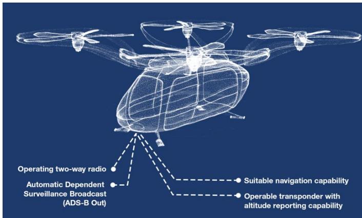
one-on-one outreach with individual applicants, and larger groups via forums to achieve a successful collaboration. This is a key procedural step in setting common expectations across the industry.
The FAA is engaged in rulemaking to enable AAM operations. The efforts are currently oriented around piloted operations, and in the interim the agency expects to use waivers, deviations, and exemptions as appropriate for initial operations. For AAM operations to be successful in 2028, it is important to connect, as seamlessly as possible, the interim methods with proposed rulemaking (and an overall framework, including external and internal guidance) as operational experience accrues.
## Rulemaking Activities
Integration of Powered Lift: Pilot Certification and Operations: Publication of a Notice of Proposed Rulemaking (NPRM) is expected in June 2023. This action proposes an SFAR for alternate eligibility requirements to safely certificate initial groups of powered lift pilots, as well as determine which operating rules to apply to powered lift aircraft on a temporary basis to enable the FAA to gather additional information and determine the most appropriate permanent rulemaking path for these aircraft.
Recognition of Pilot in Command Experience in the Military and Air Carrier Operations: The final rule was published on September 21, 2022. This action extended the 500-hour credit military pilots of fixed-wing airplanes can use towards the 1,000 hours of air carrier experience to pilots of powered lift aircraft operations. This allows credit for select military time in a powered lift aircraft flown in horizontal flight towards the 250 hours of airplane time as pilot in command (PIC), or second in command performing the duties of PIC, required for an airline transport pilot certificate.
Update to Air Carrier Definitions: This NPRM was published on December 7, 2022, with comments submitted by February 6, 2023. This action proposes to amend the regulatory definitions of certain air carrier and commercial operations. The proposed rule adds powered lift to these definitions to ensure the appropriate sets of rules apply to air carriers' and certain commercial operators' operations of aircraft that FAA regulations define as powered lift. The FAA also proposes to update certain basic requirements that apply to air carrier oversight, such as the contents of operations specifications and the qualifications applicable to certain management personnel. In addition, this action proposes to apply the rules for commercial air tours to powered lift. This proposed rule is an important step in the FAA's integration of this new entrant aircraft in the NAS.
Airman Certification Standards and Practical Test Standards for Airmen; Incorporation by Reference: This NPRM was published on December 12, 2022, with comments submitted by February 10, 2023. This action proposes to revise certain regulations governing airman certification. Specifically, the FAA Airman Certification Standards and Practical Test Standards are currently utilized as the testing standard for practical tests and proficiency checks for persons seeking or holding an airman certificate or rating. The FAA proposes to incorporate these Airman Certification Standards and Practical Test Standards by reference into the certification requirements for pilots, flight instructors, flight engineers, aircraft dispatchers, and parachute riggers.
The following list includes examples of guidance that may need to be developed or updated in support of AAM integration rulemaking activities to describe standards and means of compliance, as well as promote good safety practices. This list is not all-inclusive.
Advisory Circulars
Development of standards and practices for Flight Standardization Boards and Maintenance Review Boards
• Processes and Procedures for issuance of 14 CFR part 135 Air Operator Certificates
• Amendment of internal FAA Orders and related change management
• FAA Order 8900.1 Flight Standards Information Management System
FAA Order 8260-series
• Development of training for workforce to support AAM oversight and certification
Development of and guidance related to the issuance of Operations Specifications (OpSpecs), Management Specifications (MSpecs), Training Specifications (TSpecs), and Letters of Authorization as appropriate, for AAM Operations
• Guidance and procedures for the issuance of licensing and certification of industry personnel
• Aeronautical Information Manual (AIM) and Aeronautical Information Publication (AIP)
Pilots Handbook of Aeronautical Knowledge
Flight Standards infrastructure guidance
Flight Standards is working to further adapt its organizational structure for both conventional and emerging operations. Aircraft capabilities and procedures (defined by manufacturers) are inextricably linked with operational approvals and personnel training, along with procedures for flight operations and continued airworthiness. As such, Flight Standards will continue to work closely with the FAA’s Aircraft Certification Service (AIR) as part of an integrated oversight strategy by dovetailing its efforts with the certification of AAM aircraft and the issuance of Type Certificates (and continuous operational safety after entry into service).
Flight Standards is evolving its tools used for coordination of manufacturer/operator applications to increase efficiencies and enhance communications. For simple certifications, some steps can be condensed or eliminated. Some applicants may lack a basic understanding of what is required for certification. Other applicants may propose a complex operation but are well prepared and knowledgeable. Because of the variety in proposed operations and differences in applicant knowledge, processes will be thorough and flexible enough to apply to all possibilities. Industry applicants have the responsibility for compliance. Flight Standards will ensure applicants are aware of applicable regulations, standards, and requirements.
Flight Standards is making improvements to the prioritization and processing of certification of new operators and repair stations. This includes exploring various ways to reduce wait times, while ensuring resources available to support valid business ventures. Similarly, as with conventional aviation and drone operations, surveillance and oversight will be scaled taking a risk-based approach, ensuring application of the right level of FAA (and industry) resources. For cases where direct oversight is not applied as frequently, the FAA will work with industry on broad safety promotion and compliance activities.
## 5.2.2 Aircraft Certification
Aircraft certification is a process through which the FAA approves the design, production, and airworthiness of aircraft in the U.S. The certification process ensures that an aircraft meets minimum safety and environmental standards set by the FAA before it can be operated commercially or privately in the U.S. airspace.
The certification process involves several stages, including design approval, production approval, and airworthiness approval. Design approval involves reviewing and approving an aircraft's proposed design, including its systems, structures, and performance capabilities. Production approval ensures that an aircraft is built according to the approved design and meets the FAA's quality standards. Finally, airworthiness certification ensures that the aircraft is in a condition for safe operation and conforms to its approved design.
Currently, AIR is engaged with over two dozen manufacturers targeting the development of novel aircraft and propulsion technologies that underlie the design and operation of AAM aircraft. While some of these companies are relatively early in their technology development, vehicle design, and operations concepts, and in their readiness to engage in a new type certification program, nearly half of the companies have reached a level of maturity and development to have manufactured flying testbed prototypes. Their progress reflects positively on readiness to advance in the type certification process.
AIR is also currently working to define clear certification requirements and pathways to showing compliance for several novel aircraft technologies that are anticipated to be key to the future of AAM design and operations. These technologies include electric propulsion, large lithium-ion battery arrays, hydrogen fuel cell systems for electrical energy supply, distributed propulsion systems with highly integrated flight and propulsion controls, increased automation, and VTOL capabilities for winged aircraft.
The FAA determined that its existing aircraft certification processes are sufficient to type certificate powered lift as a special class under 14 CFR § 21.17(b). The special class process allows the FAA to address the novel features of unique and nonconventional aircraft without the need for additional processes such as special conditions or exemptions that would be required if the FAA used existing airworthiness standards. Under the special class process, the FAA designates or creates applicable airworthiness requirements as the certification basis for each aircraft design, including its engines and propellers. This designation and creation of applicable airworthiness requirements includes appropriate requirements from the existing airworthiness standards applicable to normal category and transport category airplanes, normal category and transport category rotorcraft, aircraft engines and propellers (parts 23, 25, 27, 29, 33, and 35), and it may also include unique airworthiness criteria developed specifically for the individual product.
In order to move forward to a more streamlined certification process, the FAA has proposed an update and expansion of the requirements for Safety Management Systems (SMS) and requires 14 CFR parts 5, Safety Management Systems, 21, Certification Procedures for Products and Articles, 119, Certification: Air Carriers and Commercial Operators, 91, and 135 certificate holders to develop and implement an SMS. The FAA also proposed this rule in part to address a Congressional mandate as well as recommendations from the National Transportation Safety Board (NTSB) and two Aviation Rulemaking Committees (ARCs). The Notice of Proposed Rulemaking on Safety Management Systems was published in the Federal Register on January 11, 2023, and the comment period closed on April 11, 2023.
## Acceptable Means of Compliance
A key tenet of the FAA’s approach to AAM certification is that an applicant’s means of demonstrating compliance with the airworthiness requirements for its proposed design (i.e., the applicant’s Means of Compliance (MOC)) must be accepted by the FAA. Although the FAA is leveraging the performance-based requirements from 14 CFR part 23 as modified by amendment 23-64, the consensus standards that the FAA has accepted as MOCs for normal category airplanes may not be appropriate for a particular proposed AAM due to its configuration, complexity, or novel technology. Work is still in progress to provide applicants with standardized MOCs that consider configuration differences, complexity, and novel design.
## Noise Considerations
Aviation noise remains one of the primary environmental challenges to the continued growth of aviation. Pursuant to 49 U.S. Code (U.S.C.) 44715, the FAA has the responsibility to “protect the public health and welfare from aircraft noise.” This responsibility includes broad authority to adopt regulations and noise standards as necessary. The FAA regulates the maximum noise level that an individual civil aircraft can emit through requiring aircraft to comply with certain noise limits. These limits and associated testing standards are found in 14 CFR part 36, Noise Standards: Aircraft Type and Airworthiness Certification. Any applicant seeking a type certificate for their aircraft in the U.S. must comply with noise standard requirements as a part of the type certification process.3 In addition, the FAA must complete a Noise Control Act finding, which ensures that the latest safe and airworthy noise reduction technology is incorporated into aircraft design and enables the reductions in noise experienced by communities.
When establishing the noise certification basis for AAM, the FAA will examine each application and determine whether existing part 36 requirements are appropriate as a noise certification basis, as is done for all applicants whose aircraft are subject to noise certification. If the current standards cannot be appropriately applied, the FAA may promulgate a rule of particular applicability for that applicant’s aircraft model to establish a noise certification basis. Such a rule will require environmental review pursuant to the National Environmental Policy Act (NEPA). To date, for the one aircraft presented for noise certification, the FAA has determined that the existing testing procedures and requirements in part 36 are applicable. The FAA is currently evaluating other applications and will determine the noise certification basis for them.
## 5.3 Airspace and Air Traffic Management
AAM infrastructure, automation, and traffic management approaches will evolve over time as the AAM operational tempo increases in airspace across the NAS. AAM aircraft will be integrated at greater scale with commercial and general aviation (GA) traffic, as well as other low-altitude airspace users, such as recreational and commercial small unmanned aircraft systems or drones. In the near-term for I28, however, these interactions are minimized and thus can be managed with existing ATC tools, procedures, and protocols. AAM aircraft are expected to be operating with a pilot on board and under VFR in VMC conditions; it is likely these aircraft will be treated as any other fixed wing/rotorcraft operating under VFR conditions, to the extent they are able to comply with existing rules, regulations, and procedures.

The FAA’s Air Traffic Organization (ATO) leads the planning, development, and implementation of airspace and ATM solutions, including development of airspace and route structures, policies, procedures, and ATC training. For I28, the ATO developed a general approach for airspace route design and usage, and traffic management that supports AAM VFR operations in the near-term (see Section 4), including the use of existing VFR route constructs.
I28 ATM processes will support a future national strategy, and supplemental directives will ensure consistency in how AAM route networks are designed. Existing mechanisms used by air traffic beyond traditional airspace classifications include the establishment of a special air traffic rule which applies within a Special Flight Rules Area (SFRA). Evaluation of these and alternative methods early in the planning process will allow the required collaboration to ensure timely resolution and publication of AAM route and network design.
Depending on the volume and specific operational needs of I28 operations, local air traffic facilities may need to update their procedures, utilize existing non-rulemaking airspace strategies, and complete an analysis to determine the need for airspace changes. The air traffic planning and analysis policy uses an interdisciplinary approach to effectively manage NAS changes. This would include the development of necessary training in a training delivery plan.
Sufficient time will be allotted throughout I28 development activities to ensure the necessary rulemaking or non-rulemaking activities, route publications and distribution, and training materials can be developed; and controller training can be completed to support the safe management of NAS operations.
In parallel, the ATO will continue to address AAM through its ATO AAM Near-Term Operational Integration Workgroup (NTIWG), which was established in November 2021 to identify air traffic considerations and impacts for near-term operations. After concluding their review in June 2022, the NTIWG had identified 55 recommendations to help address the integration of AAM operations in the near-term. Many of the recommendations require changes to FAA policy and guidance directives including, but not be limited to:
JO 7110.65 Air Traffic Control
• JO 7210.3 Facility Operation and Administration
• JO 7400.2 Procedures for Handling Airspace Matters
The ATO also recommends a detailed policy review be conducted to determine if other associated orders and ACs need to be updated or developed. Topics that should be considered include:
Wake Turbulence Categorization and impacts to operations
• Aircraft Certification and how that translates to ATC Service Provisions and Separation
Minimum Safe Altitude as it applies to AAM
Workforce and facility staffing considerations
## 5.4 Infrastructure
AAM operations require specialized infrastructure to support the safe and efficient operation of eVTOL aircraft. This section addresses how existing infrastructure can be leveraged to support near-term operations. It also documents what has been completed to-date to enable the planning, design, and construction of new vertiports or modification of existing facilities. The FAA remains committed to fostering collaboration with industry and local stakeholders to enable vertiport construction. Additional aspects of infrastructure will need to be addressed as I28 efforts progress, including electrification to support charging of AAM aircraft and power for AAM operations. The DOT Interagency Working Group will address these and other topics not directly in the FAA’s purview.
## 5.4.1 Existing Infrastructure
To enable near-term operations, operators and manufacturers desire to use existing infrastructure, including commercial service airports, underutilized GA airports, and heliports. It is likely though that existing heliports and airports will require modification or enhancements to accommodate early entry aircraft and their unique operations.
Facility owners and operators should plan for dedicated takeoff and landing areas and support facilities that address the needs of eVTOL operators, including limited taxi capabilities and charging. Airport and heliport owners should engage existing and future tenants who intend to operate eVTOL aircraft to ensure planning and siting of infrastructure and equipment adequately accommodates their intended operations.
Construction of on-airport vertiport facilities may require FAA notification under 14 CFR part 77, Safety, Efficient Use, and Preservation of Navigable Airspace and updates to an airport’s FAA approved Airport Layout Plan (for federally obligated airports). Modifications to existing federally obligated infrastructure will also undergo FAA environmental review and community engagement. Facilities that do not require FAA approval or funding may be responsible for community engagement consistent with local rules.
## 5.4.2 New Infrastructure
Communities, developers, and operators may also choose to establish new vertiports, not co-located with an existing airport or heliport. State licensing and local zoning ordinances may require updates to accommodate these new types of landing facilities. Where no federal funding is used, FAA oversight and engagement with these new vertiports and their surrounding communities may be limited. Communities are encouraged to plan for vertiports capable of accommodating multiple operators that will benefit passengers. They should also plan for equitable, multimodal placement of vertiports to connect transportation systems without creating new sources of traffic congestion and parking concerns whenever possible. Construction of new infrastructure would trigger FAA notification under 14 CFR part 157.
## 5.4.3 Vertiport-Related Research
In 2019, the Office of Airports (ARP) and the Airport Technology Research and Development Branch (ATR) began a multi-year research project to support the development of vertiport standards. ATR is investigating and evaluating VTOL and STOL aircraft design and performance to develop design standards and guidance.
For Phase 1, ATR completed a literature review (2021) that identified gaps in available performance data; a result of AAM company concerns about the release of proprietary information. With the help of FAA’s Emerging Technology Coordination Branch (formerly known as Center for Emerging Concepts and Innovation) and other AIR offices, using existing mechanisms for communication with applicants and data protection, ATR obtained preliminary AAM aircraft data. The literature review findings, analysis of the aircraft data, and further interchange with manufacturers and operators, supported the development of interim guidance. On September 26, 2022, ARP released EB #105, Vertiport Design. The EB serves as interim guidance to airport sponsors, vertiport operators, and infrastructure developers for the design of vertiports for VTOL operations, until a performance-based AC is released in 2025. The EB is prescriptive and purposely limited to address eVTOL operations using design and performance data available from VTOL aircraft manufacturers currently working toward certification.
Phase 2 of the research was completed in summer 2022 and involved six hypothetical vertiport locations covering a range of diverse scenarios, including on-airport, off-airport (in close proximity to complex airport environment), urban, and rural vertiport environments. Modeling analyzed TLOF occupancy times for arrival and departure operations. The scenarios used site-specific information, allowing development of conceptual layouts for each scenario in an airport layout plan-style drawing.
Phase 3 of the research (started in January 2023) included simulation exercises and operation testing with various AAM companies. The simulation exercises will support preparations for on-site operational testing which will further evaluate landing precision, approach/departure profiles, rotorwash/downwash impacts, and aircraft taxiing.
The FAA also has an interagency agreement with the Department of Energy’s National Renewable Energy Lab (NREL) to determine how aircraft electrification affects a vertiport, heliport, or airport’s electrical grid. The research will look at vertiport charging requirements, hazards associated with charging stations, and cybersecurity.
Collaboration among FAA organizations and research branches has been key to ensuring FAA research is relevant and addresses the variety of operations anticipated for I28 and beyond. ARP receives notification of new and innovative aircraft and technology through the AIR Intake Board and other collaborative processes, and then facilitates introductions, as needed, between AIR, the manufacturer, and ATR. The FAA iTeams will continue to coordinate and collaborate on research areas of overlap.
To enable near-term operations, the following areas require further research:
• Vertiport fire extinguishment equipment and electric aircraft firefighting tactics
• VTOL aircraft parking needs
• Vertiport signage, markings, and lighting
## 5.4.4 Vertiport Standards and Oversight
The FAA is using existing policy, regulations, and infrastructure as a baseline for vertiport guidance and regulations development; however, it will be the responsibility of the operators, manufacturers, state and local governments, and other stakeholders to plan, develop, and enable vertiport infrastructure for I28 operations.
The FAA cancelled its AC on Vertiport Design in 2010 due to a lack of commercially available aircraft. Standards are needed to address the wide variety of aircraft and operations intended under AAM. While the FAA published prescriptive interim guidance for the design of vertiports in EB #105 in September 2022, ARP plans to release a performance-based AC in 2025. Data obtained through operational testing of prototype and production VTOL and STOL aircraft will greatly influence design standards and guidance in the AC. Since AAM is constantly evolving, ARP anticipates updating the vertiport AC more frequently than other airport-related ACs.
The FAA also established a cross-LOB/staff office ‘Vertiport Process Improvement Team’ to identify a path forward with developing criteria and standards for processing and analyzing proposed vertiports. This team identified actions necessary to address gaps in existing policies, procedures, and standards, including but not limited to the following:
Initiate a rulemaking project for 14 CFR parts 77, Safe, Efficient Use, and Preservation of the Navigable Airspace, and 157 to clarify applicability to vertiports and supporting infrastructure and define vertiport imaginary surfaces
Review and update JO 7400.2 Airport Airspace Chapter to address vertiport infrastructure and imaginary surfaces
Review and update FAA Forms 7460-1 and 7480-1 to identify and address vertiport/supporting infrastructure information and data needed for FAA processing/review
Define FAA’s role in vertiport inspections
Existing statutory authority may limit the agency’s ability to regulate (i.e., 14 CFR part 139, Certification of Airports) and fund vertiports, particularly for private-use facilities. Without certification or federal funding, facilities may not comply with FAA design standards (a current condition that exists in many heliports) or have similar safety equipment and firefighting equipment onsite like today’s commercial service airports.
## 5.5 Environment
The FAA is responsible for evaluating the significance of environmental impacts for aviation operations in the U.S. and disclosing those impacts to the public. As such, to enable nearterm AAM operations, the FAA will consider the impact of AAM aircraft on a variety of aspects of the human environment, including (but not limited to) noise, air quality, visual disturbances, and disruption to wildlife. The FAA has policies and practices in place to conduct environmental review for legacy aviation. However, the FAA is still evaluating how best to streamline the environmental review process for new entrants, such as AAM.

The majority of questions related to compliance with environmental requirements in support of I28 remain open due to the need for additional information on what FAA approvals will be required for different aspects of the operation and any infrastructure, and what FAA offices will be responsible for such approvals. In addition, further information from manufacturers and operational data for aircraft is needed for the analysis of noise and emissions impacts. In particular, in order to determine whether compliance with NEPA is required, the FAA will need to identify whether there is/are a major federal action(s) triggering NEPA. Certification of aircraft, such as AAM, is a major federal action that will trigger compliance with NEPA, however there may be other FAA actions (e.g., approving or establishing where the AAM aircraft fly) that could trigger NEPA. For example, developing routes for AAM aircraft or introducing AAM into the NAS that will impact other flight operations may trigger NEPA. If NEPA applies, the LOB responsible for the approval will need to determine and conduct the appropriate level of environmental review (including potentially public involvement), as well as consider the need for supplementary community engagement.4
The FAA’s Office of Environment and Energy (AEE) and the Office of the Chief Counsel (AGC) will provide support and advice to FAA LOBs in identifying applicable actions and determining the appropriate level of environmental review and associated public involvement and community engagement. If environmental reviews are required, the applicable LOB(s) will be responsible for planning, coordinating, and (where applicable) funding the environmental review and provide any associated public involvement and community engagement needed.
## 5.6 Hazardous Materials Safety
As AAM operations are initially expected to be conducted under 14 CFR part 135, AAM operators will be required to have hazardous materials training programs approved by the FAA; hazardous materials manuals accepted by the FAA; and Operations Specifications permitting or prohibiting accepting, handling, and transporting HazMat. These requirements apply whether or not a part 135 certificate holder chooses to transport hazardous materials. Part 135 HazMat training and manual requirements are functionbased and scale to the scope and complexity of a certificate holder’s operation.
DOT Hazardous Materials Regulations (HMR; 49 CFR parts 171-185) apply to any operator transporting hazardous materials in commerce. The HMR are promulgated by the Pipeline and Hazardous Materials Safety Administration (PHMSA). Regulations applicable to aviation are promulgated in coordination with the FAA.
As part of an operator’s SMS, safety risk assessments accounting for hazardous materials being transported, relative to a specific certificate holder’s system, can help to inform supplemental risk management strategies in AAM operations.
## 5.7 Community Engagement
Changes in airport operations, airspace procedures, aviation infrastructure, and technology can have effects on communities. When developing a new project or procedure that may impact the public, the FAA proactively engages with airports, communities, and elected officials to better understand community concerns about aviation noise and in some cases adjust or mitigate these concerns. With AAM, the FAA will proactively engage with airports and elected officials to ensure they understand AAM and expected operations. Currently the scope of what may need to change to accommodate the safe integration and operation of AAM operators into the airspace is evolving. The FAA’s level of engagement will follow the level of change; however, given the expected scope of AAM changes, the FAA does not expect the same type of engagement that the agency conducts for major airspace changes.
Engagement at the regional level is the most effective path as AAM stakeholders and the FAA consider key site locations for I28. The FAA’s Community Involvement Manual provides flexible guidance and best practices applicable to all FAA actions and will be leveraged for AAM operations and I28. Additional guidance also exists specifically related to airspace procedures. While the FAA does not expect to develop new or unique agency policy, it will be important to ensure all aspects of the I28 project utilize these best practices.
Elements of community engagement are already part of normal business practices for some FAA LOBs or Staff Offices. For example, compliance with NEPA and other environmental requirements often includes required public involvement elements, such as the distribution of an environmental document for public review and comment, that might be one element of a robust community engagement strategy. It is important to note that community engagement supplements but cannot substitute for these required public involvement activities. While public involvement is led by the FAA under some environmental laws or other requirements, community engagement may also be led by the proponent of the project (which may be FAA in the case of many airspace changes but can also be airport sponsors or operators). When the project proponent takes the lead on community engagement, the FAA plays an oversight role, providing advice and guidance on good community engagement practices.
For I28, community engagement needs to focus on more than just airspace and it will involve DOT/FAA and other agency offices. It is important that the public understand how these new aircraft operations will impact their communities. Many other stakeholders, such as AAM operators, vertiport sponsors, and airport operators, will be part of bringing AAM to an operational reality and will have a role in community engagement.
## 6 Innovate28 Integrated Schedule
The Integrated Master Schedule (IMS) contains a comprehensive list of activities that must be achieved by FAA LOBs and staff offices, industry, and local governments and stakeholders to enable AAM operations at a key site. The IMS is generic for a key site and will be tailored for each individual implementation, including the I28 building blocks, as more information is available. Not all activities included in the comprehensive generic IMS will be required for every implementation, and individual implementations will require additional site-specific activities. As a result, the IMS will be iterative as the team learns from each implementation. The IMS utilizes dependencies between activities which are included in Table 1. The IMS requires further refinement both within the agency and through collaboration with external stakeholders, including industry.
## The following lists some considerations for the IMS as displayed in Figure 1:
The Type Certification and Operational Certification paths shown in the IMS are examples for a typical OEM/operator. The certification timelines can vary significantly depending on the maturity and responsiveness of the OEM/operator. Some OEMs have already completed part(s) of the certification processes shown here.
The Environmental Review timeline is based off a typical Environmental Assessment. This timeline can range significantly based on site-specific factors that can either reduce the Environmental Review to a Categorical Exclusion when the proposed federal action does not individually or cumulatively have a significant effect on the human environment and the proposed action falls within the scope of the approved agency categorical exclusions; or increase it to an Environmental Impact Statement which is required under NEPA when a proposed federal action significantly affects the human environment.
The timelines of some activities could potentially be significantly reduced or eliminated if it is determined that existing infrastructure can be leveraged with little to no modification.
The final state of the IMS will list a duration and point of contact for each activity so its status can be tracked at routine check-in meetings.
Figure 1. Integrated Master Schedule Version 1.0
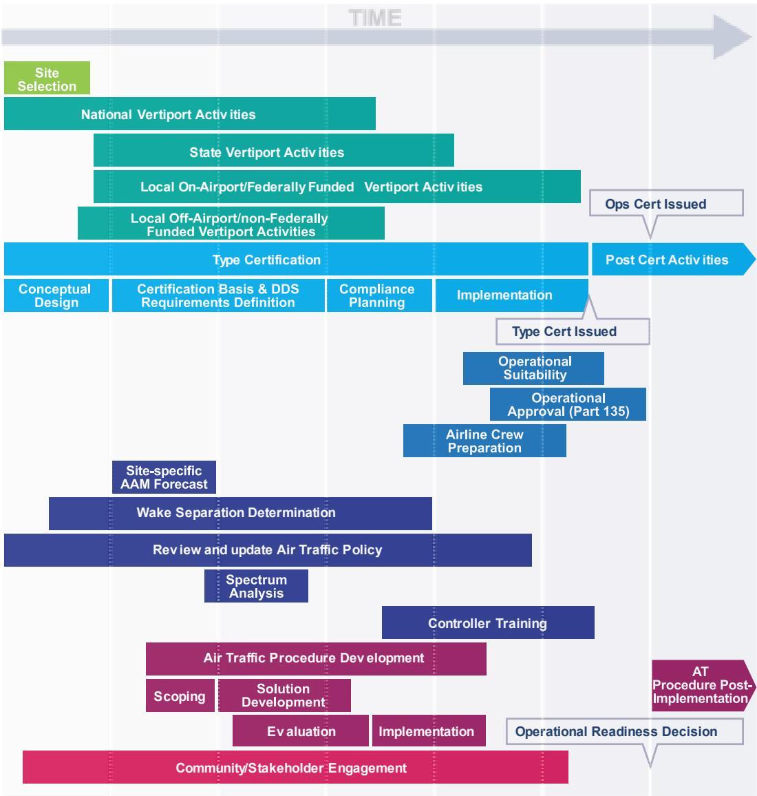
Note : The IMS is a depiction of the activities that may be required to allow an operator to enter into service at a location. Depending on the scope and concept of use for their planned operation, not all activities may be required for every implementation; the duration of a step may vary by project as well. Some companies have already completed some of these activities.
Table 1. Detailed List of Activities in the Integrated Master Schedule Version 1.0
| High-level Activity | Sub-activities | | High-level Activity | Sub-activities |
| Select Site | Local discussions and buy-in | | | | Operational Certification |
| National VertiportActivities | Vertiporteratinalestiatcollection and analysis | | | Operational Suitability |
| Vertiport AC | Vertiport ACRulemaking project fa157 | | Maintenance ReviewBoard (MRB) andReport (MRBR) |
| CodtiBoard(FOEB) |
| State VertiportActivities | Update zoning ordinances | |
| Update icensing requirements toaddress vertiports | | Issue Master Minimum EquipmentListing (MMEL) |
| State environmentalpolicy review | | Revifor Continued Airworthiness(CA's) |
| Local On-Airport/FederallyFunded VertiportActivities | Airport plannin actities | | ReviewandCocur ita FManuals nd Fight ManualSupplements |
| Airport Layout Plan (ALP)development, submission, andapproval process | | |
| Operational Approval(Part 135) | Phase 1: Pre-application |
| Section 163 reviewNEPA Environmental ReviewSite Engineering7460 processReceie statelicensin | Phase 2: Formal Application |
| Phase 3: Design Assessment |
| Phase 4: Performance Assessment |
| Phase5:Administative Function |
| ConstructionPublication and charting | | Review and Update AirTraffic Policy | 7110.65 Document Change Proposal(DCP) |
| Local Off-Airportinon-Federally FundedVertiport Activities | 7480 processReceie statelicensin | Revieandate40.Airspace Chapter |
| Design and Construction | | |
| Reviewand update FAA Foms7460-1and 7480-1 |
| Type Certification | | | Spectrum Analysis | |
| Conceptual Design | Process OrientationPre-Project GuidanceFamiliaization riefing | | Controller Training | Develop training plan |
| |
| Schedulecontrollr rainingTrain controllers |
| Develop and Ilmplement Air Trfi Procedure(s) |
| | Phase 1: Scoping | |
| Phase 2: ProcedureSolution Development (6months or more) | nitialdesiactiviteefinemnt,validation |
| Application | Aplication for TC and PCEstablishment of TC ProjectCetifictionPret Nic |
| Requirements | | |
| Definition | Form the Crtiction Team | | | | Initial Environmental look |
| | Phase 3: Evaluation 12-18months) | SMS/SRM Panel and Process |
| The Preliminary TCB eeting | | Environmental Review |
| Issue Paper ldentification | | | Phase 4: Implementation | Finalize SOP and LOA |
| Certification Basisand DDsRequirements'Definition | sis | G-1 Cetifiction Basis | | Procedure processing and publication,including fliht inpection |
| Notice of proposed airworthinesscriteria | | | | Charting |
| Aircraf ype auomationupe |
| G-2 Detailed DesignStandrds | | | | Phase 5: Post-Implementation | |
| G-3 Noise Standards | | |
| Mean/Method of Complince | | Wake SeparationDetermination | Develop performance data packagee.gei,fightcmandcontrolperformanceetc.) |
| CompliancePlanning | Review and Acceptance ofCertication Plans |
| Implementation | Conformity Inspections |
| Wake Separation Assessment |
| Detail-level compliance plan | | Update 7360.1 |
| Product-level complance plan | | Community/StakeholderEngagement | Messaging development |
| Website development |
| Safety Review Board | Continued Regional Office CommunityEnagflnroundtables) |
| TIA & Conformity Inspecion |
| Filight Testss | | |
| Airspace Implementation CommunityEngagement |
| Type Inpection Report | | | |
| | Final Type Certification Board | | | | |
| | | | Airline Crew Preparation | |
| | |
| Identify, vet, nd train e |
| Isse Type Cericate | | | Site-specific AAMforecast | |
| Post CertificationActivities | | |
| Rulemaking | Rulemaking for Pilo TrainingPowered-lift NPRM |
## 7 AAM Evolution Framework
The FAA’s approach to supporting the operationalization of AAM encompasses a series of incremental changes and advancements to the regulatory, technological, and operational frameworks that govern the NAS. This approach aims to ensure safety, while also facilitating efficiency and innovation in the AAM industry and will result in a continuum of AAM capabilities that evolves over time as the tempo of operations increases, driving the need for more advanced supporting infrastructure, regulations, and processes. This will allow the collection of early benefits and lessons learned while maintaining progress toward the fully mature state of AAM.
The agency is working on a regulatory framework that will allow AAM aircraft to be fully integrated into the airspace and operate alongside traditional aircraft in the near-term and beyond. The FAA and industry are developing the necessary technologies to support AAM operations, including aircraft and traffic management systems, communication networks, and autonomous capabilities. Finally, the FAA is working to establish operational frameworks that ensure the safe integration of AAM aircraft into the NAS, including training pilots, air traffic controllers, and other stakeholders on new procedures and regulations.
This evolutionary approach to AAM provides advantages. By initially supporting lower complexity operations in the near-term, as with I28, implementation can be achieved by maximizing the use of current capabilities that meet performance requirements and do not require full-scale regulatory and operational infrastructure changes.
With increased tempo, AAM operations will evolve through changes to governing regulations augmented by AAM infrastructure, automation, and cooperative traffic management practices supported by third party services. The evolution to a collaborative, information-rich, data-sharing environment will require new technologies and capabilities. AAM operators and other stakeholders will share information with the FAA having ondemand access to information as needed.
The FAA’s ANG organization developed an initial AAM framework that categorizes the evolving phases of AAM and provides context on the AAM roadmap to operationalization. The framework describes the anticipated operational capabilities for both FAA and industry stakeholders as the AAM ecosystem develops and matures over time. The framework also serves to identify key areas that require prioritization and coordination among the various stakeholders across the AAM ecosystem. The framework will inform FAA efforts, but also can be used by industry and other government agencies.
## AAM Coordination Areas
The AAM framework consists of five high-level coordination areas, shown in Table 2, within which key AAM capabilities pertaining to both FAA and industry stakeholders are highlighted. AAM capabilities are expected to progress independently toward a mature state. The pace of development may vary within and between coordination areas. Maturity is capability dependent, and not bound by a specific timeline. Regional maturity rates may vary as well, with some communities embracing AAM operations more rapidly than others.
It should be noted that community engagement, although not shown here, will be an integral and required step for each coordination area.
Table 2. AAM Coordination Areas
| Level | Description | Trigger Events (for reaching level) |
| 0 | Late-stage certification testing in limitedenvironments, aircraft certification testing andoperational evaluations with conformingprototypes and existing rules/procedures, andearly industry development and prototyping. | |
| 1 | Exploratory operations of minimal density andcomplexity, type certified aircraft, early FAAprocedures development, and initial Provider of Services for UAM (PSU) services. | Completion of relevant NPRMs andrulemaking to allow for vehicle typecertification, initial public standards to supportdata exchanges between industry participantsand the FAA. |
| 2 | Low-density scheduled commercial operations in urban areas and aroundairports, as well as an established federatedservice network* with several PSUs andSupplementary Data Service Providers(SDSPs). Designated cooperative airspace islimited (see UAM ConOps, Version 2.0).*A federated service network is one that isprovided and supported by the operators andthird-party service providers to exchange the information and agreements needed for FAA-approved cooperative operating practices. | Increased operational density, newoperational modes (e.g., remotely piloted),and the evaluation of cooperative airspaceand a federated service network with multipleoperating PSUs. |
| 3 | Medium-density scheduled and unscheduledcommercial operations using an increasednumber of vertiports and routes in specificgeographical areas that make continued use of limited, designated cooperative airspace.Established PSUs and federated servicenetworks support increased levels ofautomation and instances of remotely pilotedaircraft with a safety pilot on board. | Continued evolution of the modes ofoperations, implementation of designatedcooperative airspace in more geographicalareas, and the establishment of certificationstandards for automated and remotelyoperated large aircraft. |
| 4 | Medium-density scheduled and unscheduledcommercial operations in an AAM networkthat make widespread use of cooperativeairspace. Fully remotely-piloted operationsare supported. | Certification of fully remote piloted aircraftand the availability of enhanced CNScapabilities that can support long distanceand fully remote operations, complete implementation of new regulatory frameworks, widespread implementation ofcooperative airspace and vertiports, and theability to support operations in instrumentmeteorological conditions (IMC). |
| 5 | Mature AAM ecosystem, characterized byhigh density scheduled, unscheduled, andon-demand operations that aregeographically dispersed and served byaircraft able to operate autonomously. | Certification of fully autonomous aircraft andthe satisfactory performance of highlyintegrated automation within the federatedservice network. |
## FAA and Industry Coordination
The AAM evolution framework embraces independent advancement within coordination areas, but also acknowledges the need for coordination across the areas for the AAM ecosystem to come to fruition. It considers both FAA and industry activities and capabilities to support AAM maturation.
## Rulemaking
The FAA uses the same rulemaking process for AAM operations as it does for other aviation-related regulations. To carry out its responsibilities, the FAA must issue regulations that are clear and provide direction to the aviation industry and the public. Through the rulemaking process, the FAA engages with stakeholders, including industry groups, pilots, and the public, to develop regulations that are informed by their inputs. The process provides an opportunity for all interested parties to provide comments and feedback on proposed regulations, which helps to ensure that the final regulations are effective, practical, and above all, ensure safety.
## Standards Development
Industry stakeholders, including aircraft manufacturers, operators, and infrastructure providers, play a critical role in developing standards for AAM operations. Industry-driven standards are essential to ensure that AAM vehicles and infrastructure are safe, reliable, and interoperable. Long lead times and the level of stakeholder participation required to develop standards is a high priority area that requires establishing relationships among all the stakeholders, identifying standards development needs, and generating multi-year plans to address those needs and associated actions.
## Technology Development and Deployment
Industry’s development of technology often moves faster than the regulations addressing the use of the technologies. The FAA needs to establish and maintain close ties with industry to ensure that emerging technologies are designed with safety and NAS integration in mind and that regulations do not unduly constrain technology and market development. This includes the need for industry to consider the complexity of aviation operations and human factors, especially when proposing highly automated solutions. Additionally, the FAA needs to work closely with foreign regulatory counterparts and Air Navigation Service Providers to align and harmonize AAM-related regulations, policies and procedures, as applicable, given this sector’s global, entrepreneurial, and innovative ecosystem.
The long lead time for development and deployment of FAA capabilities also makes identifying FAA technology/capability requirements and establishing roadmaps for acquisition and development a high priority activity.
## Network Development
The mature state vision for AAM involves industry-built networks for data exchange to support many functions that the FAA has traditionally performed, including aspects of airspace management. These networks and the processes implemented for using them must be compatible with FAA data exchange mechanisms and airspace design and procedures.
## Airspace Design and Management
Initial AAM operations that are low density and low complexity will be conducted using existing airspace design and charting processes, and airspace constructs available today (e.g., VFR corridors/flyways, T-routes). As the operations continue to increase in volume and complexity, novel airspace design may be needed to accommodate operations. The concept of designating cooperative areas for AAM operations envisions safe and efficient operations that may not require traditional ATC services in certain situations. They will be available to any aircraft appropriately equipped to meet the performance requirements and are created and implemented when operationally advantageous.
## Moving Forward
The FAA will continue to work with AAM stakeholders to refine and further mature this framework and move towards an AAM ecosystem that supports innovation and scalability. The FAA is committed to ensuring the appropriate resources are allocated, workgroups are established to address areas that require research and development, and policy and regulatory decisions keep AAM moving forward into the future.
## Acronyms
| Acronym | Definition | Acronym | Definition |
| AAM | Advanced Air Mobility | IMC | Instrument Meteorological Conditions |
| AC | Advisory Circular | IMS | Integrated Master Schedule |
| ADS-B | Automatic Dependent Surveillance-Broadcast | 128 | Innovate28 |
| AGC | Office of the Chief Counsel | LOA | Letter of Agreement |
| AEE | Office of Environment and Energy | LOB | Line of Business |
| AFX | Flight Standards Service | MOC | Means of Compliance |
| AIM | Aeronautical Information Manual | MOU | Memorandum of Understanding |
| AIP | Aeronautical Information Publication | NAS | National Airspace System |
| AIR | Aircraft Certification Service | NASA | National Aeronautics and SpaceAdministration |
| ANG | Office of NextGen | NEPA | National Environmental Policy Act |
| ARC | Aviation Rulemaking Committee | NOTAM | Notice to Air Mission |
| ARP | Ooffice of Airports | NREL | National Renewable Energy Lab |
| ASOS | Automated Surface ObservingSystem | NTSB | National Transportation Safety Board |
|
| ATC | Air Traffic Control | OEM | Original Equipment Manufacturer |
| ATM | Air Traffic Management | NPRM | Notice of Proposed Rulemaking |
| ATO | Air Traffic Organization | PHMSA | Pipeline and Hazardous Materials SafetyAdministration |
| ATR | Airport Technology Research andDevelopment Branch | PIC | Pilot in Command |
| AWOS | Automated Weather ObservingSystem | PSU | Provider of Services for Urban Air Mobility |
| CFR | Code of Federal Regulations | SDSP | Supplementary Data Service Provider |
| CNS | Communications NavigationSurveillance | SFAR | Special Federal Aviation Regulation |
| DOT | Department of Transportation | SFRA | Special Flight Rules Area |
| EB | Engineering Brief | SMS | Safety Management System |
| EIS | Entry into Service | STOL | Short Takeff and Landing |
| EMS | Emergency Management Services | TFR | Temporary Flight Restriction |
| eVTOL | Electric Vertical Takeoff and Landing | TLOF | Touchdown and Liftoff Area |
| FAA | Federal Aviation Administration | UAM | Urban Air Mobility |
| GA | General Aviation | U.S.C. | United States Code |
| HMR | Hazardous Materials Regulation | VMC | Visual Meteorological Conditions |
| ICAO | International Civil AviationOrganization | VFR | Visual Flight Rules |


