# EASA PTS-VPT-DSN Vertiport Design

![665e1a19c32ab22da98fe62af8c3e7da63bd0983a5314e778e549ea56eb3f8fd.jpg](https://aam-wiki.gksj.cc/uploads/images/gallery/2026-05/scaled-1680-/665e1a19c32ab22da98fe62af8c3e7da63bd0983a5314e778e549ea56eb3f8fd.jpg)

Vertiports

Prototype Technical Specifications for the Design of VFR Vertiports for Operation with Manned VTOL-Capable Aircraft Certified in the Enhanced Category

(PTS-VPT-DSN)

March 2022

![6be03ee06aaf600f644ec27d6c07c24be0c5780d347514a2c08605d92e0417d3.jpg](https://aam-wiki.gksj.cc/uploads/images/gallery/2026-05/scaled-1680-/6be03ee06aaf600f644ec27d6c07c24be0c5780d347514a2c08605d92e0417d3.jpg)

Europe is at the forefront of a worldwide effort to enable new mobility concepts. The European aviation industry is already planning and investing in the development of new aircraft capable of vertical take-off and landing (VTOL) and in vertiports, which will be used as take-off and landing sites for those VTOL aircraft.

With this document, EASA is publishing the world’s first detailed prototype technical specifications for the design of vertiports (PTS-VPT-DSN) in the form of guidance. These prototype specifications describe in detail the physical characteristics of a vertiport, the required obstacle environment, visual aids, lights and markings, as well as concepts for en-route alternate vertiports for continued safe flight and landing.

Many of these vertiports will be built within an urban environment, and the EASA guidance therefore offers new and innovative solutions specifically for congested urban environments.

One notable innovation is the concept of a funnel-shaped area above the vertiport, designated as an obstacle-free volume. This concept is tailored to the operational capabilities of the new VTOL aircraft, which can perform landings and take-offs with a significant vertical segment. Depending on the urban environment and on the performance of certain VTOL-capable aircraft, omnidirectional trajectories to vertiports will be also possible. Such approaches can more easily take account of environmental and noise restrictions and are therefore more suitable for an urban environment than conventional heliport operations, which are more constrained in the approaches that can be safely applied. The guidance in this document has been developed under the leadership of EASA, working in cooperation with the world’s leading vertiport companies and VTOL manufacturers, and with the support of experts from European Member States. In a second step, EASA will develop a full regulatory framework for vertiport design and certification, operations, and oversight of vertiport operators in the context of a rulemaking task (RMT.230). For the rulemaking task EASA will make good use of its pivotal role in setting safety standards and developing regulatory frameworks. This will provide the basis for a global vertiport market to support the wide range of stakeholders involved in Urban Air Mobility including cities/communities, vertiport operators, VTOL aircraft manufacturers, Member States, and competent authorities.

We have a unique opportunity in aviation history to develop technical standards from scratch which will ensure that vertiports are safe and can be adapted to a succession of new VTOL aircraft types that we expect to be developed in the future. We invite you to offer your comments on this first edition of the prototype specifications for vertiports. Your feedback will help support our future rulemaking activities to enable safe vertiport design and operations.

## LEGAL DISCLAIMER:

All information provided in this Prototype Technical Specifications (PTS) for vertiports is of non-binding nature and is not intended to address specific circumstances of any one facility or organisation.

Its only purpose is to provide technical guidance, recommendations, and best practices without prejudice to officially adopted or future legislative and regulatory provisions, in particular future validated and finalised certification specifications adopted as a result of the respective rulemaking task (RMT.0230). It is not intended and should not be relied upon, as any form of warranty, representation, undertaking, contractual, or other commitment binding in law upon EASA. EASA does not express or imply any warranty or assume any liability or responsibility for the accuracy, completeness or usefulness of any information or recommendation included in the prototype technical specifications (PTS) for vertiports. To the extent permitted by Law, EASA shall not be liable for any kind of damages or other claims or demands arising out of or in connection with the use of the PTS.

## COPYRIGHT CLAUSE:

Copyright European Union Aviation Safety Agency, 2003-2022.

Ownership of all copyright and other intellectual property rights in this material including any documentation, data and technical information, remains vested to the European Union Aviation Safety Agency. All logo, copyrights, trademarks, and registered trademarks that may be contained within are the property of their respective owners.

## CONTACT NOTICE:

If you want to comment on the PTS, please contact EASA under the following address:

Flight Standards Directorate

Aerodromes Standards and Implementation Section (FS 2.4)

European Union Aviation Safety Agency

(EASA) Postfach 10 12 53, D-50452

Cologne,

Germany

Tel: +49 221 89990 1000

Email: aerodromes@easa.europa.eu

## PLACE AND DATE OF PUBLICATION:

EASA, Cologne, Germany, March 2022

Vertiports

# Prototype Technical Specifications for the Design of VFR Vertiports for Operation with Manned VTOL-Capable Aircraft Certified in the Enhanced Category

(PTS-VPT-DSN)

24 March 2022

Letter to urban air mobility (UAM) manufacturers, sent by the European Union Aviation Safety Agency (EASA) Vertiport Task Force (VPTTF) on 18 May 2021:

The EASA VPTTF, established for developing vertiport design requirements, addressed a letter to UAM manufacturers to gather sufficient data for developing vertiports’ design (VPT-DNS) specifications. The details of the request to manufacturers are explained below. EASA ensured that all data received was treated confidentially and not disclosed outside EASA or within the VPTTF without the explicit authorisation of the sender.

## VTOL-CAPABLE AIRCRAFT DATA SURVEY FOR DEVELOPING PROTOTYPE TECHNICAL SPECIFICATIONS FOR VERTIPORT DESIGN (prepared by the VPTTF)

## Notes:

The VTOL-capable aircraft considered in this document correspond to the ‘Category Enhanced’ as defined in EASA ‘Special Condition for small-category VTOL aircraft’1. In addition, the ‘Prototype Technical Specifications for Vertiports Design’ (PTS-VPT-DSN) are developed for manned vertical takeoff and landing (VTOL)-capable aircraft (EASA operations (OPS) Type#3).

According to EASA SC-VTOL-01, ‘vertiport’ means ‘an area of land, water, or structure used or intended to be used for the landing and take-off of VTOL-capable aircraft’. However, for the purpose of Aerodrome (ADR) and Vertiport (VPT) regulations, VPT should be classified as aerodrome by the definition.

Sensitivity and confidentiality of data: The VPTTF Focal Point (FP) ensures strict confidentiality of the received material within EASA. A sender of data may also allow the VPTTF FP to have insight into the replies sent to EASA on the draft means of compliance (MOC) for VTOL aircraft performance. Only with the sender’ s prior approval, received material (or part of it) may be shared within the VTPTF.

VTOL manufacturers are requested to provide information to better define the requirements for the design of the vertiport infrastructure.

The information provided will be used to evaluate the technical specifications for VTP-DSN and operation of VTOL-capable aircraft.

Information on VTOL-capable aircraft includes, but is not limited to, the following:

VTOL dimensions: shape/configuration, largest overall length and width, ‘D-value’;

VTOL maximum take-off mass (MTOM);

request for a lateral manoeuvring area during take-off from a final-approach and take-off area (FATO) to a take-off decision point (TDP) (including synthetic means, i.e. cameras to ensure the approach and take-off path);

approach/departure paths compared to obstacle limitation surfaces (OLSs), as provided in International Civil Aviation Organization (ICAO) Annex 14, Volume II, ‘Heliports’ (are those OLSs sufficient for the approach and take-off manoeuvres? — provide different requirements, if necessary);

rejected take-off distance (RTOD), characteristics of the load-bearing surface needed for rejected take-off (RTO);

landing gear geometry and dimensions, minimum ground turn radius;

VTOL taxiing, ground movement and parking requirements (specify the moving infrastructure for VTOL-capable aircraft, and whether the ‘D-value’ changes from landing to taxiing and parking);

visual angle in the vertical plane through pilot eye position (examples: Figures 2 and 3);

possible impact of battery charging/swapping procedures on taxiway and parking position design requirements;

downwash protection area to be considered (to allow safe operation and minimise hazards for ground personnel);

Note: To support the drafting of VPT-DSN specifications, the following information on the radial component of the downwash (‘outwash’) is required: VTOL manufacturers should report if while the aircraft is in a low hover at the limits of a cylinder volume of diameter 2 D around the VTOL-capable aircraft / from the ground/surface up to 1.5 m of height, the maximum measured radial speed is lower than 60 km/h in any wind conditions within the VTOL limit flight envelope (see EASA SC-VTOL-01, VTOL.2135). If the downwash temperature at those limits of the cylinder volume is more than 10°C above the ambient temperature, this should be also reported); and

minimum handling-area requirements around the VTOL-capable aircraft, including passenger handling and areas anticipated for the VTOL-capable aircraft services (i.e. battery charging, swap area, and the like).

SC-VTOL-01 and MOC: ‘D’ means the diameter of the smallest circle enclosing the VTOL aircraft projection on a horizontal plane, while the aircraft is in the take-off or landing configuration, with rotor(s) turning, if applicable (see Figure 1).

![f313036cdf4a068238a3b2c9aa3ed983bfc366bb46b67e7729c901febd4ec67d.jpg](https://aam-wiki.gksj.cc/uploads/images/gallery/2026-05/scaled-1680-/f313036cdf4a068238a3b2c9aa3ed983bfc366bb46b67e7729c901febd4ec67d.jpg)  
Figure 1. Dimension ‘D’

![8ad5265e777b91443116b0d5737cc4e0a26c9e9effedc882ffece7a1a3de25ee.jpg](https://aam-wiki.gksj.cc/uploads/images/gallery/2026-05/scaled-1680-/8ad5265e777b91443116b0d5737cc4e0a26c9e9effedc882ffece7a1a3de25ee.jpg)  
Figure 2. Visual angle in the vertical plane through pilot eye position (example)

![da916154a457fb8da9db270d1d2f9756abe0619839727c8d10ea4bec8d1661c4.jpg](https://aam-wiki.gksj.cc/uploads/images/gallery/2026-05/scaled-1680-/da916154a457fb8da9db270d1d2f9756abe0619839727c8d10ea4bec8d1661c4.jpg)

![3bb12b0f10d20da03091611037d741413dce2a60e27691165b6770f0d1ec9495.jpg](https://aam-wiki.gksj.cc/uploads/images/gallery/2026-05/scaled-1680-/3bb12b0f10d20da03091611037d741413dce2a60e27691165b6770f0d1ec9495.jpg)  
Figure 3. Illustration of helicopter CAT A approaches with angles higher than $30 ^ { \circ }$ from the horizontal plane

## TABLE OF CONTENTS

Table of contents ........   
List of abbreviations..... 10   
CHAPTER A — GENERAL ..... . 12   
PTS VPT-DSN.A.010 Applicability .... .... 12   
PTS VPT-DSN.A.020 Definitions..... ....................................................... ...... 14   
CHAPTER B — VERTIPORT DATA..... ...... 20   
PTS VPT-DSN.B.100 Aeronautical data.. .... 20   
PTS VPT-DSN.B.110 Vertiport reference point... ............................... .... 20   
PTS VPT-DSN.B.120 Vertiport elevation.. ... 21   
PTS VPT-DSN.B.130 Vertiport dimensions and related information... ..... 21   
PTS VPT-DSN.B.140 Vertiport declared distances.... .. 22   
PTS VPT-DSN.B.150 Coordination between aeronautical information services and   
vertiport authorities... .. 22   
PTS VPT-DSN.B.160 Safeguarding of vertiports . ..... 23   
CHAPTER C — PHYSICAL CHARACTERISTICS . .. 25   
PTS VPT-DSN.C.200 General. .. 25   
PTS VPT-DSN.C.210 Final-approach and take-off areas (FATOs).. .... 26   
PTS VPT-DSN.C.220 Safety areas.... ... 27   
PTS VPT-DSN.C.230 Downwash protection.......................................................... 28   
PTS VPT-DSN.C.240 Protected side slope.. ................. ... 30   
PTS VPT-DSN.C.250 VTOL-capable aircraft clearway ...... .................... ..... 31   
PTS VPT-DSN.C.260 Touchdown and lift-of area (TLOF) .. ... 31   
PTS VPT-DSN.C.270 VTOL-capable aircraft taxiways and taxi-routes .................. 33   
PTS VPT-DSN.C.280 VTOL-capable aircraft taxiways.... .. 33   
PTS VPT-DSN.C.290 VTOL-capable aircraft taxi routes.... ..... 34   
PTS VPT-DSN.C.300 VTOL-capable aircraft ground taxi-routes..... .......... ... 35   
PTS VPT-DSN.C.310 VTOL-capable aircraft air taxi-routes ........................... ..... 36   
PTS VPT-DSN.C.320 VTOL-capable aircraft stands . ... 37   
PTS VPT-DSN.C.330 VTOL-capable aircraft stand protection area..... ..... 41   
PTS VPT-DSN.C.340 Location of a final-approach and take-off area (FATO) in   
relation to another FATO ...... ..... 44   
PTS VPT-DSN.C.350 Location of a final-approach and take-off area (FATO) in   
relation to an aerodrome runway or taxiway....... ........ 45   
CHAPTER D — OBSTACLE ENVIRONMENT . . 46   
PTS VPT-DSN.D.400 Applicability .. .. 46   
CHAPTER D, Subpart 1 — OBSTACLE LIMITATION SURFACES .........47   
PTS VPT-DSN.D.405 General... ... 47   
PTS VPT-DSN.D.410 Approach surface.. ................... .... 52   
PTS VPT-DSN.D.415 Transitional surface .... ..... 54   
PTS VPT-DSN.D.420 Take-off climb surface ... 59   
PTS VPT-DSN.D.425 Application of obstacle limitation surfaces ................ ...... 60   
PTS VPT-DSN.D.430 Obstacle limitation requirements...... ........ 61   
CHAPTER D, Subpart 2 — OBSTACLE-FREE VOLUME... .... 62   
PTS VPT-DSN.D.440 General...... ...... 62   
PTS VPT-DSN.D.445 Generic volume...... ...... 62   
PTS VPT-DSN.D.450 Final-approach and take-off area (FATO) and safety area (SA)   
.... 64   
PTS VPT-DSN.D.455 Obstacle-free volume (OFV) . ... 65   
PTS VPT-DSN.D.460 Approach surface.. ..... 66   
PTS VPT-DSN.D.465 Take-off climb surface . ..................... ..... 66   
PTS VPT-DSN.D.470 Bidirectional volume..... ................................... ..... 67   
PTS VPT-DSN.D.475 Omnidirectional volume ........................................... ...... 67   
PTS VPT-DSN.D.480 Omnidirectional obstacle-free volume with prohibited sector   
... 70   
PTS VPT-DSN.D.485 Reference volume Type 1 .......... ........ 72   
PTS VPT-DSN.D.490 Link to VTOL-capable aircraft requirements.... ..... 76   
CHAPTER E — VISUAL AIDS............... ..... 80   
PTS VPT-DSN.E.500 Visual aids – General .... ..... 81   
PTS VPT-DSN.E.510 Wind direction indicator . .... 81   
PTS VPT-DSN.E.520 Vertiport identification marking... .... 83   
PTS VPT-DSN.E.530 FATO identification marking........... ................................... 86   
PTS VPT-DSN.E.540 Maximum allowable mass marking.. ................... ..... 88   
PTS VPT-DSN.E.550 D-value marking ...... ....... ..... 89   
PTS VPT-DSN.E.560 FATO perimeter marking or markers .... .... 90   
PTS VPT-DSN.E.570 FATO designation markings for runway-type FATOs . ... 92   
PTS VPT-DSN.E.580 Aiming point marking .............. ...... 93   
PTS VPT-DSN.E.590 TLOF perimeter marking ....... ...... 94   
PTS VPT-DSN.E.600 Touchdown positioning marking (TDPM). .. 94   
PTS VPT-DSN.E.610 Obstacle sector marking... ... 95   
PTS VPT-DSN.E.620 Vertiport name marking.. ... 96   
PTS VPT-DSN.E.630 VTOL-capable aircraft taxiway markings and markers.........97   
PTS VPT-DSN.E.640 VTOL-capable aircraft air taxi-route markings and markers   
.. 100   
PTS VPT-DSN.E.650 VTOL-capable aircraft stand markings ...... ... 101   
PTS VPT-DSN.E.660 Apron safety lines..... ... 104   
PTS VPT-DSN.E.670 Flight path alignment guidance marking....... .. 105   
PTS VPT-DSN.E.680 Visual aids for denoting restricted-use areas........ ...... 106   
PTS VPT-DSN.E.700 Lights — general.. ... 108   
PTS VPT-DSN.E.710 Vertiport beacon ...... .... 109   
PTS VPT-DSN.E.720 Approach lighting system.... ... 110   
PTS VPT-DSN.E.730 Flight path alignment guidance lighting system.. ... 112   
PTS VPT-DSN.E.740 Visual alignment guidance system . ..114   
PTS VPT-DSN.E.750 Visual approach slope indicator .. ..115   
PTS VPT-DSN.E.760 FATO lighting systems . .. 120   
PTS VPT-DSN.E.770 Aiming point lights . .. 122   
PTS VPT-DSN.E.780 TLOF lighting system .. 122   
PTS VPT-DSN.E.790 Vertiport identification marking lighting.. .. 125   
PTS VPT-DSN.E.800 The TLOF in a FATO lighting... .. 127   
PTS VPT-DSN.E.810 Vertiport stand floodlighting.. . 137   
PTS VPT-DSN.E.820 VTOL-capable aircraft stand lighting .. ..137   
PTS VPT-DSN.E.830 VTOL-capable aircraft taxiway/air taxi-route lighting........ 138   
PTS VPT-DSN.E.840 Visual aids for denoting obstacles outside and below the   
obstacle limitation surface.. .. 138   
PTS VPT-DSN.E.850 Floodlighting of obstacles.. .. 139

## LIST OF ABBREVIATIONS

(Used in PTS-VPT-DSN)
<table><tr><td colspan="1" rowspan="1">AFM</td><td colspan="1" rowspan="1">aircraft flight manual (a VTOL-capable AFM also refers to a helicopter flightmanual)</td></tr><tr><td colspan="1" rowspan="1">APAPI</td><td colspan="1" rowspan="1">abbreviated precision approach path indicator</td></tr><tr><td colspan="1" rowspan="1">ASPSL</td><td colspan="1" rowspan="1">arrays of segmented point source lighting</td></tr><tr><td colspan="1" rowspan="1">CAT</td><td colspan="1" rowspan="1">commercial air transport</td></tr><tr><td colspan="1" rowspan="1">cd</td><td colspan="1" rowspan="1">candelas</td></tr><tr><td colspan="1" rowspan="1">CFP</td><td colspan="1" rowspan="1">critical failure for performance</td></tr><tr><td colspan="1" rowspan="1">C/L</td><td colspan="1" rowspan="1">centre line</td></tr><tr><td colspan="1" rowspan="1">cm</td><td colspan="1" rowspan="1">centimetres</td></tr><tr><td colspan="1" rowspan="1">CS-ADR-DSN</td><td colspan="1" rowspan="1">Certification Specifications and Guidance Material for Aerodrome Design</td></tr><tr><td colspan="1" rowspan="1">CS-HPT-DSN</td><td colspan="1" rowspan="1">Certification Specifications and Guidance Material for the design of surface-levelVFR heliports located at aerodromes that fall under the scope of Regulation (EU)2018/1139</td></tr><tr><td colspan="1" rowspan="1">D</td><td colspan="1" rowspan="1">See PTS VPT-DSN.A.020 Definitions</td></tr><tr><td colspan="1" rowspan="1">D-value</td><td colspan="1" rowspan="1">a limiting dimension, in terms of D, for a vertiport or for a defined area within avertiport.</td></tr><tr><td colspan="1" rowspan="1">Design D</td><td colspan="1" rowspan="1">See PTS VPT-DSN.A.020 Definitions</td></tr><tr><td colspan="1" rowspan="1">DP</td><td colspan="1" rowspan="1">decision point</td></tr><tr><td colspan="1" rowspan="1">DR</td><td colspan="1" rowspan="1">horizontal distance that the helicopter has travelled from the end of the take-offdistance available</td></tr><tr><td colspan="1" rowspan="1">EASA</td><td colspan="1" rowspan="1">European Union Aviation Safety Agency</td></tr><tr><td colspan="1" rowspan="1">FATO</td><td colspan="1" rowspan="1">final-approach and take-off area</td></tr><tr><td colspan="1" rowspan="1">ft</td><td colspan="1" rowspan="1">feet</td></tr><tr><td colspan="1" rowspan="1">HAPI</td><td colspan="1" rowspan="1">helicopter approach path indicator</td></tr><tr><td colspan="1" rowspan="1">HEMS</td><td colspan="1" rowspan="1">helicopter emergency medical services</td></tr><tr><td colspan="1" rowspan="1">$Hz$</td><td colspan="1" rowspan="1">Hertz</td></tr><tr><td colspan="1" rowspan="1">ICAO</td><td colspan="1" rowspan="1">International Civil Aviation Organization</td></tr><tr><td colspan="1" rowspan="1">IFR</td><td colspan="1" rowspan="1">instrument flight rules</td></tr><tr><td colspan="1" rowspan="1">kg</td><td colspan="1" rowspan="1">kilograms</td></tr><tr><td colspan="1" rowspan="1">km/h</td><td colspan="1" rowspan="1">kilometres per hour</td></tr><tr><td colspan="1" rowspan="1">kt</td><td colspan="1" rowspan="1">knots</td></tr><tr><td colspan="1" rowspan="1">LDAV</td><td colspan="1" rowspan="1">landing distance available (for VTOL-capable aircraft)</td></tr><tr><td colspan="1" rowspan="1">LDRV</td><td colspan="1" rowspan="1">landing distance required (for VTOL-capable aircraft)</td></tr><tr><td colspan="1" rowspan="1">LDP</td><td colspan="1" rowspan="1">landing decision point</td></tr><tr><td colspan="1" rowspan="1">LED</td><td colspan="1" rowspan="1">light-emitting diode</td></tr><tr><td colspan="1" rowspan="1">LP</td><td colspan="1" rowspan="1">luminescent panel</td></tr><tr><td colspan="1" rowspan="1">lx</td><td colspan="1" rowspan="1">lux</td></tr><tr><td colspan="1" rowspan="1">m</td><td colspan="1" rowspan="1">metres</td></tr><tr><td colspan="1" rowspan="1">MTOM</td><td colspan="1" rowspan="1">maximum take-off mass</td></tr><tr><td colspan="1" rowspan="1">NVIS</td><td colspan="1" rowspan="1">night vision imaging system</td></tr><tr><td colspan="1" rowspan="1">OLS</td><td colspan="1" rowspan="1">obstacle limitation surfaces</td></tr><tr><td colspan="1" rowspan="1">PAPI</td><td colspan="1" rowspan="1">precision approach path indicator</td></tr><tr><td colspan="1" rowspan="1">PC</td><td colspan="1" rowspan="1">performance class</td></tr><tr><td colspan="1" rowspan="1">PTS-VPT-DSN</td><td colspan="1" rowspan="1">Prototype technical specifications for the design of VFR vertiports</td></tr><tr><td colspan="1" rowspan="1">R/T</td><td colspan="1" rowspan="1">radiotelephony or radio communications</td></tr><tr><td colspan="1" rowspan="1">RFFS</td><td colspan="1" rowspan="1">rescue and firefighting services</td></tr><tr><td colspan="1" rowspan="1">RTO</td><td colspan="1" rowspan="1">rejected take-off</td></tr><tr><td colspan="1" rowspan="1">RTOD</td><td colspan="1" rowspan="1">rejected take-off distance</td></tr><tr><td colspan="1" rowspan="1">RTODV</td><td colspan="1" rowspan="1">rejected take-off distance (for VTOL-capable aircraft)</td></tr><tr><td colspan="1" rowspan="1">RTODAV</td><td colspan="1" rowspan="1">rejected take-off distance available (for VTOL-capable aircraft)</td></tr><tr><td colspan="1" rowspan="1">RTODRV</td><td colspan="1" rowspan="1">rejected take-off distance required (for VTOL-capable aircraft)</td></tr><tr><td colspan="1" rowspan="1">S</td><td colspan="1" rowspan="1">seconds</td></tr><tr><td colspan="1" rowspan="1">SA</td><td colspan="1" rowspan="1">safety area</td></tr><tr><td colspan="1" rowspan="1">SARPS</td><td colspan="1" rowspan="1">Standards and Recommended Practices (ICAO)</td></tr><tr><td colspan="1" rowspan="1">t</td><td colspan="1" rowspan="1">tonne (1 000 kg)</td></tr><tr><td colspan="1" rowspan="1">TDP</td><td colspan="1" rowspan="1">take-off decision point</td></tr><tr><td colspan="1" rowspan="1">TODAV</td><td colspan="1" rowspan="1">take-off distance available (for VTOL-capable aircraft)</td></tr><tr><td colspan="1" rowspan="1">TODRV</td><td colspan="1" rowspan="1">take-off distance required (for VTOL-capable aircraft)</td></tr><tr><td colspan="1" rowspan="1">TDPC</td><td colspan="1" rowspan="1">touchdown positioning circle</td></tr><tr><td colspan="1" rowspan="1">TDPM</td><td colspan="1" rowspan="1">touchdown positioning marking</td></tr><tr><td colspan="1" rowspan="1">TLOF</td><td colspan="1" rowspan="1">touchdown and lift-off area</td></tr><tr><td colspan="1" rowspan="1">UCW</td><td colspan="1" rowspan="1">undercarriage width</td></tr><tr><td colspan="1" rowspan="1">VFR</td><td colspan="1" rowspan="1">visual flight rules</td></tr><tr><td colspan="1" rowspan="1">VPT</td><td colspan="1" rowspan="1">vertiport</td></tr><tr><td colspan="1" rowspan="1">VPTTF</td><td colspan="1" rowspan="1">EASA Vertiport Task Force</td></tr><tr><td colspan="1" rowspan="1">VRP</td><td colspan="1" rowspan="1">vertiport reference point</td></tr><tr><td colspan="1" rowspan="1">VSS</td><td colspan="1" rowspan="1">visual-segment surface</td></tr><tr><td colspan="1" rowspan="1">VTOL</td><td colspan="1" rowspan="1">vertical take-off and landing</td></tr><tr><td colspan="1" rowspan="1">VTOSS</td><td colspan="1" rowspan="1">vertical take-of safety speed (for helicopters certified in category A)</td></tr><tr><td colspan="1" rowspan="1">Symbols</td><td></td></tr><tr><td colspan="1" rowspan="1">μ</td><td colspan="1" rowspan="1"> the coefficient of friction (u=Mu) is the ratio between the friction force and thevertical load</td></tr><tr><td colspan="1" rowspan="1">。</td><td colspan="1" rowspan="1">degrees</td></tr><tr><td colspan="1" rowspan="1">=</td><td colspan="1" rowspan="2">equalsper cent</td></tr><tr><td colspan="1" rowspan="1">%</td></tr></table>

# CHAPTER A — GENERAL

## PTS VPT-DSN.A.010 Applicability

## Rationale

1. The vertiport (VPT) rules will be developed in two stages: In the first stage, EASA will introduce the Prototype Technical Specifications as non-regulatory material for the design of VFR vertiports or parts thereof, applicable for the operation of manned VTOL-capable aircraft certified in the enhanced category (PTS-VPT-DSN, hereinafter ‘PTSs’). In the second stage, the rules will cover vertiports that are considered to be in the scope of Regulation (EU) 2018/1139 (the ‘Basic Regulation’): a full set of vertiport rules, including the authority, vertiport operator and vertiport operation requirements, will be introduced, along with the certification specifications (CSs) and guidance material (GM) for vertiport design and certification. The Basic Regulation (Article 2(1) (e)) defines the aerodromes (vertiports) that fall under its scope.

2. To be proportionate to the nature and risk of the activities performed at vertiports, VTOLcapable aircraft certified in the ‘Category Enhanced’ (see EASA SC-VTOL-01) are selected as reference for the developments of PTSs. The enhanced category (similar to performance class (PC) 1 of helicopters) allows proportionality in safety objectives and enables the highest level of safety in protecting third parties when flying over congested areas and when conducting commercial air transport (CAT) operations with passengers. VTOL-capable aircraft certified in the enhanced category must meet the requirements for continued safe flight and landing (CSFL) and be able to continue to the original intended destination or a suitable alternate vertiport after a failure.

3. EASA developed the PTSs at the request of Member States to introduce technical specifications for the design of vertiports, which Member States may use as input to their national regulatory frameworks for the design of vertiports.

4. The EASA VPTTF developed the PTSs based on the ADR rules (EU regulations and EASA certification specifications (CS-ADR-DSN and CS-HPT-DSN (Certification Specifications for Heliports)), as well as on ICAO Annex 14, Volume I, ‘Aerodromes’, Volume II, ‘Heliports’, ICAO Document 9261, Heliport Manual, and inputs from VTOL manufacturers and experts.

5. PTSs include objectives, applicability, characteristics, and location, which consist of one or more statements that describe(s) usage and limitations, attributes (without values or detailed specifications), and necessary associations. The values or attributes are normally specified with reference to the ‘design VTOL-capable aircraft’.

6. Each defined area is fully described along with its attributes, allowing it to be considered in isolation or in combination with other defined or subsidiary areas.

7. The PTSs are developed for the design of VFR vertiports or parts thereof for the operation of manned VTOL-capable aircraft certified in the enhanced category, carrying passengers or cargo.

8. It is assumed that VTOL-capable aircraft can operate at heliports or aerodromes if their performance can meet the design criteria of the heliport or aerodrome. However, the appropriate level of emergency equipment, e.g. for firefighting, which is determined by the level of the VTOL-capable aircraft operations at the heliport, should be ensured.

9. Applicability matrix of the PTSs
<table><tr><td rowspan=4 colspan=1></td><td rowspan=1 colspan=5>Aircraft certification according to SC-VTOL categories</td></tr><tr><td rowspan=1 colspan=3>Enhanced</td><td rowspan=1 colspan=2>Basic</td></tr><tr><td rowspan=1 colspan=2>Passenger transport</td><td rowspan=2 colspan=1>Cargo</td><td rowspan=2 colspan=1>Passenger(non-commercial)</td><td rowspan=2 colspan=1>Cargo</td></tr><tr><td rowspan=1 colspan=1>Commercial</td><td rowspan=1 colspan=1>Non-commercial</td></tr><tr><td rowspan=1 colspan=1>Mannedoperation</td><td rowspan=1 colspan=1>Yes</td><td rowspan=1 colspan=1>Yes</td><td rowspan=1 colspan=1>Yes</td><td rowspan=1 colspan=1>n/a</td><td rowspan=1 colspan=1>n/a</td></tr><tr><td rowspan=1 colspan=1>Unmannedoperation</td><td rowspan=1 colspan=1>n/a</td><td rowspan=1 colspan=1>n/a</td><td rowspan=1 colspan=1>n/a</td><td rowspan=1 colspan=1>n/a</td><td rowspan=1 colspan=1>n/a</td></tr></table>

Table A-1. Applicability matrix of the PTSs

## Yes: applicable.

n/a: outside the scope; however, vertiports designed according to that PTS may be used for such aircraft and/or use cases, unless they are subject to more demanding requirements stemming from other applicable standards or regulations.

‘Category Enhanced’ under SC-VTOL (hereinafter the ‘enhanced category’) is required for personcarrying VTOL operation over congested areas or for CAT pax operations.

‘Basic category’ is the opposite of the ‘enhanced category’, e.g. it covers non-CAT pax/cargo operations outside congested areas, CAT cargo operations outside congested areas, and training flights.

10. It is at the discretion of the competent authority to use the PTSs as a reference for the development of requirements for the design of vertiport infrastructure to serve unmanned operations or operations in the basic category for VTOL-capable aircraft.

11. The limiting dimensions that are provided for in ICAO Annex 14, Volume II, ‘Heliports’ and ICAO Document 9261, Heliport Manual, are based on the principle of the helicopter design and on statistical analysis of the population of helicopters, as described in Appendix A to Chapter 3 of the Heliport Manual. A similar analysis will be required for the VPT regulations, when all information from the VTOL manufacturers is available.

(a) The Prototype Technical Specifications (PTS-VPT-DSN) are developed as non-regulatory material for the design of VFR vertiports or parts thereof and are applicable for operation of manned VTOL-capable aircraft certified in the enhanced category.

(b) PTS-VPT-DSN contains technical specifications for physical characteristics, obstacle environment, and visual aids for the design of vertiport, and are not intended to limit or regulate the operation of VTOL-capable aircraft.

(c) For vertiport facilities located at aerodromes that fall under the scope of Regulation (EU) 2018/11391 (the ‘Basic Regulation’), and where relevant, CS-ADR-DSN and CS-HPT-DSN apply to the areas and infrastructure used by VTOL-capable aircraft.

(d) Unless otherwise specified, the colour specifications used in PTS-VPT-DSN are those contained in CS-ADR-DSN.

(e) When designing a vertiport, the following parameters should be considered:

the set of the largest dimensions

the maximum take-off mass (MTOM), and

the most critical obstacle avoidance criteria

of the population of VTOL-capable aircraft that the vertiport is intended to serve.

(f) The vertiport designer, operator, and user should be assured that when a VTOL-capable aircraft is within the D-value and maximum allowable mass (promulgated, and in most cases displayed on the FATO) and is operated in accordance with normal practice, all defined areas are safe to use.

Note: The maximum allowable mass represents a limitation on the actual mass of the VTOLcapable aircraft on arrival or departure.

## PTS VPT-DSN.A.020 Definitions

## Rationale

1. According to the MOC-2 SC-VTOL ‘D’ means the diameter of the smallest circle enclosing the VTOL aircraft projection on a horizontal plane, while the VTOL aircraft is in the take-off or landing configuration, with rotor(s) turning, if applicable. The operator should publish D in metres, rounded up to the next tenth. If the VTOL aircraft changes dimension during taxiing or parking (e.g. folding wings), a corresponding Dtaxiing or Dparking should also be provided (see also CAT.POL.H.110 of Annex IV (Part-CAT) to Regulation (EU) No 965/2012 (the ‘Air OPS Regulation’)2).

2. The definition of ‘distance DR’ (i.e. the horizontal distance that the VTOL-capable aircraft has travelled from the end of the take-off distance available (TODA) to the obstacle) will be used to define the DR for VTOL-capable aircraft i.e. the horizontal distance that the VTOL-capable aircraft has travelled from the end of the TODA to the obstacle or from the back of the FATO to the obstacle (see also CAT.POL.H.110).

3. To be proportionate to the nature and risk of the activities performed by VTOL-capable aircraft, two certification categories are introduced in the above SC VTOL, namely the ‘basic category’ and the ‘enhanced category’, which are linked to the intended type of operations. A direct relationship between airworthiness and types of operations already exists, for example when certifying for visual flight rules (VFR) or instrument flight rules (IFR) operations. Introducing this additional link allows proportionality in safety objectives and enables the highest level of safety in the enhanced category in protecting third parties when flying over congested areas and when conducting commercial air transport (CAT) operations of passengers. The operational rules can then be built on demonstrated aircraft safety levels and adapted as necessary to local particularities (see EASA SC-VTOL-01).

4. VTOL-capable aircraft certified in the enhanced category must meet the requirements for continued safe flight and landing (CSFL) and be able to continue to the original intended destination or a suitable alternate vertiport after a failure. For the basic category, only controlled-emergency landing requirements must be met, in a similar manner to a controlled glide or autorotation (see EASA SC-VTOL-01).

5. The types of operations that the enhanced-category aircraft perform correspond to the highest operational risk for third parties and/or for passenger transport for remuneration. For this reason, the most stringent system safety objectives are assigned regardless of the number of occupants. These safety objectives have been established based upon two complementary EASA evaluations, which converged on a numerical value of the same order of magnitude (see EASA SC-VTOL-01).

6. The definition of ‘charging facilities’ by the International Electrotechnical Commission (IEC), adapted to vertiports, is also provided.

For the purposes of PTS-VPT-DSN, the following definitions apply:

‘Aerodrome’ means a defined area (including any buildings, installations, and equipment) on land or water or on a fixed offshore or floating structure intended to be used either wholly or in part for the arrival, departure, and surface movement of aircraft.

‘Charging facility’ means a charging station that supplies alternating current (AC) and/or direct current (DC) to an electric aircraft for recharging its batteries, including, if needed, the connection between charging station and electric aircraft (refer to the International Electrotechnical Commission (IEC)).

‘Category Enhanced’ means a certification category for VTOL-capable aircraft according to which the aircraft meets the requirements for continued safe flight and landing (CSFL) after a critical failure for performance (CFP).

‘Category Basic’ means a certification category for VTOL-capable aircraft according to which the aircraft meets the requirements for controlled emergency landing after a critical failure for performance (CFP).

‘Clearway’, for VTOL-capable aircraft, means a defined area on the ground or water, selected and/or prepared as a suitable area over which a VTOL-capable aircraft that is certified in the enhanced category may accelerate and achieve a specified set of flight conditions.

‘Commercial air transport operation’ means an aircraft operation involving the transport of passengers, cargo, or mail for remuneration or hire.

‘Congested area’ means, in relation to a city, town, or settlement, any area that is substantially used for residential, commercial, or recreational purposes.

‘Continued safe flight and landing (CSFL)’ means, in relation to a VTOL-capable aircraft, that the aircraft is capable of continued controlled flight and landing at a vertiport, possibly using emergency procedures, without requiring exceptional piloting skill or strength.

‘D’, for helicopters, means the largest overall dimension of the helicopter, when rotor(s) are turning, measured from the most forward position of the main rotor tip path plane to the most rearward position of the tail rotor tip path plane or helicopter structure.

‘D’, for VTOL aircraft, means the diameter of the smallest circle enclosing the VTOL aircraft projection on a horizontal plane, while the aircraft is in the take-off or landing configuration, with rotor(s) turning, if applicable (see also PTS VPT-DSN.D.490 and Appendix 1).

Note: If the VTOL aircraft changes dimensions during taxiing or parking (e.g. folding wings), a corresponding $\mathsf { D } _ { \mathsf { t a x i i n g } } \mathsf { o r } \mathsf { D } _ { \mathsf { p a r k i n g } }$ should also be provided.

![5afb92d5754ca887fb75eef65d7656dcf05f7e4839e8221640811677424c9182.jpg](https://aam-wiki.gksj.cc/uploads/images/gallery/2026-05/scaled-1680-/5afb92d5754ca887fb75eef65d7656dcf05f7e4839e8221640811677424c9182.jpg)  
Figure A-1. Centre and diameter ‘D’ of the smallest enclosing circle

‘D-value’ means a limiting dimension, in terms of D, for a vertiport, or for a defined area within a vertiport.

‘Design D’ means the D of the design VTOL-capable aircraft.

‘Design VTOL-capable aircraft’ means the VTOL-capable aircraft type that the vertiport is intended to serve, which has the largest set of dimensions, the greatest maximum take-off mass (MTOM), and the most critical obstacle avoidance criteria. Those attributes may not reside in the same VTOL-capable aircraft capability.

‘Distance DR’ means the horizontal distance that the VTOL-capable aircraft has travelled from the end of the take-off distance available (TODA) to the obstacle or from the back of the final-approach and take-off area (FATO) to the obstacle.

‘Dynamic load-bearing surface’ means a surface capable of supporting the loads that are generated by a VTOL-capable aircraft in motion.

‘Elongated’ means, when used with touchdown and lift-off area (TLOF) or final approach and take-off area (FATO), an area which has a length more than twice its width.

‘Essential objects permitted’ includes, but may not be limited to, around the touchdown and lift-off area (TLOF), perimeter lights and floodlights, guttering and raised kerb, foam monitors or ring-main system, handrails and associated signage, other lights.

‘Elevated VTOL-capable aircraft clearway’ means a clearway raised to a level that provides obstacle clearance.

‘Heliport’ means an aerodrome or a defined area on a structure intended to be used wholly or in part for the arrival, departure, and surface movement of helicopters.

‘Landing distance available (LDAV)’, for VTOL-capable aircraft, means the length of the FATO plus any additional area that is declared available and suitable for VTOL-capable aircraft to complete the landing manoeuvre from a defined height.

‘Landing distance required (LDRV)’ for VTOL-capable aircraft, means the horizontal distance that is required for landing and coming to a full stop from a point that is 15 m (50 ft) above the landing surface.

‘Landing decision point (LDP)’, for VTOL-capable aircraft, means a point along the landing flight path, which is defined as the last point from which a balked landing can be performed. After the LDP, a balked landing is not ensured. If the aircraft is certified in the enhanced category, then a landing should be possible following a critical failure for performance (CFP) before or after the LDP.

‘Obstacle’ means all fixed (whether temporary or permanent) and mobile objects, or parts thereof, that: are located on an area intended for the surface movement of VTOL-capable aircraft; extend above a defined surface intended to protect VTOL-capable aircraft in flight; or stand outside those defined surfaces but, nonetheless, are assessed as a hazard to air navigation.

‘Protection area’ means a defined area, surrounding a stand, which is intended to reduce the risk of damage from VTOL-capable aircraft accidentally diverging from the stand.

‘Rejected take-off distance (RTODV)’, for VTOL-capable aircraft, means the length of the finalapproach and take-off area (FATO) that is declared available and suitable for VTOL-capable aircraft to complete a rejected take-off in accordance with the category (enhanced or basic) in which the aircraft is operated.

‘Rejected take-off distance available (RTODAV)’, for VTOL-capable aircraft, means the length of the FATO that is declared available and suitable for VTOL-capable aircraft to complete a rejected take-off in accordance with the category (enhanced or basic) in which the aircraft is certified.

‘Rejected take-off distance required (RTODRV)’, for VTOL-capable aircraft, means the horizontal distance that is required from the start of the take-off to the point where the aircraft comes to a full stop, following a critical failure for performance (CFP) that is recognised at the take-off decision point (TDP).

‘Runway-type FATO’ means a final-approach and take-off area (FATO) that has characteristics similar in shape to a runway.

‘Safety area (SA)’ means a defined area on a vertiport, which surrounds the final-approach and takeoff area (FATO) and is free of obstacles, other than those required for air navigation purposes, and which is intended to reduce the risk of damage to VTOL-capable aircraft accidentally diverging from the FATO.

‘Static load-bearing area’ means a surface capable of supporting the mass of the VTOL-capable aircraft that is situated upon it.

‘Take-off decision point (TDP)’, for VTOL-capable aircraft, means the first point that is defined by a combination of speed and height from which continued take-off can be made meeting the certified minimum performance (CMP) following a critical failure for performance (CFP), and is the last point in the take-off path from which a rejected take-off (RTO) is ensured.

‘Take-off distance available (TODAV)’, for VTOL-capable aircraft, means the length of the finalapproach and take-off area (FATO) plus the length of any clearway (if provided) that is declared available and suitable for VTOL-capable aircraft to complete the take-off.

‘Take-off distance required (TODRV)’, for VTOL-capable aircraft, means the projected horizontal distance from the start of the take-off to the point at which safe obstacle clearance and a positive climb gradient are achieved, following a critical failure for performance (CFP) recognised at the takeoff decision point (TDP).

‘Take-off flight path’, for VTOL-capable aircraft, means the vertical and horizontal path that extends from the take-off point to a point at which the aircraft is at 305 m (1 000 ft) above the take-off elevation or at such other height above the take-off elevation that allows the aircraft to clear all obstacles.

‘Touchdown and lift-off area (TLOF)’ means an area where a VTOL-capable aircraft may touch down or lift off.

‘Touchdown positioning circle (TDPC)’ means a touchdown positioning marking (TDPM) in the form of a circle, which is used for omnidirectional positioning in a touchdown and lift-off area (TLOF).

‘Touchdown positioning marking (TDPM)’ means a marking or set of markings that provide visual cues for the positioning of VTOL-capable aircraft.

‘Touchdown positioning marking (TDPM) circle’ means the reference marking for a normal touchdown, which is so located that when the pilot’s seat is over the marking, the whole of the undercarriage will be within the touchdown and lift-off area (TLOF) and all parts of the VTOL-capable aircraft will be clear of any obstacles by a safe margin.

‘Vertiport’ means an area of land, water, or structure that is used or intended to be used for the landing, take-off, and movement of VTOL-capable aircraft.

‘Vertiport elevation’ means the highest point of the final-approach and take-off area (FATO).

‘Vertical procedures’ means take-off and landing procedures that include an initial vertical/steep climb and a final vertical/steep descent profile. The profile may or may not include a lateral component.

‘Vertiport operator’ means any legal or natural person that is operating or proposing to operate one or more vertiports.

‘Vertiport reference point (VRP)’ means the designated geographical location of a vertiport.

‘VTOL-capable aircraft’ means a heavier-than-air aircraft, other than aeroplane or helicopter, capable of performing vertical take-off and landing by means of more than two lift/thrust units that are used to provide lift during the take-off and landing.

‘VTOL-capable aircraft taxiway’ means a defined path on a vertiport that is intended for the ground movement of VTOL-capable aircraft and that may be combined with an air taxi-route to permit both ground and air taxiing.

‘VTOL-capable aircraft stand’ means a defined area that is intended to accommodate a VTOL-capable aircraft for loading or unloading passengers, mail, or cargo, fuelling/charging, parking, or maintenance, and, for the TLOF, where air taxiing operations are contemplated, the TLOF.

‘VTOL-capable aircraft taxi-route’ means a defined path that is established for the movement of VTOL-capable aircraft from one part of a vertiport to another:

(a) an air taxi-route: a marked taxi-route that is intended for air taxiing; and

(b) a ground taxi-route: a taxi-route that is centred on a taxiway.

Where relevant, the definitions provided in CS-ADR-DSN and CS-HPT-DSN apply accordingly.

# CHAPTER B — VERTIPORT DATA

## PTS VPT-DSN.B.100 Aeronautical data

## Rationale

This Chapter B ‘Vertiport data’ is drafted with reference to and based on ICAO Annex 14, Volume II, ‘Heliports’, and ICAO Document 9261, Heliport Manual. Vertiport data and procedures, provided in this chapter, for coordination with the competent authorities and the aeronautical information services (AIS) are at this stage at the discretion of the national competent authorities (NCAs) of the Member States (MSs). As a next step, EASA will develop a full set of vertiport rules, including authority and operator requirements, under Rulemaking Task (RMT).0230 ‘Introduction of a regulatory framework for the operation of drones’.

(a) The determination and reporting of vertiport-related aeronautical data should be in accordance with the accuracy and integrity classification that is required in order to meet the needs of the end user of aeronautical data.

Further information on specifications concerning the accuracy and integrity classification of heliport-related aeronautical data are contained in Commission Implementing Regulation (EU) 2020/4691 and in ICAO Document 10066, ‘PANS-AIM’, Appendix 1.

(b) Digital data error detection techniques should be used during the transmission and/or storage of aeronautical data and digital data sets.

Note: Detailed specifications concerning digital data error detection techniques are contained in ICAO Document 10066, ‘PANS-AIM’.

## PTS VPT-DSN.B.110 Vertiport reference point

## Rationale

Rules for the coordination between aeronautical information services (AIS) and vertiport authorities are not provided in PTS-VPT-DSN, and will be developed under RMT.0230.

If a vertiport is certified, data and guidance on the aeronautical information to be provided, as well as the procedures for promulgating such information should be sought from the competent authority. If regular VTOL-capable aircraft operations are to take place at an uncertified vertiport, the location of the vertiport should be also published and flying activity should be coordinated with other nearby aviation activity. Individual Member State (MS) legislation should determine how to promulgate information on uncertified vertiports.

(a) A vertiport reference point (VRP) should be established for a vertiport.

Note: When the vertiport is collocated with an aerodrome, the established aerodrome reference point serves both the aerodrome and the vertiport.

(b) The VRP should be located at the geometric centre of the vertiport.

(c) The position of the VRP should be measured and reported to the appropriate authority in degrees, minutes, and seconds.

## PTS VPT-DSN.B.120 Vertiport elevation

(a) The elevation of the VRP and geoid undulation at the VRP elevation position should be measured and reported to the appropriate authority with accuracy of half a metre.

(b) The elevation of the touchdown and lift-off area (TLOF) and/or the elevation and geoid undulation of each final-approach and take-off area (FATO), where appropriate, should be measured and reported to the appropriate authority with accuracy of half a metre.

Note: Geoid undulation must be measured in accordance with the appropriate aviation system of coordinates.

## PTS VPT-DSN.B.130 Vertiport dimensions and related information

(a) The following data should be measured or described, as appropriate, for each facility provided at a vertiport:

(1) vertiport type: surface level or vertiport that is elevated. A vertiport that is located on a raised structure on land of 3 m or more is considered elevated;

(2) TLOF: dimensions to the nearest metre, slope, surface type and bearing strength to the nearest 100 kg;

(3) FATO: type of FATO, true bearing to one-hundredth of a degree, designation number (where appropriate), length and width to the nearest metre, slope, and surface type;

(4) SA: length, width, and surface type;

(5) VTOL-capable aircraft taxiway and taxi-route: designation, width, and surface type;

(6) maximum D-Value and maximum take-off mass (MTOM) allowed;

(7) apron: surface type and VTOL-capable aircraft stands;

(8) clearway (if provided): length, ground profile or, when elevated, height above the FATO, and length and width; and

(9) visual aids for approach procedures, marking and lighting of the FATO, TLOF, VTOL-capable aircraft taxiways, air taxiways, taxi-routes, and stands.

(b) The geographical coordinates of the geometric centres of the TLOF(s) and/or of each threshold of the FATO(s) (where appropriate) should be measured and reported to the appropriate authority, if required, in degrees, minutes, seconds, and hundredths of seconds.

(c) The geographical coordinates of appropriate centre line points of VTOL-capable aircraft taxiways should be measured and reported to the appropriate authority, if required, in degrees, minutes, seconds, and hundredths of seconds.

(d) The geographical coordinates of each VTOL-capable aircraft stand should be measured and reported to the appropriate authority, if required, in degrees, minutes, seconds, and hundredths of seconds.

(e) The geographical coordinates of obstacles in Area 2 (the part within the vertiport boundary) and in Area 3 should be measured and reported, if required, to the appropriate authority in degrees, minutes, seconds, and tenths of seconds. In addition, the top elevation, type, and marking and lighting (if any) of obstacles should be reported to the appropriate authority.

Note 1: Commission Implementing Regulation (EU) 2017/373 (the ‘ATM/ANS Regulation’)1 and ICAO Document 10066, ‘PANS-AIM’, Appendix 8, provide requirements for obstacle data determination in Areas 2 and 3.

Note 2: See ICAO Annex 15, ‘Aeronautical Information Services’, Chapter 10, ‘Electronic terrain and obstacle data requirements’.

## PTS VPT-DSN.B.140 Vertiport declared distances

The following distances to the nearest metre should be declared, where relevant, for a vertiport for VTOL-capable aircraft:

(a) landing distance available (LDAV),

(b) landing distance required (LDRV),

(c) rejected take-off distance available (RTODAV),

(d) rejected take-off distance required (RTODRV),

(e) rejected take-off distance (RTODV),

(f) take-off distance available (TODAV), and

(g) take-off distance required (TODRV).

## PTS VPT-DSN.B.150 Coordination between aeronautical information services and vertiport authorities

(a) To ensure that aeronautical information services (AIS) providers obtain information that allows them to provide up-to-date pre-flight information and in-flight information, arrangements should be made in due time between AIS providers and the vertiport operator, to report to the responsible AIS unit:

(1) information on vertiport conditions;

(2) the operational status of associated facilities, services, and navigation aids within their area of responsibility; and

(3) any other information that is considered to be of operational significance.

(b) Before introducing changes to the air navigation system, the services responsible for such changes should take due account of the time needed by the AIS providers to prepare, produce, and distribute the relevant material for promulgation. To ensure timely provision of the information to the AIS providers, close coordination between the services concerned is therefore required.

(c) Of particular importance are changes to aeronautical information affecting charts and/or computer-based navigation systems that qualify to be notified by the aeronautical information regulation and control (AIRAC) system, as specified in ICAO Annex 15, Chapter 6. The responsible vertiport services should consider the predetermined, internationally agreed AIRAC effective dates when submitting raw information/data to the AIS providers.

Note: Detailed specifications on the AIRAC system are contained in ICAO Doc 10066, PANS-AIM, Chapter 6.

(d) The vertiport services responsible for the provision of raw aeronautical information/data to the AIS providers should do so taking into account accuracy and integrity requirements that are necessary to meet the needs of the end user of aeronautical information/data.

Note1: Specifications on the accuracy and integrity classification of heliport (vertiport)-related aeronautical data are contained in ICAO Document 10066, ‘PANS-AIM’, Appendix 1.

Note 2: Specifications for issuing a Notice to Airmen (NOTAM) and NOTAM on snow conditions (SNOWTAM) are contained in ICAO Annex 15, Chapter 6, and ICAO Document 10066, ‘PANS-AIM’, Appendices 3 and 4 respectively.

Note 3: The AIRAC information is distributed at least 42 days in advance of the AIRAC effective dates to reach recipients at least 28 days in advance of the effective date.

Note 4: The schedule of the predetermined, internationally agreed, and common AIRAC effective dates at intervals of 28 days, as well as guidance on the AIRAC use, are contained in ICAO Document 8126, ‘AIS Manual’, Chapter 2, Section 2.6.

## PTS VPT-DSN.B.160 Safeguarding of vertiports

(a) Obstacle limitation surfaces (OLSs) and obstacle-free volume (OFV) (see Chapter D) describe the airspace around vertiports that allow safe VTOL-capable aircraft operations and prevent vertiports from becoming unusable due to obstacles growing around them.

(b) Vertiport safeguarding is the process by which vertiport operators can, in consultation with the local authorities and within their capability, protect the environment surrounding the vertiport from developments that may affect the vertiport’s operation and/or business.

(c) Vertiport safeguarding assesses the implications of any development being proposed in the vicinity of an established vertiport to ensure, as far as practicable, that the vertiport and its surrounding airspace are not adversely affected by those proposals, thus ensuring the continued safety of VTOL-capable aircraft operating at the location.

(d) Vertiport safeguarding covers several aspects. Its purpose is to protect:

(1) the airspace around a vertiport to ensure no buildings or structures cause danger to aircraft either in the air or on the ground, through the provision of OLSs or OFV;

(2) all the elements of vertiport lighting by ensuring that they are not obscured by any proposed development and that any proposed lighting, either temporary or permanent, is not confused with aeronautical ground lighting;

(3) the vertiport from any increased risk of wildlife strike, in particular bird strikes, which pose a serious threat to flight safety (e.g. the proximity of a garbage and waste disposal site);

(4) vertiport operations from interference by any construction processes that produce dust and smoke, by temporary lighting or by construction that affects navigational aids; and

(5) VTOL-capable aircraft from the risk of collision with obstacles, through appropriate lighting.

The vertiport operator should consider all the above when assessing the vertiport development proposals.

(e) For the purposes of safeguarding, the vertiport operator should provide a layout plan that shows the following key dimensions:

vertiport elevation,

TLOF size,

FATO size,

SA size,

clearway,

distance from the SA or clearway perimeter to the vertiport edges, and

approach/departure paths showing locations of buildings, trees, fences, power lines, obstructions (including elevations), schools, places of worship, hospitals, residential areas, and other significant features.

(d) For vertiports that are elevated, the vertiport operator should provide the above-mentioned layout plan, together with OLSs, OFV, and virtual clearways, with the altitude of their origins.

Further guidance on safeguarding is provided in ICAO Document 9261, ‘Heliport Manual’.

## CHAPTER C — PHYSICAL CHARACTERISTICS

## Rationale

<table><tr><td>One of the important elements of design infrastructure requirements is the analysis of the error margin for establishing distance from obstacles (on the heliport/vertiport). Therefore the requirement for, and minimum dimensions of, defined and subsidiary areas should be based upon: (1) for helicopters: human performance, which is considered to be: (i) margins of normal errors of manoeuvring (FATO, TLOF, taxiways, taxi-routes, stands, etc.); and/or (ii) margins of abnormal errors of manoeuvring under challenging environmental conditions (SA and protection area).</td></tr><tr><td>human performance (as for helicopters); or (ii) automation or autonomy based on machine or positional errors, for which little data exists. 2. It would be extremely challenging to provide limiting dimensions without knowledge of the population of vehicles that will use the vertiport — particularly as those vehicles are as diverse from each other as they are from helicopters. It is unlikely that a satisfactory standard could be produced (or justified) without a comprehensive analysis process as the one performed for helicopters. Documenting that process a supporting Appendix or other associated document might be necessary.</td></tr></table>

## PTS VPT-DSN.C.200 General

(a) The technical specifications of this Chapter are based on the design assumption that no more than one VTOL-capable aircraft is in the FATO at the same time.

(b) A vertiport consists of various essential components or defined areas that are the basic building blocks of the design process. Each defined area has an objective, which is described in terms of usage, limitations, and attributes, as well as necessary subsidiary areas associated with it. The vertiport design follows the principle of encapsulation, which means that each defined area can be positioned in isolation or in combination with other defined or subsidiary areas without the need for tables specifying the separation distance. Encapsulation provides flexibility in design, as an area can be present within the boundaries of any defined or subsidiary area. The defined areas are: FATO, TLOF, stand, taxiway, ground taxi-route, and air taxi-route. The subsidiary areas are SA, clearway, and protection area.

(c) The technical specifications of this Chapter assume that when conducting operations to a FATO in proximity to another FATO, those operations will not be simultaneous. If simultaneous VTOLcapable aircraft operations are required, appropriate separation distances between FATOs need to be determined, giving due regard to such issues as downwash, take-off and landing performance, and airspace requirements, and ensuring that the flight paths for each FATO do not overlap.

(d) Where relevant and appropriate, for the design of vertiports infrastructure or parts thereof, at aerodromes that fall under the scope of the Basic Regulation, CS-ADR-DSN and CS-HPT-DSN apply.

(e) For the design of vertiports infrastructure or parts thereof, that lie outside the scope of the Basic Regulation, national rules for the design of aerodromes and heliports apply.

(f) When designing VTOL-capable aircraft stands, the location and dimensions of the charging facility should be taken into consideration.

## PTS VPT-DSN.C.210 Final-approach and take-off areas (FATOs)

## (a) An FATO should:

(1) provide:

(i) an area free of obstacles (except for essential objects which because of their function are located on it), and of sufficient size and shape to ensure containment of every part of the design VTOL-capable aircraft in the final phase of the approach and at the commencement of the take-off in accordance with the intended procedures;

Note: Essential objects are visual aids (e.g. lighting or roll-over protection if the vertiport is elevated) or other aids (e.g. firefighting systems) necessary for safety purposes; and

(ii) when solid, a surface resistant to the effects of downwash, which:

(A) when collocated with a TLOF, is contiguous and flush with the TLOF, has a bearing strength capable of withstanding the intended loads, and ensures effective drainage; or

(B) when not collocated with a TLOF, is free of hazards, should a forced landing be required;

Note: ‘Resistant’ implies that downwash effects neither cause a degradation of the surface nor result in flying debris; and

(2) be associated with an SA.

(b) A vertiport should be provided with at least one FATO, which need not be solid.

Note: An FATO may be located on or near an aerodrome runway strip or taxiway strip.

(c) The minimum dimensions of an FATO should be:

(1) the length of the RTODV for the required take-off procedure that is prescribed in the aircraft flight manual (AFM) of the VTOL-capable aircraft for which the FATO is intended, or 1.5 Design D, whichever is greater; and

(2) the width for the required procedure that is prescribed in the AFM of the VTOL-capable aircraft for which the FATO is intended, or 1.5 Design D, whichever is greater.

Note: Local conditions, such as elevation, temperature, and permitted manoeuvring may have to be considered when determining the size of an FATO in accordance with SC VTOL.2105.

(d) Essential objects that are located within an FATO should not penetrate the horizontal plane at the FATO elevation by more than 5 cm.

Note: At vertiports that are elevated, roll-over protection may be provided.

(e) When the FATO is solid, its overall slope should not exceed 2 per cent (to horizontal) in any direction. Higher slopes are possible, according to the AFM.

(f) The FATO should be located so as to minimise the influence of the surrounding environment, including turbulence, which could adversely affect VTOL-capable aircraft operations.

(g) A FATO should be surrounded by an SA that need not be solid.

![8bd5299a4c63cc4b28e696be748cf7412dc9214747c09384dab3b23da402924d.jpg](https://aam-wiki.gksj.cc/uploads/images/gallery/2026-05/scaled-1680-/8bd5299a4c63cc4b28e696be748cf7412dc9214747c09384dab3b23da402924d.jpg)  
Figure C-1. FATO and associated safety area

## PTS VPT-DSN.C.220 Safety areas

(a) The objective of the SA is to provide a free-of-obstacles area that extends beyond the FATO, to compensate for manoeuvring errors under challenging environmental conditions.

(b) A SA should provide:

(1) a free-of-obstacles area, except for essential objects which because of their function are located on it, to compensate for manoeuvring errors; and

(2) when solid, a surface that is contiguous and flush with the FATO, is resistant to downwash

effects, and ensures effective drainage.

(c) The SA surrounding an FATO should extend outwards from the periphery of the FATO for a distance of at least 3 m or 0.25 Design D, whichever is greater.

(d) No mobile object should be permitted in an SA during VTOL-capable aircraft operations.

(e) Essential objects that are located within the SA should not penetrate a surface that starts at the edge of the FATO at a height of 25 cm above the plane of the FATO sloping upwards and outwards with a gradient of 5 per cent.

(f) When solid, the slope of the SA should not exceed an upward slope of 4 per cent outwards from the edge of the FATO.

## PTS VPT-DSN.C.230 Downwash protection

(a) The AFM for VTOL-capable aircraft provides the value of the downwash that is measured on a 2 D circle while the aircraft is in a 1-m hover in no-wind conditions.

(b) This value can be used to evaluate the adequacy of the SA to protect from downwash. An initial evaluation can be carried out using the values of Table C-1. However, the evaluation should be complemented by a study taking into account the specific local conditions and relevant wind comfort criteria of the affected population (e.g. bicycle path, vegetation, light structures, local regulations, etc.).

<table><tr><td rowspan=1 colspan=1>Maximumdownwashvelocity</td><td rowspan=1 colspan=1>Type of area</td></tr><tr><td rowspan=1 colspan=1>60 km/h</td><td rowspan=1 colspan=1>for areas of a vertiport traversed by flight crew, or passengers, boarding or leavingan aircraft</td></tr><tr><td rowspan=1 colspan=1>60 km/h</td><td rowspan=1 colspan=1>for public areas, within or outside the vertiport boundary, where passengers ormembers of the public are likely to walk or congregate</td></tr><tr><td rowspan=1 colspan=1>80km/h</td><td rowspan=1 colspan=1> for public areas where passengers or others are not likely to congregate</td></tr><tr><td rowspan=1 colspan=1>50 km/h</td><td rowspan=1 colspan=1>for public roads where the vehicle speed is likely to be 80 km/h or more</td></tr><tr><td rowspan=1 colspan=1>60 km/h</td><td rowspan=1 colspan=1>for public roads where the vehicle speed is likely to be less than 80 km/h</td></tr><tr><td rowspan=1 colspan=1>80 km/h</td><td rowspan=1 colspan=1>for any personnel working near an aircraft</td></tr><tr><td rowspan=1 colspan=1>80 km/h</td><td rowspan=1 colspan=1>for equipment on an apron</td></tr><tr><td rowspan=1 colspan=1>100 km/h</td><td rowspan=1 colspan=1>for buildings and other structures</td></tr></table>

Adapted from the Australian Government Civil Aviation Safety Authority Part 139 (Aerodromes) Manual of Standards 20191

(c) If the AFM value of the downwash on the 2 D circle is above the recommended maximum downwash velocity, an additional downwash protection area should be created so that the downwash at the boundaries is lower than the recommended maximum. Jet blast fences that are positioned respecting PTS VPT-DSN.C.240 and applicable OLSs and /or OFV can also be used. An extension beyond the 2 D circle may also be warranted to take into account significant mean winds.

(d) If a downwash protection area is established, it may coincide with the placement and size of the SA when the SA is not solid.

(e) It should be noted that the AFM value is measured in a 1-m hover radially and a particularly dynamic take-off or landing procedure, or a hover at a different height (e.g. out-of-ground effect), may generate a stronger downwash. A downwash will also be generated on the arrival or departure paths and may affect other areas of the vertiport and nearby environment. A safety assessment and an operational evaluation of individual aircraft type to be approved for a given vertiport is thus also recommended.

(f) For vertiports that are elevated, the downwash protection area may need to be extended below the level of the FATO as illustrated in Figure C-2. A safety assessment should be conducted to determine whether such an extension is necessary.

![333704a04c1e969b974440470f2dfd1fe821c3b5ed2666c8fb43b3d60475d368.jpg](https://aam-wiki.gksj.cc/uploads/images/gallery/2026-05/scaled-1680-/333704a04c1e969b974440470f2dfd1fe821c3b5ed2666c8fb43b3d60475d368.jpg)  
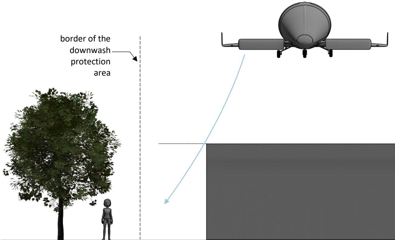
Figure C-2. Downwash protection area extended below the vertiport that is elevated

## PTS VPT-DSN.C.240 Protected side slope

(a) A vertiport should be provided with at least one protected side slope, rising at 45 degrees outward from the edge of the SA and extending to a distance of 10 m (see Figure C-3).

(b) The surface of a protected side slope should not be penetrated by obstacles.

![78608106f084bffb9c8013dcb3310462fa6559625b485c5b83a127bb41a894c2.jpg](https://aam-wiki.gksj.cc/uploads/images/gallery/2026-05/scaled-1680-/78608106f084bffb9c8013dcb3310462fa6559625b485c5b83a127bb41a894c2.jpg)  
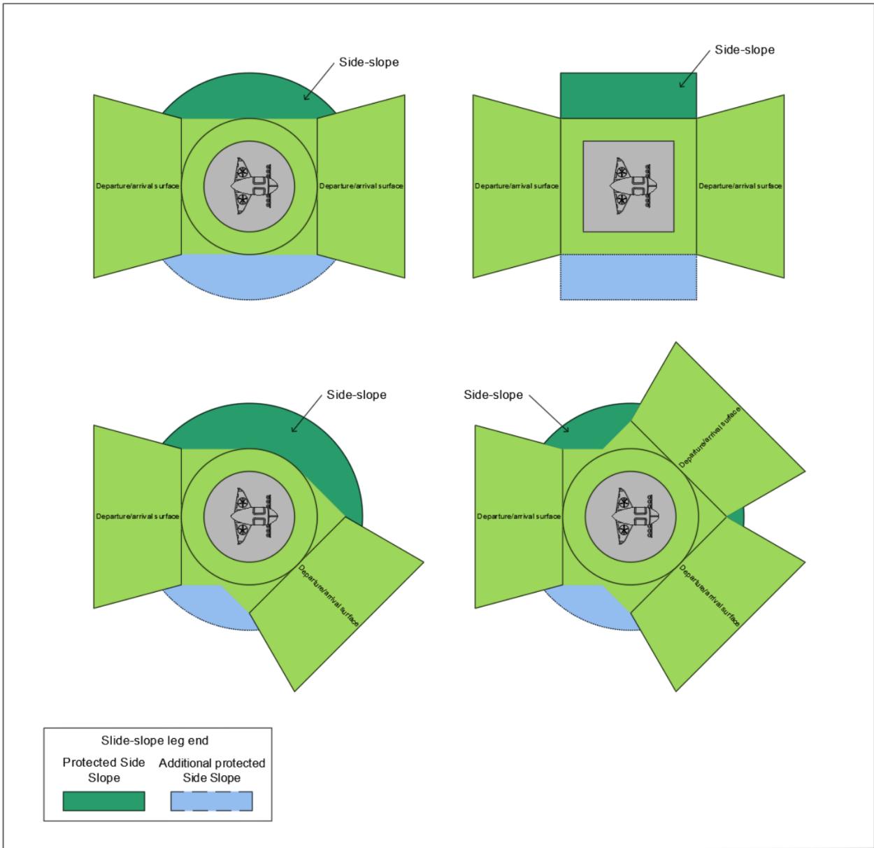
Figure C-3. FATO simple/complex SA and side slope protection

Note: These diagrams show a number of configurations of FATO/SA/side slopes. For a more complex arrival/departure arrangement which consists of: two surfaces that are not diametrically opposed; more than two surfaces; it can be seen that appropriate provisions are necessary to ensure that there are no obstacles between the FATO and/or SA and the arrival/departure surfaces.

## PTS VPT-DSN.C.250 VTOL-capable aircraft clearway

Note: The inclusion of detailed specifications for VTOL-capable aircraft clearways is not intended to imply that a clearway has to be provided.

(a) A VTOL-capable aircraft clearway should provide:

(1) an area free of obstacles, except for essential objects which because of their function are located on it, and of sufficient size and shape to ensure containment of the design VTOLcapable aircraft when it is accelerating in level flight, and close to the surface, to achieve its take-off safety speed; and

(2) when solid, a surface which: is contiguous and flush with the FATO and SA; is resistant to the effects of downwash; and is free of hazards if a forced landing is required; or

(3) when elevated, clearance above all obstacles.

(b) When a VTOL-capable aircraft clearway is provided, the inner edge should be located:

(1) at the outer edge of the SA; or

(2) when elevated, directly above, or directly below, the outer edge of the SA.

(c) The width of a VTOL-capable aircraft clearway should not be less than the width of the FATO and associated SA (see Figure C-1).

(d) When solid, the ground in a VTOL-capable aircraft clearway should not project above a plane having an overall upward slope of 3 per cent or having a local upward slope exceeding 5 per cent, the lower limit of this plane being a horizontal line which is located on the periphery of the FATO.

## PTS VPT-DSN.C.260 Touchdown and lift-of area (TLOF)

(a) A vertiport should be provided with at least one TLOF.

(b) A TLOF should be provided:

(i) whenever it is intended that the undercarriage of the VTOL-capable aircraft will touch down within a FATO, or stand, or lift off from a FATO or stand.

(ii) at least one TLOF should be provided at vertiport. That does not preclude when a VTOLcapable aircraft air taxi from a FATO to a stand, or from a stand to a FATO, it has to touch down on or lift off a taxiway to complete its movement.

(iii) where the taxiway is associated with an air taxi-route, the overall protection provided for the width of the surface, the surface loading and the width of the air taxi-route should be appropriate to that provided for a TLOF/FATO or TLOF/stand.

(c) A TLOF should:

(1) provide:

(i) an area free of obstacles and of sufficient size and shape to ensure containment of the undercarriage of the most demanding VTOL-capable aircraft the TLOF is intended to serve in accordance with the intended orientation;

(ii) a surface which:

(A) has sufficient bearing strength to accommodate the dynamic loads associated with the anticipated type of arrival of the VTOL-capable aircraft at the designated TLOF;

(B) is free of irregularities that would adversely affect the touchdown or lift-off of VTOL-capable aircraft;

(C) has sufficient friction to avoid skidding of VTOL-capable aircraft or slipping of persons;

(D) is resistant to the effects of downwash; and

(E) ensures effective drainage while having no adverse effect on the control or stability of a VTOL-capable aircraft during touchdown and lift-off, or when stationary; and

(2) be associated with a FATO, a portion of a taxiway or a stand.

(d) The minimum dimensions of a TLOF should be 0.83 D or the dimensions for the required procedure prescribed in the AFM of the VTOL-capable aircraft for which the TLOF is intended, whichever is greater.

(e) For a vertiport that is elevated, the minimum dimensions of a TLOF, when in a FATO, should be of sufficient size to contain a circle of diameter of at least 1 Design D. For a non-solid FATO, TLOF should be of sufficient size to permit servicing of the aircraft.

(f) When a TLOF is within a FATO it should be:

(1) centred on the FATO; or

(2) for an elongated FATO, centred on the longitudinal axis of the FATO.

(g) when a TLOF is within a VTOL-capable aircraft stand, centred on the stand.

(h) A TLOF should be provided with markings which clearly indicate the touchdown position and, by their form, any limitations on manoeuvring.

Note: When a TLOF in a FATO is larger than the minimum dimensions, the touchdown positioning marking (TDPM) (not the TLOF) may be offset while ensuring containment of the undercarriage within the TLOF and the VTOL-capable aircraft within the FATO.

(i) Where more than one TDPMs are provided, they should be placed to ensure containment of the undercarriage within the TLOF and the aircraft within the FATO.

Note: The efficacy of the rejected take-off or landing distance will be dependent upon the VTOLcapable aircraft being correctly positioned for take-off, or landing.

(j) Safety devices such as safety nets or safety shelves should be located around the edge of a vertiport that is elevated but should not exceed the height of the TLOF.

(k) Where provided, a safety net support assembly and its fixings to the vertiport primary structure should be designed to withstand the static load of the whole support structure, the netting system, and any attached appendages plus at least 125 kg load imposed on any section of the netting system. Where the safety shelving is provided, rather than netting, the construction and layout of the shelving should not promote any adverse wind flow issues over the FATO, while providing equivalent personnel safety benefits, and should be installed to the same minimum dimensions as the netting system, beyond the edge of the TLOF/FATO. It may also be further covered with netting to improve grab capabilities.

## PTS VPT-DSN.C.270 VTOL-capable aircraft taxiways and taxi-routes

Note 1: The specifications for ground taxi-routes and air taxi-routes are intended for the safety of simultaneous operations during the manoeuvring of VTOL-capable aircraft. The effect of wind velocity/turbulence induced by the downwash would need to be considered.

Note 2: The defined areas addressed in PTS:

(a) Taxiways may be associated either with air taxi-routes or ground taxi-routes.

(b) Ground taxi-routes are meant for use by ground taxiing of VTOL-capable aircraft under their own power or by means of ground movement equipment.

(c) Air taxi-routes are meant for use by air taxiing only.

## PTS VPT-DSN.C.280 VTOL-capable aircraft taxiways

Note 1: A VTOL-capable aircraft taxiway is intended to permit the surface movement of a VTOLcapable aircraft either under its own power or by means of ground movement equipment.

Note 2: A VTOL-capable aircraft taxiway should be designed to accommodate the undercarriage width (UCW) of the most demanding aircraft that it is intended to serve, as well as the width of the required ground movement equipment, whichever is greater.

Note 3: A VTOL-capable aircraft taxiway can be used by a VTOL-capable aircraft for air taxi if associated with a VTOL-capable aircraft air taxi-route.

Note 4: When a taxiway is intended for use by aeroplanes, helicopters and VTOL-capable aircraft, the provisions for aeroplane taxiways, taxiway strips; helicopter taxiways, taxi-routes; and VTOL-capable aircraft taxiways and taxi-routes will be taken into consideration and the more stringent requirements will be applied.

(a) A VTOL-capable aircraft taxiway should:

(1) provide:

(i) an area free of obstacles and of sufficient width to ensure containment, including taxiing deviations, of the undercarriage of the most demanding VTOL-capable aircraft, the taxiway is intended to serve;

(ii) a surface which:

(A) has bearing strength to accommodate the taxiing loads of the VTOL-capable

aircraft, that the taxiway is intended to serve;

(B) is free of irregularities that would adversely affect the ground taxiing or movement of VTOL-capable aircraft;

(C) where relevant, is resistant to the effects of downwash; and

(D) ensures effective drainage while having no adverse effect on the control or stability of a VTOL-capable aircraft when being manoeuvred under its own power or by means of ground movement equipment, or when stationary;

and

(2) be associated with a taxi-route.

(b) The minimum width of a VTOL-capable aircraft taxiway should be the lesser of:

(1) Two times the UCW of the most demanding VTOL-capable aircraft the taxiway is intended to serve; or

(2) a width meeting the requirements of PTS VPT-DSN.C.280 (a)(1)(i), above.

(c) The transverse slope of a VTOL-capable aircraft taxiway should not exceed 2 per cent and the longitudinal slope should not exceed 3 per cent.

(d) When defining the minimum distance between a ground taxiway and another ground taxiway, fixed or movable object, the following should be considered:

(1) 0.75 maximum width of the aircraft intending to use the ground taxiway when defining the distance between the ground taxiway centre line and a fixed or movable object; and

(2) 1.25 maximum width of the aircraft intending to use the ground taxiway when defining the separation between parallel ground taxiway centre lines.

(e) When defining the distance between ground taxiways used by large wingspan VTOL-capable aircraft, the separation distance between the centre line of a ground taxiway and the centre line of a parallel ground taxiway or an object should take into consideration a minimum wingtip clearance of at least 0.25 D.

## PTS VPT-DSN.C.290 VTOL-capable aircraft taxi routes

(a) A VTOL-capable aircraft taxi-route should provide:

(1) an area free of obstacles, except for essential objects which because of their function are located on ${ \mathrm { i t } } ,$ established for the movement of VTOL-capable aircraft, with sufficient width to ensure containment of the largest VTOL-capable aircraft the taxi-route is intended to serve;

(2) when solid, and where relevant, a surface which is resistant to the effects of rotor downwash and,

(i) when collocated with a taxiway:

(A) is contiguous and flush with the taxiway;

(B) does not present a hazard to operations; and

(C) ensures effective drainage; and

(ii) when not collocated with a taxiway, is free of hazards if a forced landing is required.

(b) No mobile object should be permitted on a taxi-route during VTOL-capable aircraft operations.

(c) When solid and collocated with a taxiway, the taxi-route should not exceed an upward transverse slope of 4 per cent outwards from the edge of the taxiway.

## PTS VPT-DSN.C.300 VTOL-capable aircraft ground taxi-routes

(a) A VTOL-capable aircraft ground taxi-route should have a minimum width of 1.5 times the overall width of the largest VTOL-capable aircraft it is intended to serve, and be centred on a taxiway (see Figure C-4).

Note: If the VTOL-capable aircraft designs allow for width changes (e.g. folding wings), a corresponding overall width should be considered for defining the taxi-route width.

(b) Essential objects located in a VTOL-capable aircraft ground taxi-route should not:

(1) be located at a distance of less than 50 cm outwards from the edge of the VTOL-capable aircraft ground taxiway; and

(2) penetrate a surface originating 50 cm outwards of the edge of the VTOL-capable aircraft taxiway and a height of 25 cm above the surface of the taxiway, and sloping upwards and outwards at a gradient of 5 per cent up to the outer edge of the ground taxi-route.

![cb6e2a62091855510b42b1c46b26286470f081323ce76d9b08ce5977e4d4e4c4.jpg](https://aam-wiki.gksj.cc/uploads/images/gallery/2026-05/scaled-1680-/cb6e2a62091855510b42b1c46b26286470f081323ce76d9b08ce5977e4d4e4c4.jpg)  
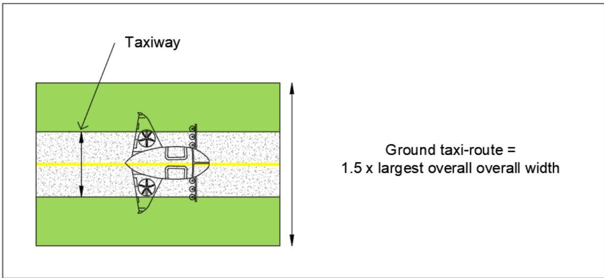
Figure C-4. VTOL-capable aircraft taxiway/ground taxi-route

## PTS VPT-DSN.C.310 VTOL-capable aircraft air taxi-routes

Note: A VTOL-capable aircraft air taxi-route is intended to permit the movement of a VTOL-capable aircraft above the surface at a height normally associated with ground effect and at ground speed less than 37 km/h (20 kt).

(a) A VTOL-capable aircraft air taxi-route should have a minimum width of twice the overall width of the largest VTOL-capable aircraft it is intended to serve.

Note: If the VTOL-capable aircraft designs allow for width changes (e.g. folding wings), a corresponding overall width should be considered for defining the taxi-route width.

(b) If collocated with a taxiway for the purpose of permitting both ground and air taxi operations (see Figure C-5):

(1) the VTOL-capable aircraft air taxi-route should be centred on the taxiway; and

(2) the essential objects located in the VTOL-capable aircraft air taxi-route should not:

(i) be located at a distance of less than 50 cm outwards from the edge of the VTOLcapable aircraft taxiway; and

(ii) penetrate a surface originating 50 cm outwards of the edge of the VTOL-capable aircraft taxiway and a height of 25 cm above the surface of the taxiway and sloping upwards and outwards at a gradient of 5 per cent.

(c) When not collocated with a taxiway, the slopes of the surface of an air taxi-route should not exceed the slope landing limitations of the VTOL-capable aircraft the taxi-route is intended to serve. In any event, the transverse slope should not exceed 10 per cent and the longitudinal slope should not exceed 7 per cent.

![c74dcd5b170c289afeab6c8602e678598b1a8282b7697ad38d8850e106a925c8.jpg](https://aam-wiki.gksj.cc/uploads/images/gallery/2026-05/scaled-1680-/c74dcd5b170c289afeab6c8602e678598b1a8282b7697ad38d8850e106a925c8.jpg)  
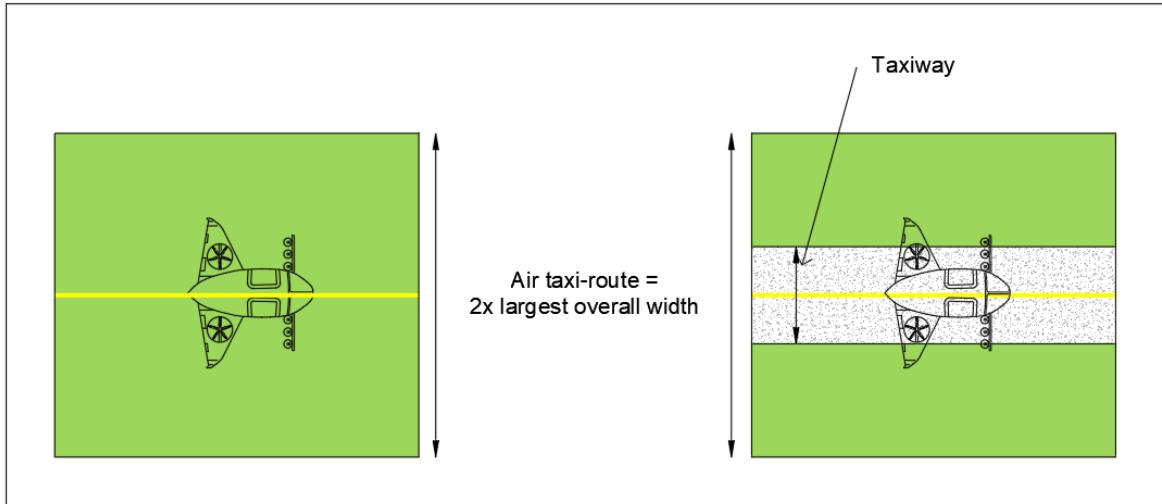
Figure C-5. VTOL-capable aircraft air taxi route and combined air taxi-route/taxiway

## PTS VPT-DSN.C.320 VTOL-capable aircraft stands

(a) Where provided, a VTOL-capable aircraft stands and aprons should permit the safe loading and off-loading of passengers and/or cargo, as well as the servicing of VTOL-capable aircraft without interfering with the apron traffic.

Note: A space for safe ground handling should be considered by planning the VTOL-capable aircraft stand design. In the case of a geometry-based stand, where appropriate, a tail clearance should be also provided (see Figure C-7).

(b) A VTOL-capable aircraft stand should:

(1) provide an area and its associated volume free of obstacles and of sufficient size and shape to ensure containment of every part of the largest VTOL-capable aircraft the stand is intended to serve when it is being positioned within the stand;

(2) provide a surface which:

(i) is resistant to the effects of downwash, where required;

(ii) is free of irregularities that would adversely affect the manoeuvring of VTOLcapable aircraft;

(iii) has bearing strength of static aircraft loads, loads of people and ground movement and handling equipment, intended to be used or, if collocated with TLOF, dynamic loads should be considered;

(iv) has sufficient friction to avoid skidding of VTOL-capable aircraft or slipping of persons; and

(v) ensures effective drainage while having no adverse effect on the control or stability of a VTOL-capable aircraft when being manoeuvred under its own power, when being moved by means of ground movement equipment, or when stationary; and

(3) be associated with a protection area.

Note: It is not considered good practice to locate VTOL-capable aircraft stands under a flight path, due to possible downwash and depending on the local conditions, obstacle environment, etc. The extended flight path could go along the vertiport; see the following example in Figure C-6.

![e31f9e0d4851595a03e8672b0afbd16d3ff2ca883828a9a606dcebe6a758fba9.jpg](https://aam-wiki.gksj.cc/uploads/images/gallery/2026-05/scaled-1680-/e31f9e0d4851595a03e8672b0afbd16d3ff2ca883828a9a606dcebe6a758fba9.jpg)  
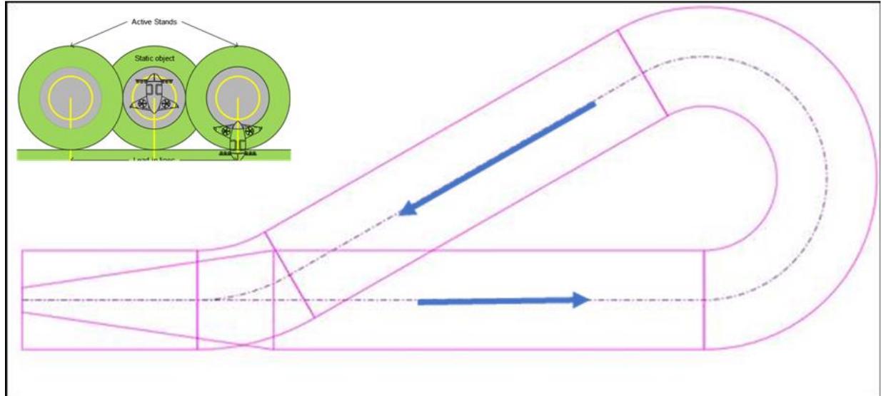
Figure C-6. Example of not providing parking stands under a flight path

Note: When determining the VTOL-capable aircraft stand and apron layout, the vertiport designer and/or operator should take into consideration various designs of the aircraft that the vertiport intends to serve. The configurations of VTOL-capable aircraft vary significantly (e.g. a multi-copter, a winged aircraft, etc.). As a result, it proved to be challenging to introduce a single, unified design of a VTOL-capable aircraft stand, based on the D-value, as it is commonly done in today’s helicopter world.

Furthermore, certain VTOL-capable aircraft can execute a power-in/push-back type manoeuvre under their own power or using a tug avoiding the need for hover turns, which resembles an aeroplane operation at an aerodrome.

Hence, a concept of a ‘vertiport apron’ and a ‘geometry-based stand’ are introduced in addition to conventional stands, originating from aerodrome design rules (namely, ADR.DSN.E.350 Size of aprons).

(d) VTOL-capable aircraft stands and the vertiport apron layout should be designed based on the geometry, ground movement and servicing requirements of a VTOL-capable aircraft intended to be served, taking into consideration the following factors:

(1) the size and manoeuvrability characteristics of the aircraft intending to use the VTOLcapable aircraft stand;

(2) clearance requirements;

(3) type of ingress and egress to the VTOL-capable aircraft stand;

(4) vertiport layout;

(5) VTOL-capable aircraft ground equipment and servicing requirements;

(6) taxiway access;

(7) intended use of the VTOL-capable aircraft stand (such a turning or taxi-through).

Note: Stands designed for turning or associated with a TLOF should be defined and sized based on the D-value considerations.

## D-value-based VTOL-capable aircraft stand

(e) When the VTOL-capable aircraft stand design is based on D-value, the minimum dimensions should be:

(1) a circle of diameter of 1.2 D of the largest VTOL-capable aircraft the stand is intended to serve; or

(2) when there is a limitation on manoeuvring and positioning, of sufficient width to meet the requirement of PTS VPT-DSN.C.320(b)(1) above, but not less than 1.2 times overall width of largest VTOL-capable aircraft the stand is intended to serve.

(f) A D-value-based VTOL-capable aircraft stand should be surrounded by a protection area which need not be solid.

Note 1: For a VTOL-capable aircraft stand intended to be used for taxi-through only, a width less than 1.2 D but which provides containment and still permits all required functions of a stand to be performed, might be used in accordance with PTS VPT-DSN.C.320(a), above.

Note 2: Each stand should be provided with positioning markings to clearly indicate where the VTOLcapable aircraft is to be positioned and, by their form, any limitations on manoeuvring.

## Geometry-based VTOL-capable aircraft stands

(g) For a VTOL-capable aircraft that enters/exits the stand with surface movement either under its own power or by means of ground movement equipment, where practical, stands may be designed in accordance with the geometry of the aircraft, following the aerodrome apron concept.

(h) The minimum dimension of a single geometry-based stand should rely on the geometry and performance of the VTOL-capable aircraft intending to use the geometry-based stand and provide the following minimum clearances between an aircraft entering or exiting the stand and any adjacent building and aircraft of another stand:

<table><tr><td rowspan=1 colspan=1>VTOL-capable aircraft width</td><td rowspan=1 colspan=1>Clearance(see Figure C-7)</td></tr><tr><td rowspan=1 colspan=1>Up to but not including 24 m</td><td rowspan=1 colspan=1>3m</td></tr><tr><td rowspan=1 colspan=1>24 m up to but not including 36 m</td><td rowspan=1 colspan=1>4.5m</td></tr><tr><td rowspan=1 colspan=1>36 m up to but not including 80 m</td><td rowspan=1 colspan=1>7.5m</td></tr></table>

(i) The minimum nose (VTOL-capable aircraft front point) to buildings clearance on geometrybased stands and/or the minimum side clearance between a VTOL-capable aircraft entering or exiting the stand and any adjacent building may be reduced to 2 m, if a safety assessment indicates that it would not adversely affect the safety of operations of a VTOL-capable aircraft (e.g. by demonstrating the accuracy of ground movement equipment used).

Note 1: The wingtip clearance to objects and neighbouring aircraft should be at least 3 m; however, the wingtip clearances of neighbouring aircraft may fully overlap, in case one is stationary.

Note 2: The minimum wingtip clearance of 3 m assumes that there are no moving parts that extend beyond the wingtip (e.g. open rotors at the tip of the wing) while entering or exiting the stand.

Note 3: With the minimum clearance ensured as per the table above, the geometry-based stand does not require an additional protection area surrounding it.

![c01b660174534b7bf989411c35a5671d329e2eeabd10b53abe11cfd4ae9e8d64.jpg](https://aam-wiki.gksj.cc/uploads/images/gallery/2026-05/scaled-1680-/c01b660174534b7bf989411c35a5671d329e2eeabd10b53abe11cfd4ae9e8d64.jpg)  
Figure C-7. VTOL-capable aircraft stand with a protection area based on VTOL geometry showing unshrouded rotors not turning

![a3ae21f952d07289d2ad440810a0eb6219b505b1dbf39483ede01f61c9cf7426.jpg](https://aam-wiki.gksj.cc/uploads/images/gallery/2026-05/scaled-1680-/a3ae21f952d07289d2ad440810a0eb6219b505b1dbf39483ede01f61c9cf7426.jpg)  
Figure C-8. VTOL-capable aircraft stands with a protection area

## PTS VPT-DSN.C.330 VTOL-capable aircraft stand protection area

(a) A protection area should be provided when the VTOL-capable aircraft stand is designed in accordance with the D-value-based VTOL-capable aircraft stand principles described above.

(b) The protection area should provide:

(1) an area free of obstacles, except for essential objects which because of their function are located on it; and

(2) when solid, a surface which is contiguous and flush with the stand; where relevant, is resistant to the effects of downwash, and ensures effective drainage.

(c) When associated with a stand designed for turning, the protection area should extend outwards from the periphery of the stand for a distance of 0.4 D or rely on turning circle data provided in the AFM of VTOL-capable aircraft intending to use the stand (see Figure C-9).

(d) When associated with a stand designed for taxi-through, the minimum width of the stand and protection area should not be less than the width of the associated taxi-route (see Figure C-10 and Figure C-11).

(e) When associated with a stand designed for non-simultaneous use (see Figure C-12 and Figure C-13):

(1) the protection area of adjacent stands may overlap but should not be less than the required protection area for the larger of the adjacent stands; and

(2) the adjacent non-active stand may contain a static object, but it should be wholly within the boundary of the stand.

Note: To ensure that only one of the adjacent stands is active at a time, the instruction provided to pilots should make clear that a limitation on the use of the stands is in force.

(f) No mobile object should be permitted in a protection area during VTOL-capable aircraft movement, unless the object is used to support the movement of the VTOL-capable aircraft (e.g. a towing vehicle).

(g) Essential objects located within the protection area should not:

(1) if located at a distance of less than 0.75 D from the centre of the VTOL-capable aircraft stand, penetrate a surface at a height of 5 cm above the surface of the central zone;

(2) if located at a distance of 0.75 D or more from the centre of the VTOL-capable aircraft stand, penetrate a surface at a height of 25 cm above the plane of the central zone and sloping upwards and outwards at a gradient of 5 per cent.

(h) When solid, the slope of a protection area should not exceed an upward slope of 4 per cent outwards from the edge of the stand.

![1ad36364be13db137bcecdbc03ee4eadedbd323c906efa0f6a9fec5c14352c1e.jpg](https://aam-wiki.gksj.cc/uploads/images/gallery/2026-05/scaled-1680-/1ad36364be13db137bcecdbc03ee4eadedbd323c906efa0f6a9fec5c14352c1e.jpg)

Figure C-9. Turning VTOL-capable aircraft stands (with air taxi-routes) — simultaneous use  
![2089e6fb05efbf9ce77405fec54607e31f340337604c0c7e2a67f51034f0a5c1.jpg](https://aam-wiki.gksj.cc/uploads/images/gallery/2026-05/scaled-1680-/2089e6fb05efbf9ce77405fec54607e31f340337604c0c7e2a67f51034f0a5c1.jpg)  
Figure C-10. Ground taxi-through stands (with taxiway/ground taxi-route) — simultaneous use

![cfd85cdf4af6ba890f6111311ff92946485eaa17ef75e27c8d71f9eac948f9a6.jpg](https://aam-wiki.gksj.cc/uploads/images/gallery/2026-05/scaled-1680-/cfd85cdf4af6ba890f6111311ff92946485eaa17ef75e27c8d71f9eac948f9a6.jpg)  
Figure C-11. Air taxi-through stands (with air taxi-route) — simultaneous use

![a3620491fad00e59002811245abf914853f8736d24dc7568ee33b35d90391b6c.jpg](https://aam-wiki.gksj.cc/uploads/images/gallery/2026-05/scaled-1680-/a3620491fad00e59002811245abf914853f8736d24dc7568ee33b35d90391b6c.jpg)  
Figure C-12. Turning stands (with air taxi-routes) — non-simultaneous use — outer stands active

![e8149d597132102f6149bbdf902a9440f81c715c0fef05dde0d5ddd77d8feeb4.jpg](https://aam-wiki.gksj.cc/uploads/images/gallery/2026-05/scaled-1680-/e8149d597132102f6149bbdf902a9440f81c715c0fef05dde0d5ddd77d8feeb4.jpg)  
Figure C-13. Turning stands (with air taxi-route) — non-simultaneous use — inner stand active

## PTS VPT-DSN.C.340 Location of a final-approach and take-off area (FATO) in relation to another FATO

(a) When determining the distance between two FATOs, a safety assessment should indicate that this would not adversely affect the safety of operations of a VTOL-capable aircraft.

(b) The safety assessment should take into consideration, at least the following aspects:

(1) type of operation;

(2) orientation of departure and approach flight path;

(3) balked landing procedure;

(4) the downwash data (provided in AFM);

(5) ensuring that SAs do not overlap.

Note 1: A 60-m separation distance between two FATOs has been recognised as a reference for simultaneous helicopter landings and take-offs where the courses to be flown do not conflict and where the MTOW of the helicopter does not exceed 3 175 kg. This distance can be used as a reference for conducting a safety assessment to determine whether the distance for VTOL-capable aircraft should be adapted.

Note 2: When there is a need to adapt a rectangular area, such as already existing runway type FATO or the runway at aerodrome, for simultaneous or quasi-simultaneous and close in space operations of VTOL-capable aircraft, following the assumption that no more than one VTOL-capable aircraft will be in the FATO at the same time, the principle of building blocks and encapsulation should be applied. The existing rectangular area has to be replaced by several FATOs in close proximity. Whether the operations can be simultaneous or not will depend on the separation of the FATOs in close proximity according to PTS VPT-DSN.C.340 (b).

## PTS VPT-DSN.C.350 Location of a final-approach and take-off area (FATO) in relation to an aerodrome runway or taxiway

(a) Where a FATO is located near a runway or taxiway and where simultaneous operations are planned, the separation distance between the edge of a runway or taxiway and the edge of a FATO should not be less than the appropriate dimension in Table C-2.

(b) A FATO should not be located:

(1) near taxiway intersections or holding points where jet engine efflux is likely to cause high turbulence; or

(2) near areas where aeroplane vortex wake generation is likely to exist.

<table><tr><td rowspan=1 colspan=1>If aeroplane mass and/or VTOL-capable aircraftmass are</td><td rowspan=1 colspan=1> Distance between FATO edge and runway edge ortaxiway edge</td></tr><tr><td rowspan=1 colspan=1>up to but not including 3 175 kg</td><td rowspan=1 colspan=1>60m</td></tr><tr><td rowspan=1 colspan=1>3 175 kg up to but not including 5 760 kg</td><td rowspan=1 colspan=1>120m</td></tr><tr><td rowspan=1 colspan=1>5 760 kg up to but not including 100 000 kg</td><td rowspan=1 colspan=1>180m</td></tr><tr><td rowspan=1 colspan=2>100 000 kg and over                                                                250mNote: The values specified in this table are primarily intended to mitigate risks of wake turbulence encounters. In addition to this table, when positioning a FATO intended to be used simultaneously with a nearbyrunway or taxiway, attention should be given to other CS ADR-DSN requirements such as the minimumrunway strip width. Local environment should be taken into account when setting the separationbetween the FATO and nearby infrastructure elements to ensure the safety of simultaneous operations.</td></tr></table>

Table C-2. FATO minimum separation distance

# CHAPTER D — OBSTACLE ENVIRONMENT

## PTS VPT-DSN.D.400 Applicability

## Rationale

1. Chapter D is composed of two subparts, Subpart 1 for OLSs, and Subpart 2 for OFV. The limitation surface should be such that the population of VTOL-capable aircraft can achieve conformance in the case of a failure or failures that have a severity of less than catastrophic. There are two main issues: the maximum slope that can be achieved for the population of vehicles; and the type of take-off and landing profiles that are envisaged.

2. The Chapter is providing a minimum requirement to be set in the design of vertiport.

3. The surfaces require a clear area surrounding the vertiport. Because the majority of vertiports will be sited in urban areas and the environment will be rich in obstacles, it is likely that the take-off and landing profiles will have to perform a vertical element and the clearways (if necessary and provided) and take-off, climb and landing surfaces will be elevated. The vertical transit, from/to the vertiport surface, will be conditioned by the type of operation that is envisaged. The ascent/descent path for operations with a pilot should be pilot’s field of view (FOV) to conduct a take-off/landing/reject — this is likely to require a sideways or backwards element, with the associated human error margins.

4. More guidance on the separation between the ascent/descent path and transitional surface is provided in ICAO Document 9261, Heliport Manual, Appendix A to Chapter 4 — tailored to the error margins associated with the type of operation.

The objectives of the technical specifications in this Chapter are to describe the airspace around vertiports to permit intended VTOL-capable aircraft operations to be conducted safely and to prevent vertiports from becoming unusable by the growth of obstacles around them. This is achieved by establishing a series of OLSs and OFVs that define the limits to which objects may project into the airspace.

Note. This Chapter contains two separate Subparts. Subpart 1 refers to the conventional Obstacle limitation surfaces (OLS), provided in Annex 14, Volume II, Heliports, Chapter 4 and in ICAO Document 9261, Heliport Manual. Subpart 2 refers to the concept of the ‘obstacle-free volume’ established at the vertiport.

# CHAPTER D, SUBPART 1 — OBSTACLE LIMITATION SURFACES

## PTS VPT-DSN.D.405 General

(a) In order to safeguard a VTOL-capable aircraft during its approach to the FATO and in its climb after take-off, an approach surface and a take-off climb surface through which no obstacle is permitted to project is established for each approach and take-off climb path designated as serving the FATO.

(b) The minimum dimensions required for such surfaces will vary considerably and depend on the:

(1) VTOL-capable aircraft size, its climb gradient, particularly for critical failure for performance (CFP), its approach speed and rate of descent on the final approach, and its controllability at such speeds; and

(2) conditions under which the approaches/departures are made.

(c) In many instances, the presence of permanent, high obstacles such as radio masts, buildings or areas of high ground may preclude the provision of the required take-off climb/approach surfaces for a straight take-off climb or approach, whereas the criteria required for the surfaces would be feasible if:

(1) a curved flight path avoiding the obstacles is established; or

(2) the origin of the approach or take-off climb surfaces is elevated with or without a turn.

Note: The slope design categories depicted in Table D-1 represent minimum design slope angles and not operational slopes. Consultation with VTOL-capable aircraft operators will help to determine the appropriate slope category according to the vertiport environment and the VTOL-capable aircraft the vertiport is intended to serve.

(d) In the case of an approach or take-off climb surface involving a turn:

(1) when selecting a curved flight path, the performance and handling characteristics of the VTOL-capable aircraft, eluding undue discomfort to the passengers and minimising noise nuisance by avoiding the overflying of populated areas, should be considered (see Figure D-1);

(2) the lateral and vertical surfaces should be the same as those for a straight approach surface;

(3) more than one curved portion, separated by a straight section of more than 150 m, are permitted;

(4) The sum of the radius of arc defining the centre line of the approach surface and the length of the straight portion originating at the inner edge should not be less than 575 m. Any combination of curve and straight portion may be established using the following formula:

## S+R ≥575 m and R ≥ 270 m where S = 305 m

where S is the length of the straight portion and R is the radius of turn.

Note: Because VTOL-capable aircraft take-off performance is reduced in a turn, a straight portion along the take-off climb surface prior to the start of the curve should be considered. This will permit an acceleration with CFP to achieve a stable climb attitude and speed before a turn is initiated. Limits on bank angle and degradation of turns on performance in accordance with the AFM should be noted and applied to the design VTOL-capable aircraft.

(5) In the case of an approach and departure surface involving turns, the surface should be a complex surface containing the horizontal normals to its centre line and the slope of the centre line should be the same as that for a straight approach surface.

(6) When a VTOL-capable aircraft is capable of performing turns with smaller radius and straight portions, the minimum radius of turns and the length of the straight portion may be reduced, if the safety assessment determines that it would not adversely affect the safety or significantly affect the regularity of operations of VTOL-capable aircraft at vertiport. The safety assessment should consider the turn values and limitations on bank angles and CFP degradation provided in the AFM of the most demanding VTOL-capable aircraft that the vertiport is intended to serve.

Further guidance is given in EASA SC-VTOL.2115.

![49b8fd3af4aef39d1387726cbe6d8fd500fb84cb657524a54b19f6b1cf34acb6.jpg](https://aam-wiki.gksj.cc/uploads/images/gallery/2026-05/scaled-1680-/49b8fd3af4aef39d1387726cbe6d8fd500fb84cb657524a54b19f6b1cf34acb6.jpg)  
Figure D-1. Curved approach and take-off climb surface for all FATOs

## Blending the spaces between the approach or take-off climb surface and SA

(e) The reference circle is an inscribed circle inside the FATO/SA that is used for orienting the approach/take-off and climb surface, transition area and VTOL-capable aircraft clearway.

(f) Areas between the inner edge of the approach or take-off climb surface and the SA, if any, should have the same characteristics as the SA, since it would be unacceptable for such areas to have characteristics that were below the standards of either of the adjoining surfaces.

Note: Figure D-2 to Figure D-5 illustrate such areas by shading the relevant portions, but these are, of necessity, shown only for the basic configurations of FATO and SA and are not drawn to scale. However, the planned direction of the approach surface may not be located in line with, or at a convenient 45° to, the centre line of the FATO. Furthermore, the FATO, and thus the SA, may be of irregular shape or be much larger than one which can only just accommodate a circle of the minimum specified dimensions.

![d774ce492718363060df24dbb1df98c4f11604d27de5cb48cd2b6b3cc3474fb4.jpg](https://aam-wiki.gksj.cc/uploads/images/gallery/2026-05/scaled-1680-/d774ce492718363060df24dbb1df98c4f11604d27de5cb48cd2b6b3cc3474fb4.jpg)

Figure D-2. Square FATO with reference circle and surfaces separated by 135⁰  
![e55da5a7d1e35b4b74fd6f86320087d2cdc37726d34419a228c7d8715e191e0f.jpg](https://aam-wiki.gksj.cc/uploads/images/gallery/2026-05/scaled-1680-/e55da5a7d1e35b4b74fd6f86320087d2cdc37726d34419a228c7d8715e191e0f.jpg)  
Figure D-3. Octagonal FATO with reference circle and diametrically opposed surfaces

(g) The issues involved with such deviations from the basic configurations are:

(1) where the inner edge should be located; and

(2) the shapes and sizes of the shaded areas may vary considerably.

(h) To identify the shaded areas, if any, it is necessary to consider their side edges as extending from the ends of the inner edge to points where they meet the tangent of the reference circle at right angles to the centre line of the surface. The shaded areas will then be bounded by these side edges, the inner edge and the edges of the SA.

(i) Where the FATO is elongated, there should be two reference circles within the SA, each located at the appropriate approach end of the SA (see Figure D-4).

![73736df4d9c1d88f3dee6077513e83c3edea6a9815da31370a52d853b3a11723.jpg](https://aam-wiki.gksj.cc/uploads/images/gallery/2026-05/scaled-1680-/73736df4d9c1d88f3dee6077513e83c3edea6a9815da31370a52d853b3a11723.jpg)  
Figure D-4. Rectangular FATO with two reference circles and surfaces separated by 135⁰

(j) Where a clearway has been established, the shaded area should be between the FATO/SA and clearway (see Figure D-5); the inner edge of the approach or take-off climb surface will abut the clearway.

![0d1805e4d60f0361fb988f58ff8c61a1ecc9bac6928485f97a50ae196935c561.jpg](https://aam-wiki.gksj.cc/uploads/images/gallery/2026-05/scaled-1680-/0d1805e4d60f0361fb988f58ff8c61a1ecc9bac6928485f97a50ae196935c561.jpg)  
Figure D-5. Rectangular FATO with two reference circles and helicopter clearway

## Number and separation of take-off and climb and approach surfaces

(k) Vertiport design and location should be such that downwind operations are avoided, crosswind operations are kept to a minimum, and balked landings can be carried out with the minimum change of direction.

(l) The vertiport should have at least two take-off and climb and approach surfaces with a recommend separation of at least 135⁰ (see Figure D-2) but ideally separated by 180⁰. Additional approach surfaces may be provided, the total number and orientation ensuring that the vertiport usability factor will be at least 95 per cent for the VTOL-capable aircraft the vertiport is intended to serve. These criteria should apply equally to vertiports at surface level or vertiports that are elevated.

(m) Where the prototype technical specifications above cannot be met, the separation may be decreased or the number of take-off and climb and approach surfaces reduced to one, if the safety assessment determines that it would not adversely affect the safety or significantly affect the regularity of operations of VTOL-capable aircraft at vertiport.

(n) When only a single approach and take-off climb surface is provided, a safety assessment should be undertaken considering, as a minimum, the following factors:

(1) the area/terrain over which the flight is being conducted;

(2) the obstacle environment surrounding the vertiport; and the availability of at least one protected side slope;

(3) the performance and operating limitations of VTOL-capable aircraft intending to use the vertiport; and

(4) the local meteorological conditions including the prevailing winds.

<table><tr><td rowspan=2 colspan=1> SURFACE AND DIMENSIONS</td><td rowspan=1 colspan=3>SLOPE DESIGN CATEGORIES</td></tr><tr><td rowspan=1 colspan=1>A</td><td rowspan=1 colspan=1>B</td><td rowspan=1 colspan=1>C</td></tr><tr><td rowspan=1 colspan=1>APPROACH AND TAKE-OFF CLIMBSURFACE:</td><td rowspan=1 colspan=1></td><td rowspan=1 colspan=1></td><td rowspan=1 colspan=1></td></tr><tr><td rowspan=1 colspan=1>Length of inner edge</td><td rowspan=1 colspan=1>Width of SA</td><td rowspan=1 colspan=1>Width of SA</td><td rowspan=1 colspan=1>Width of SA</td></tr><tr><td rowspan=1 colspan=1>Location of inner edge</td><td rowspan=1 colspan=1>SA boundary(Clearway boundary ifprovided)</td><td rowspan=1 colspan=1>SA boundary</td><td rowspan=1 colspan=1>SA boundary</td></tr><tr><td rowspan=1 colspan=1>Divergence: (1st and 2nd section)</td><td rowspan=1 colspan=1></td><td rowspan=1 colspan=1></td><td rowspan=1 colspan=1></td></tr><tr><td rowspan=1 colspan=1>Day use only</td><td rowspan=1 colspan=1>10%</td><td rowspan=1 colspan=1>10%</td><td rowspan=1 colspan=1>10%</td></tr><tr><td rowspan=1 colspan=1>Night use</td><td rowspan=1 colspan=1>15%</td><td rowspan=1 colspan=1>15%</td><td rowspan=1 colspan=1>15%</td></tr><tr><td rowspan=1 colspan=1>First section:</td><td rowspan=1 colspan=1></td><td rowspan=1 colspan=1></td><td rowspan=1 colspan=1></td></tr><tr><td rowspan=1 colspan=1>Length</td><td rowspan=1 colspan=1>3 386m</td><td rowspan=1 colspan=1>245m</td><td rowspan=1 colspan=1>1220m</td></tr><tr><td rowspan=1 colspan=1>Slope</td><td rowspan=1 colspan=1>4.5%(1:22.2)</td><td rowspan=1 colspan=1>8%(1:12.5)</td><td rowspan=1 colspan=1>12.5%(1:8)</td></tr><tr><td rowspan=1 colspan=1>Outer width</td><td rowspan=1 colspan=1>(b)</td><td rowspan=1 colspan=1>N/A</td><td rowspan=1 colspan=1>(b)</td></tr><tr><td rowspan=1 colspan=4>Second section:</td></tr><tr><td rowspan=1 colspan=1>Length</td><td rowspan=1 colspan=1>N/A</td><td rowspan=1 colspan=1>830m</td><td rowspan=1 colspan=1>N/A</td></tr><tr><td rowspan=1 colspan=1>Slope</td><td rowspan=1 colspan=1>N/A</td><td rowspan=1 colspan=1>16%(1:6.25)</td><td rowspan=1 colspan=1>N/A</td></tr></table>

<table><tr><td rowspan=2 colspan=1>SURFACE AND DIMENSIONS</td><td rowspan=1 colspan=3>SLOPE DESIGN CATEGORIES</td></tr><tr><td rowspan=1 colspan=1>A</td><td rowspan=1 colspan=1>B</td><td rowspan=1 colspan=1>C</td></tr><tr><td rowspan=1 colspan=1>Outer width</td><td rowspan=1 colspan=1>N/A</td><td rowspan=1 colspan=1>(b)</td><td rowspan=1 colspan=1>N/A</td></tr><tr><td rowspan=1 colspan=1>Total length from inner edge (a)</td><td rowspan=1 colspan=1>3386mc</td><td rowspan=1 colspan=1>1075mc</td><td rowspan=1 colspan=1>1220mc</td></tr><tr><td rowspan=1 colspan=1>TRANSITIONAL SURFACEd:</td><td rowspan=1 colspan=1></td><td rowspan=1 colspan=1></td><td rowspan=1 colspan=1></td></tr><tr><td rowspan=2 colspan=1>Slope:</td><td rowspan=1 colspan=1>50%</td><td rowspan=1 colspan=1>50%</td><td rowspan=1 colspan=1>50%</td></tr><tr><td rowspan=1 colspan=1>(1:2)</td><td rowspan=1 colspan=1>(1:2)</td><td rowspan=1 colspan=1>(1:2)</td></tr><tr><td rowspan=1 colspan=1>Height:</td><td rowspan=1 colspan=1>45 m</td><td rowspan=1 colspan=1>45m</td><td rowspan=1 colspan=1>45m</td></tr></table>

Table D-1. Dimensions and slopes of OLSs for all visual FATOs

## PTS VPT-DSN.D.410 Approach surface

## (a) Applicability

The purpose of the approach surface is to protect a VTOL-capable aircraft during the final approach to the FATO by defining the area that should be kept free from obstacles to protect a VTOL-capable aircraft in the final phase of the approach-to-land manoeuvre.

## (b) Description

An incline plane or a combination of planes or, when a turn is or turns are involved, a complex surface sloping upwards from the inner edge and centred on a line passing through the centre of the FATO.

![d0727eebba7656d55b470d95f6b53e8f383e185b160d2211d6982d265e951626.jpg](https://aam-wiki.gksj.cc/uploads/images/gallery/2026-05/scaled-1680-/d0727eebba7656d55b470d95f6b53e8f383e185b160d2211d6982d265e951626.jpg)  
Figure D-6. Generic approach/take-off climb surface

## (c) Characteristics

(1) The limits of an approach surface should comprise:

(i) an inner edge, horizontal and equal in length to the minimum specified width of the FATO plus the SA, perpendicular to the centre line of the approach surface and located at:

(A) for a runway-type FATO, the outer edge of the SA; or

(B) for other than a runway-type FATO, the outer edge of the reference circle;

(ii) two side edges originating at the ends of the inner edge and diverging uniformly at a specified rate from the vertical plane, containing the centre line of the FATO to a specified width and continuing thereafter at that width for the remaining length of the approach surface; and

(iii) an outer edge horizontal and perpendicular to the centre line of the approach surface at a specified height above the elevation of the FATO.

(2) The elevation of the inner edge should be the elevation of the SA at the point on the inner edge that is intersected by the centre line of the approach surface. When safety assessment determines that it would not adversely affect the safety or significantly affect the regularity of operations of VTOL-capable aircraft at vertiport, the origin of the inclined plane may be raised directly above the FATO.

(3) The slope(s) of the approach surface should be measured in the vertical plane containing the centre line of the surface.

(4) In the case of an approach surface involving a turn, the surface should be a complex surface containing the horizontal normals to its centre line and the slope of the centre line should be the same as that for a straight approach surface.

(5) Where a curved portion of an approach surface is provided, the sum of the radius of arc defining the centre line of the approach surface and the length of the straight portion originating at the inner edge should not be less than 575 m.

(6) Any variation in the direction of the centre line of an approach surface should be designed so as not to necessitate a turn radius less than 270 m.

Further guidance on elevating approach surface is provided in ICAO Document 9261, Heliport Manual.

## PTS VPT-DSN.D.415 Transitional surface

## (a) Objective

The objective of the transitional surface is to provide a protected airspace when vertical procedures include lateral transit. The transitional surface defines the limit of the area where obstacles are, or may be, located (i.e. buildings, structures or natural obstructions such as trees).

## (b) Applicability

Where appropriate, a transitional surface may be provided at VFR vertiports for the safety of VTOL-capable aircraft when vertical procedures with lateral transit are planned.

## (c) Description

A complex surface bounded by a lower and upper edge and sloping upwards and outwards from one to the other (see Figure D-7, Figure D-8 and Figure D-9).

![66eaa73b6672bc8740e1357a44ef7850c10da8fcd1ded73061f97a946fc2c60a.jpg](https://aam-wiki.gksj.cc/uploads/images/gallery/2026-05/scaled-1680-/66eaa73b6672bc8740e1357a44ef7850c10da8fcd1ded73061f97a946fc2c60a.jpg)  
Figure D-7. Transitional, backup and take-off climb surface

![82e20bc73371d6c6931a095c8a629d1fe06990252ca6d7bad4ff6727c82e04f6.jpg](https://aam-wiki.gksj.cc/uploads/images/gallery/2026-05/scaled-1680-/82e20bc73371d6c6931a095c8a629d1fe06990252ca6d7bad4ff6727c82e04f6.jpg)  
Figure D-8. Transitional, backup and approach surface

![6e06c5daed714bc3c6111606c3f7c94923fee92c453e4f822ed1da4610353d39.jpg](https://aam-wiki.gksj.cc/uploads/images/gallery/2026-05/scaled-1680-/6e06c5daed714bc3c6111606c3f7c94923fee92c453e4f822ed1da4610353d39.jpg)  
Figure D-9. Transitional surface

## (d) Characteristics

(1) The transitional surface should comprise:

(i) a lower edge beginning at the point where the approach, or take-off climb, surface and upper edge of the transitional surface are at the same height, then extending downwards and along the side of the approach surface, or take-off climb surface to the inner edge and from there:

(A) where provided, along the side of the clearway; then

(B) for a runway-type FATO, along the length of the side of the SA parallel to the centre line of the FATO; or

(C) for other than a runway-type FATO, along the tangent of the reference circle parallel, and equal in length, to its diameter; and

(ii) an upper edge located at 45 m above the FATO.

(2) The extended transitional surface and modified extended transitional surface should comprise:

(i) a lower edge beginning at the point where the approach surface, or take-off climb surface and upper edge of the transitional surface are at the same height, then extending downwards and along the side of the approach, or take-off climb, surface to the inner edge and from there:

(A) for the take-off climb along the length of the clearway to the inner edge; then

(B) directly down to, and connecting with, the outer edge of the SA (see Figure D-10);

(C) along the tangent of the reference circle until level with the back edge of the SA; then

(D) up and along the outer edge of the backup obstacle surface until reaching the upper edge;

(ii) an upper edge located at 45 m (150 ft) plus the elevation of the OLS origin/clearway.

![717c7a0486beadb79da99856a4d3dbaf83a8c42d25ec69cddef25e0b59522006.jpg](https://aam-wiki.gksj.cc/uploads/images/gallery/2026-05/scaled-1680-/717c7a0486beadb79da99856a4d3dbaf83a8c42d25ec69cddef25e0b59522006.jpg)  
Figure D-10. Transitional surface (showing the drop from clearway to SA)

(3) The slope of the transitional surface should be measured in a vertical plane at right angles to the centre line of the FATO and should be:

(i) for a transitional surface and extended transitional surface 50 per cent (1:2) (see Table D-1); or

(ii) for a modified extended transitional surface 1:1 (45°).

![433a1c3c8c2932662b63d13b4e0a5a28d37875abb4005ad95455e847a1d87956.jpg](https://aam-wiki.gksj.cc/uploads/images/gallery/2026-05/scaled-1680-/433a1c3c8c2932662b63d13b4e0a5a28d37875abb4005ad95455e847a1d87956.jpg)  
Figure D-11. Elevated OLS and transitional surface

Note 1: The modified extended transitional surface can be regarded as an extension to the protected side slope (see PTS VPT-DSN.C.240).

Note 2: Further guidance on elevating an approach and take-off climb surface is provided in ICAO Document 9261, Heliport Manual.

Note 3. Further guidance on how to protect airspace during the backup procedure of VTOLcapable aircraft is provided in the Air OPS Regulation, in ICAO Document 9261, Heliport Manual, and in the AFM.

Note 4: Additional clarification on the transitional surface:

Principles of the basic transitional surface:

The upper edge is 45 m above the OLS origin.

The upper and lower edges commence at a point adjacent to the back edge of the SA.

The lower edge and upper edge meet on the side of the OLS.

The lower edge tracks along the tangent to the reference circle, parallel with the centre line of the FATO, to the inner edge of the OLS and then along the OLS until meeting the upper edge.

The slope of the transitional surface is 1:2.

Principles of the extended transitional surface (in addition to those of the basic transitional surface):

The upper edge is extended upwards by the elevation of the OLS origin.

The rear of the extended surface is attached to the outer edge of the backup surface.

The lower edge rises directly from the outer edge of the SA to the inner edge of the clearway or OLS.

Principles of the modified extended transitional surface (in addition to/modification of those of the extended):

The slope of the modified extended transitional surface is 1:1.

The characteristics of the take-off climb surface are provided in PTS VPT-DSN.D.420 and in Table D-1.

The characteristics of the extended clearway for the take-off climb:

The clearway is elevated to a level that permits clearance of obstacles in the take-off climb.

The width of the clearway is extended on each side, by twice its elevation, to meet the surface of the extended transitional surface.

The characteristics of the modified extended clearway for take-off climb (in addition to/modification of those of the basic clearway):

The width of the clearway is extended on each side, by its elevation, to meet the surface of the extended modified transitional surface.

The origin of the extended the take-off climb surface:

The inner edge of the take-off climb surface is at the outer edge of the clearway.

The width of the inner edge of the take-off climb surface is the width of the clearway.

The characteristics of the approach surface are provided PTS VPT-DSN.D.410 and in Table D-1:

The origin of the approach surface is elevated to a level that permits clearance of obstacles in the approach.

The inner edge of the approach surface is extended on each side by:

twice the amount of elevation, to meet the surface of the extended transitional surface; or

the amount of elevation, to meet the surface of the extended modified transitional surface.

The backup procedure may be of three types:

pure backup procedure: it does not need lateral protection;

limited lateral procedure: the required lateral protection is ensured by a modified extended transitional surface; and

full lateral procedure: the required lateral protection is ensured by an extended transitional surface.

## PTS VPT-DSN.D.420 Take-off climb surface

## (a) Applicability

The purpose of the take-off climb surface is to protect a VTOL-capable aircraft on take-off and during climb-out.

## (b) Description

An inclined plane, a combination of planes or, when a turn is or turns are involved, a complex surface, sloping upwards from the end of the SA, or of the clearway, when it is provided, and centred on a line passing through the centre of the FATO.

## (c) Characteristics

(1) The limits of a take-off climb surface should comprise (see Figure D-6):

(i) an inner edge horizontal and equal in length to the minimum specified width of the FATO plus the SA, perpendicular to the centre line of the take-off climb surface and located at:

(A) for a runway-type FATO, the outer edge of the SA;

(B) for other than a runway-type FATO, the tangent of the outer edge of the reference circle; or

(C) the outer edge of the clearway;

(ii) two side edges originating at the ends of the inner edge and diverging uniformly at a specified rate from the vertical plane, containing the centre line of the FATO to a specified final width and continuing thereafter at that width for the remaining length of the take-off climb surface; and

(iii) an outer edge horizontal and perpendicular to the centre line of the take-off climb surface and at a specified height above the elevation of the FATO.

(2) The elevation of the inner edge should be the elevation of the SA at the point on the inner edge that is intersected by the centre line of the take-off climb surface except that when a helicopter clearway is provided, the elevation should be equal to the highest point on the ground on the centre line of the helicopter clearway (for a take-off climb surface with an elevated origin).

(3) In the case of a take-off climb surface involving a turn, the surface should not contain more than one curved portion.

(4) The slope should be measured in the vertical plane containing the centre line of the surface.

Further guidance on elevating take-off approach surface is provided in ICAO Document 9261, Heliport Manual.

## PTS VPT-DSN.D.425 Application of obstacle limitation surfaces

(a) The obstacle limitation requirements for vertiports at surface level and vertiports that are elevated will be the same. For vertiports that are elevated, the specified surfaces should be defined relative to the horizontal plane at the elevation of the FATO.

(b) The following OLSs should be established for a FATO at a vertiport:

(i) take-off climb surface;

(ii) approach surface; and

(iii) where provided (see PTS VPT-DSN.D.415, above), transitional surface.

(c) The dimensions of the take-off climb/approach surfaces should be considered in two parts.

(1) In the first part, the lateral edges of the surface diverge from the direction of the centre line by 10 per cent on each side for daylight operations and 15 per cent on each side for night operations (see Figures D-12). The divergence should extend until the overall width of the surface has reached, for daylight operations 7 times D-value, and for night operations 10 times D-value. The increase in divergence and width at night is to allow for lack of visual references.

(2) In the second part, the width of the surface should remain constant at the 7 D or 10 Dvalues, as appropriate. The surface ends where the surface slope reaches 152 m (500 ft) above FATO elevation.

![d21e5158285e295e019cb39bc01f110d5fea7da23978762cbf71f5dc9c958d52.jpg](https://aam-wiki.gksj.cc/uploads/images/gallery/2026-05/scaled-1680-/d21e5158285e295e019cb39bc01f110d5fea7da23978762cbf71f5dc9c958d52.jpg)  
Figure D-12. Take-off climb/approach widths (schematic)

Further guidance for vertiports with elevated origin of an approach and take-off climb surfaces is provided in ICAO Document 9261, Heliport Manual, and in the AFM.

Further guidance on how to protect airspace and surrounding during the backup procedure of VTOLcapable aircraft is provided in the Air OPS Regulation, in ICAO Document 9261, Heliport Manual, and in the AFM.

## PTS VPT-DSN.D.430 Obstacle limitation requirements

Note 1: The requirements for OLSs are specified on the basis of the intended use of a FATO, i.e. approach manoeuvre to hover or landing, or take-off manoeuvre and type of approach, and are intended to be applied when such use is made of the FATO. In cases where operations are conducted to or from both directions of a FATO, then the function of certain surfaces may be nullified because of more stringent requirements of another lower surface.

(a) The slopes of the OLSs should not be greater than, and their other dimensions not less than, those specified in Table D-1 and should be located as shown in Figure D-1 to Figure D-12.

(b) For vertiports that have an approach/take-off climb surface with a 4.5 per cent slope design, objects can be permitted to penetrate the OLS, if after a safety assessment, it is determined that the object would not adversely affect the safety or significantly affect the regularity of operations of VTOL-capable aircraft.

(c) New objects or extensions of existing objects should not be permitted above the approach or take-off climb surfaces except when shielded by an existing immovable object or when after a safety assessment, it is determined that the object would not adversely affect the safety or significantly affect the regularity of operations of VTOL-capable aircraft.

(d) Existing objects above the approach and take off climb surfaces should, as far as practicable, be removed except when the object is shielded by an existing immovable object or when after a safety assessment, it is determined that the object would not adversely affect the safety or significantly affect the regularity of operations of VTOL-capable aircraft.

Note 2: Once such surfaces are established, it may become necessary to remove existing obstacles which project through the surface and restrict the erection of new structures which would become obstacles. Mobile or temporary objects such as cranes, lorries, boats and trains may be obstacles at times, in which case it might be necessary to delay VTOL-capable aircraft operations until the obstacle is moved clear, or temporary operational limits are temporarily established (e.g. reduction of take-off mass). For longer lasting temporary obstacles, supplementary take-off climb or approach surfaces might have to be developed and promulgated.

## CHAPTER D, SUBPART 2 — OBSTACLE-FREE VOLUME

## PTS VPT-DSN.D.440 General

The objective of the obstacle-free volume (OFV) is to provide protection above vertiports to facilitate the introduction of vertiports in congested areas and an obstacle populated environment for VTOLcapable aircraft. The corresponding procedure is designated as ‘vertical take-off and landing’. Due to the reduced footprint and vertical nature of the take-off and landing, synthetic cues may have to be used to guide the aircraft.

## PTS VPT-DSN.D.445 Generic volume

## (a) Characteristics

(1) The obstacle-free volume is derived from the vertical take-off and landing procedure volume, provided in the AFM, expressed in terms of the parameters listed in Table D-2 and depicted in Figure D-13 and Figure D-14:

<table><tr><td rowspan=1 colspan=1>Parameter</td><td rowspan=1 colspan=1>Short description</td></tr><tr><td rowspan=1 colspan=1> $\mathsf { h } _ { 1 }$ </td><td rowspan=1 colspan=1>Low hover height</td></tr><tr><td rowspan=1 colspan=1> $\mathsf { h } _ { 2 }$ </td><td rowspan=1 colspan=1>High hover height</td></tr><tr><td rowspan=1 colspan=1> $\mathsf { T O } _ { \mathsf { w i d t h } }$ </td><td rowspan=1 colspan=1>Width at $\mathsf { h } _ { 2 }$ </td></tr><tr><td rowspan=1 colspan=1> $\mathsf { T O } _ { \mathsf { f r o n t } }$ </td><td rowspan=1 colspan=1>Front distance at $\mathsf { h } _ { 2 }$ </td></tr><tr><td rowspan=1 colspan=1> $\mathsf { T O } _ { \mathsf { b a c k } }$ </td><td rowspan=1 colspan=1>Back distance at $\mathsf { h } _ { 2 }$ </td></tr><tr><td rowspan=1 colspan=1> $\mathsf { F A T O } _ { \mathsf { w i d t h } }$ </td><td rowspan=1 colspan=1>Width of the FATO</td></tr><tr><td rowspan=1 colspan=1> $\mathsf { F A T O } _ { \mathsf { f r o n t } }$ </td><td rowspan=1 colspan=1>Frontdistanceon FATO</td></tr><tr><td rowspan=1 colspan=1> $\mathsf { F A T O } _ { \mathsf { b a c k } }$ </td><td rowspan=1 colspan=1>Back distance on FATO</td></tr><tr><td rowspan=1 colspan=1> $\mathsf { \theta _ { a p p } }$ </td><td rowspan=1 colspan=1>Slope of approach surface</td></tr><tr><td rowspan=1 colspan=1> ${ \mathsf { \theta } } _ { \mathsf { d e p } }$ </td><td rowspan=1 colspan=1>Slope of departure surface</td></tr></table>

Table D-2. Generic vertical take-off and landing procedure parameters

![6ba03b0c32fe50b348bdc6f1e9c07013478d256d629b5238ccfe121835d124af.jpg](https://aam-wiki.gksj.cc/uploads/images/gallery/2026-05/scaled-1680-/6ba03b0c32fe50b348bdc6f1e9c07013478d256d629b5238ccfe121835d124af.jpg)  
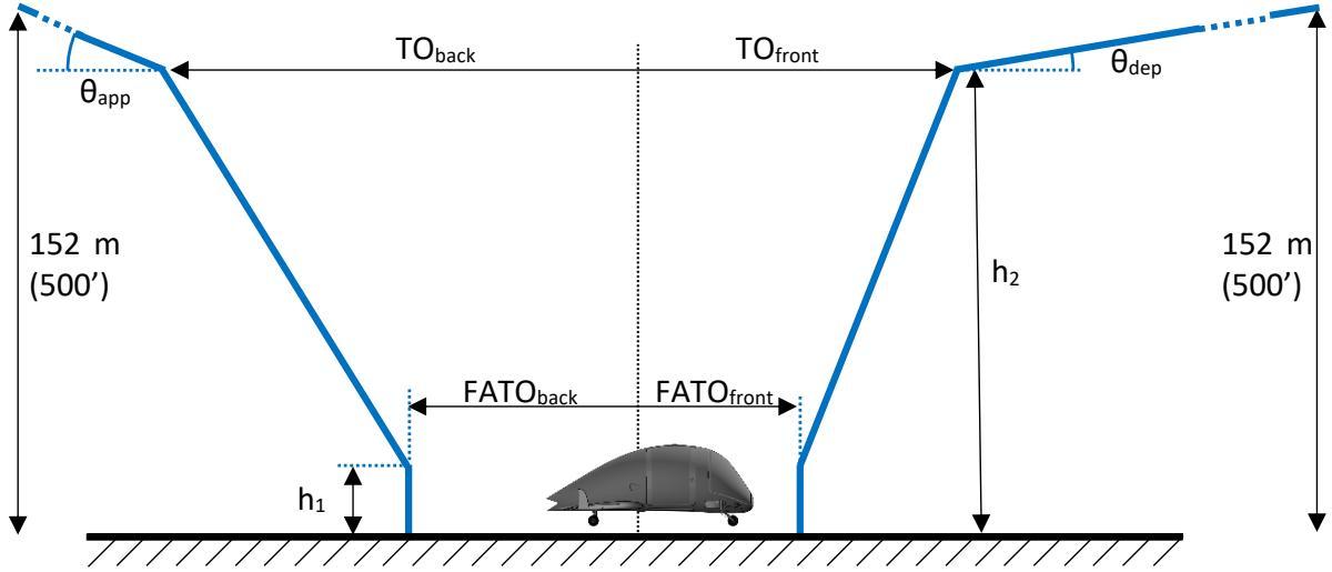
Figure D-13. Generic vertical take-off and landing procedure parameters

![42d547d506f004f02a14b1f4be44125d6c9917567cfe36be11450eaa13325317.jpg](https://aam-wiki.gksj.cc/uploads/images/gallery/2026-05/scaled-1680-/42d547d506f004f02a14b1f4be44125d6c9917567cfe36be11450eaa13325317.jpg)  
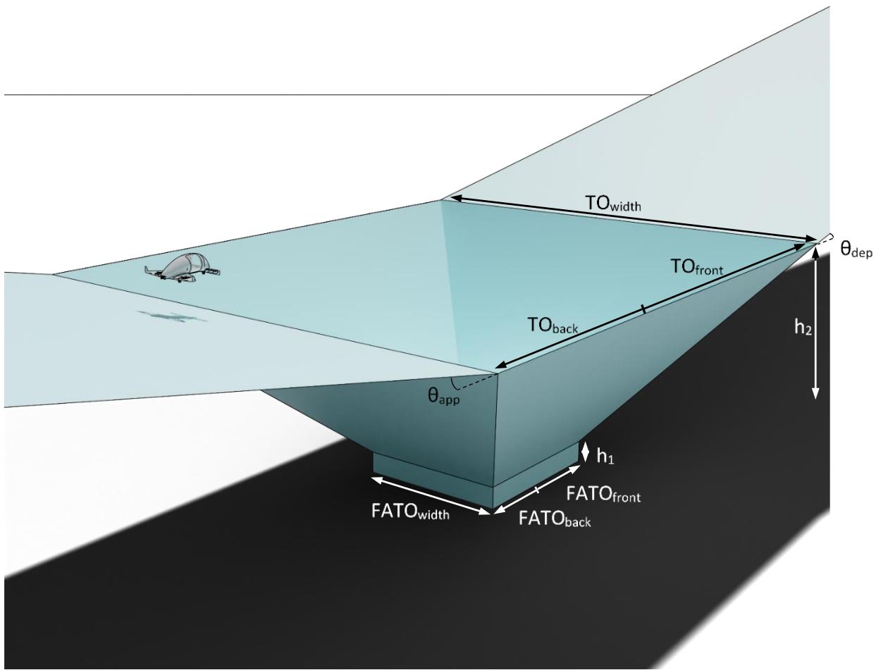
Figure D-14. Vertical take-off and landing procedure volume

(2) The FATO needed for the aircraft to perform an approved vertical take-off and landing procedure is characterised by the parameters $\mathsf { F A T O } _ { \mathsf { b a c k } _ { i } }$ , $\mathsf { F A T O } _ { \mathsf { f r o n t } }$ and $F A T O _ { w i d t h }$ . FATOback and $\mathsf { F A T O } _ { \mathsf { f r o n t } }$ are referenced to the centre of the smallest circle enclosing the aircraft, which is also used to define D (see MOC VTOL.2115). From the rectangular edges of the FATO, the procedure volume extends vertically to the low hover height $\mathsf { h } _ { 1 } ,$ from which it widens linearly up to the high hover height h2. At that height, the volume has the width ${ \mathsf { T O } } _ { \mathsf { w i d t h } }$ , while it extends to the back and to the front by the distances $\mathsf { T O } _ { \mathsf { b a c k } }$ and $\mathsf { T O } _ { \mathsf { f r o n t } }$ . At the back and the front edges, approach and departure surfaces are angled with gradients $\mathsf { \theta _ { a p p } }$ and $\theta _ { \mathsf { d e p } } .$ . Some aircraft can perform a turn during the climb, in which case the corresponding turn and climb capability will be provided in the AFM.

(3) To qualify as a vertical take-off and landing procedure, the parameters defining the procedure must meet certain minima or maxima as provided in Table D-3.

<table><tr><td rowspan=1 colspan=1>Parameter</td><td rowspan=1 colspan=1>Minimum/maximum</td></tr><tr><td rowspan=1 colspan=1> $\mathsf { h } _ { 1 }$ </td><td rowspan=1 colspan=1>-</td></tr><tr><td rowspan=1 colspan=1>h2</td><td rowspan=1 colspan=1>≥h1</td></tr><tr><td rowspan=1 colspan=1> $\mathsf { T O } _ { \mathsf { w i d t h } }$ </td><td rowspan=1 colspan=1>≤5D</td></tr><tr><td rowspan=1 colspan=1> $\mathsf { T O } _ { \mathsf { f r o n t } }$ </td><td rowspan=1 colspan=1>≤5D</td></tr><tr><td rowspan=1 colspan=1> $\mathsf { T O } _ { \mathsf { b a c k } }$ </td><td rowspan=1 colspan=1>≤5D</td></tr><tr><td rowspan=1 colspan=1> $\mathsf { F A T O } _ { \mathsf { w i d t h } }$ </td><td rowspan=1 colspan=1>≥ 1.5 D</td></tr><tr><td rowspan=1 colspan=1> $\mathsf { F A T O } _ { \mathsf { f r o n t } }$ </td><td rowspan=1 colspan=1>≥ 0.75 D</td></tr><tr><td rowspan=1 colspan=1> $\mathsf { F A T O } _ { \mathsf { b a c k } }$ </td><td rowspan=1 colspan=1>≥0.75 D</td></tr><tr><td rowspan=1 colspan=1> $\mathsf { \theta _ { a p p } }$ </td><td rowspan=1 colspan=1>≥4.5%</td></tr><tr><td rowspan=1 colspan=1> ${ \mathsf { \theta } } _ { \mathsf { d e p } }$ </td><td rowspan=1 colspan=1>≥4.5%</td></tr></table>

Table D-3. Vertical take-off and landing procedure parameters minima/maxima

(b) A vertiport obstacle-free volume compatible with the aircraft vertical take-off and landing procedure can be established as described in the following paragraphs.

## PTS VPT-DSN.D.450 Final-approach and take-off area (FATO) and safety area (SA)

(a) The minimum dimensions of the FATO should be:

(1) the length $\mathsf { F A T O } _ { \mathsf { b a c k } }$ behind the aircraft and the length $\mathsf { F A T O } _ { \mathsf { f r o n t } }$ in front of the aircraft, referenced to the VTOL-capable aircraft centre of the smallest enclosing circle; and

(2) the width $\mathsf { F A T O } _ { \mathsf { w i d t h } }$

(b) All other characteristics should be as per PTS1 VPT-DSN.C.210.

(c) The FATO should be surrounded by an SA as per PTS1 VPT-DSN.C.220.

Note: A larger SA may be warranted for specific local conditions, e.g. severe aerology.

## PTS VPT-DSN.D.455 Obstacle-free volume (OFV)

(a) The obstacle-free volume, as depicted in Figure D-15, is created by extending vertically upward the outside edges of the SA up to height h1. The edges at height h1 are then extended upwards linearly up to height $\mathsf { h } _ { 2 }$ to provide a funnel-shaped volume. At height $\mathsf { h } _ { 2 } ,$ 0.5 D are added on each side of the VTOL procedure volume so that the dimensions of the obstacle-free volume at height h2 are:

(1) the length $( \mathsf { T O } _ { \mathsf { b a c k } ^ { + } } 0 . 5 \mathsf { D } )$ behind the aircraft and the length $( \mathsf { T O } _ { \mathsf { f r o n t } } + \mathsf { O } . 5 ~ \mathsf { D } )$ in front of the VTOL-capable aircraft, referenced to the aircraft centre of the smallest enclosing circle when positioned on the FATO; and

(2) the width $( \mathsf { T O } _ { \mathsf { w i d t h } } + 1 \mathsf { D } )$

(b) The obstacle-free volume should not be penetrated by obstacles.

Note: A larger SA may be warranted for specific local conditions, e.g. severe aerology.

![d4bc0c34286474cc31457f681a5178cfcb00b9ab36a54fc32398ac84bc25e068.jpg](https://aam-wiki.gksj.cc/uploads/images/gallery/2026-05/scaled-1680-/d4bc0c34286474cc31457f681a5178cfcb00b9ab36a54fc32398ac84bc25e068.jpg)  
Figure D-15. SAs added to the vertical take-off and landing procedure parameters to establish the vertiport obstacle-free volume

## PTS VPT-DSN.D.460 Approach surface

(a) The limits of the OLS approach surface comprise:

(1) an inner edge, horizontal and equal in length to width $( \mathsf { T O } _ { \mathsf { w i d t h } } + 1 \mathsf { D } )$ located at the aft edge of the obstacle-free volume at height h2;

(2) two side edges originating at the ends of the inner edge diverging uniformly at a specified rate from the vertical plane containing the centre line of the FATO to a specified width and continuing thereafter at that width for the remaining length of the approach surface;

(3) an outer edge horizontal and perpendicular to the centre line of the approach surface at a height of 152 m (500 ft) above the elevation of the FATO, unless the en-route structure allows the OLS to stop at a lower altitude; and

(4) The slope of the approach surface is $\mathsf { \theta _ { a p p } }$ and should be measured in the vertical plane containing the centre line of the surface.

(b) All other characteristics should be as per PTS VPT-DSN.D.410.

## PTS VPT-DSN.D.465 Take-off climb surface

(a) The limits of the OLS take-off climb surface comprise:

(1) an inner edge, horizontal and equal in length to width $( \mathsf { T O } _ { \mathsf { w i d t h } } + 1 \mathsf { D } )$ located at the front edge of the obstacle-free volume at height h2;

(2) two side edges originating at the ends of the inner edge diverging uniformly at a specified rate from the vertical plane containing the centre line of the FATO to a specified width and continuing thereafter at that width for the remaining length of the take-off climb surface; and

(3) an outer edge horizontal and perpendicular to the centre line of the take-off climb surface at a height of 152 m (500 ft) above the elevation of the FATO, unless the en-route structure allows the OLS to stop at a lower altitude.

(4) The slope of the take-off climb surface is $\mathsf { \boldsymbol { \theta } } _ { \mathsf { d e p } }$ and should be measured in the vertical plane containing the centre line of the surface.

(b) All other characteristics should be as per PTS VPT-DSN.D.420.

(c) All other characteristics (e.g. transitional surface) as per PTS VPT-DSN, Chapter C – Physical characteristics and Chapter D, Subpart 1 – Obstacle limitation surfaces.

## PTS VPT-DSN.D.470 Bidirectional volume

A bidirectional volume (where each OLS can be used for both take-off climb and approach) can be created by taking the largest values of the front and back parameters of the vertical take-off and landing procedure and the lowest of the gradients (see Table D-4). To this volume the SAs should be added, and the obstacle-free volume derived as described in the preceding paragraphs.

<table><tr><td rowspan=1 colspan=1>Parameter</td><td rowspan=1 colspan=1>Bidirectional volume</td></tr><tr><td rowspan=1 colspan=1> $\mathsf { T O } _ { \mathsf { f r o n t b i d i r e c t i o n } } =$  $\mathsf { T O } _ { \mathsf { b a c k \thinspace b i d i r e c t i o n } }$ </td><td rowspan=1 colspan=1> $\mathsf { m a x } ( \mathsf { T O } _ { \mathsf { f r o n t } } , \mathsf { T O } _ { \mathsf { b a c k } } )$ </td></tr><tr><td rowspan=1 colspan=1> $\mathsf { F A T O } _ { \mathsf { f r o n t b i d i r e c t i o n } } =$  $\mathsf { F A T O _ { b a c k \ b i d i r e c t i o n } }$ </td><td rowspan=1 colspan=1> $\mathsf { m a x } ( \mathsf { F A T O } _ { \mathsf { f r o n t } } , \mathsf { F A T O } _ { \mathsf { b a c k } } )$ </td></tr><tr><td rowspan=1 colspan=1> $\mathsf { \theta _ { a p p b i d i r e c t i o n } = }$  $\mathsf { \theta _ { d e p \ b i d i r e c t i o n } }$ </td><td rowspan=1 colspan=1> $\mathsf { m i n } ( \mathsf { \theta } _ { \mathsf { a p p } } , \mathsf { \theta } _ { \mathsf { d e p } } )$ </td></tr></table>

Table D-4. Bidirectional VTOL procedure volume derived from vertical take-off and landing procedure parameters (without an SA)

## PTS VPT-DSN.D.475 Omnidirectional volume

(a) An omnidirectional VTOL procedure volume (where the final part of the approach or the initial part of the departure can be conducted from any direction) can be created by replacing the rectangular volumes with cylindrical volumes, and a conical OLS with the parameters given in Table D-5 (see also Figure D-16), centred on the centre of the smallest enclosing circle. From this procedure volume, the vertiport obstacle-free volume can be derived by adding 0.5 D or 6 m, whichever is greater, to the diameter at FATO level and 1 D at height h2 as an SA. The OLS starts at height $\mathsf { h } _ { 2 }$ on the circle with the added SA and finishes at a height of 152 m (500 ft) above the elevation of the FATO, unless the en-route structure allows the OLS to stop at a lower altitude.

<table><tr><td rowspan=1 colspan=1>Parameter</td><td rowspan=1 colspan=2>omnidirectional volume</td></tr><tr><td rowspan=1 colspan=1> $\emptyset \intercal 0 _ { \mathrm { o m n i d i r e c t i o n } }$ </td><td rowspan=1 colspan=2> $\mu \times \mathsf { m a x } ( \mathsf { T O } _ { \mathsf { f r o n t } } , \mathsf { T O } _ { \mathsf { b a c k } } ) ^ { 2 } + \mathsf { T O } _ { \mathsf { w i d t h } } ^ { 2 }$ √</td></tr><tr><td rowspan=1 colspan=1> $\emptyset \mathsf { F A T O } _ { \mathsf { o m n i d i r e c t i o n } }$ </td><td rowspan=1 colspan=1></td><td rowspan=1 colspan=1> $\sqrt { 4 \times \mathsf { m a x } ( \mathsf { F A T O } _ { \mathsf { f r o n t } } , \mathsf { F A T O } _ { \mathsf { b a c k } } ) ^ { 2 } + \mathsf { F A T O } _ { \mathsf { w i d t h } } ^ { 2 } }$ </td></tr><tr><td rowspan=1 colspan=1> $\mathsf { \theta _ { o m n i d i r e c t i o n } }$ </td><td rowspan=1 colspan=2>min $( \mathsf { \boldsymbol { \theta } } _ { \mathsf { a p p } } , \mathsf { \boldsymbol { \theta } } _ { \mathsf { d e p } } )$ </td></tr></table>

Table D-5. Omnidirectional VTOL procedure volume derived from vertical take-off and landing procedure parameters (without an SA)

![8b834ec3cd662776d27d3d6d512b8cab74ba3a6e88a0b32bfb253e04a52b232c.jpg](https://aam-wiki.gksj.cc/uploads/images/gallery/2026-05/scaled-1680-/8b834ec3cd662776d27d3d6d512b8cab74ba3a6e88a0b32bfb253e04a52b232c.jpg)  
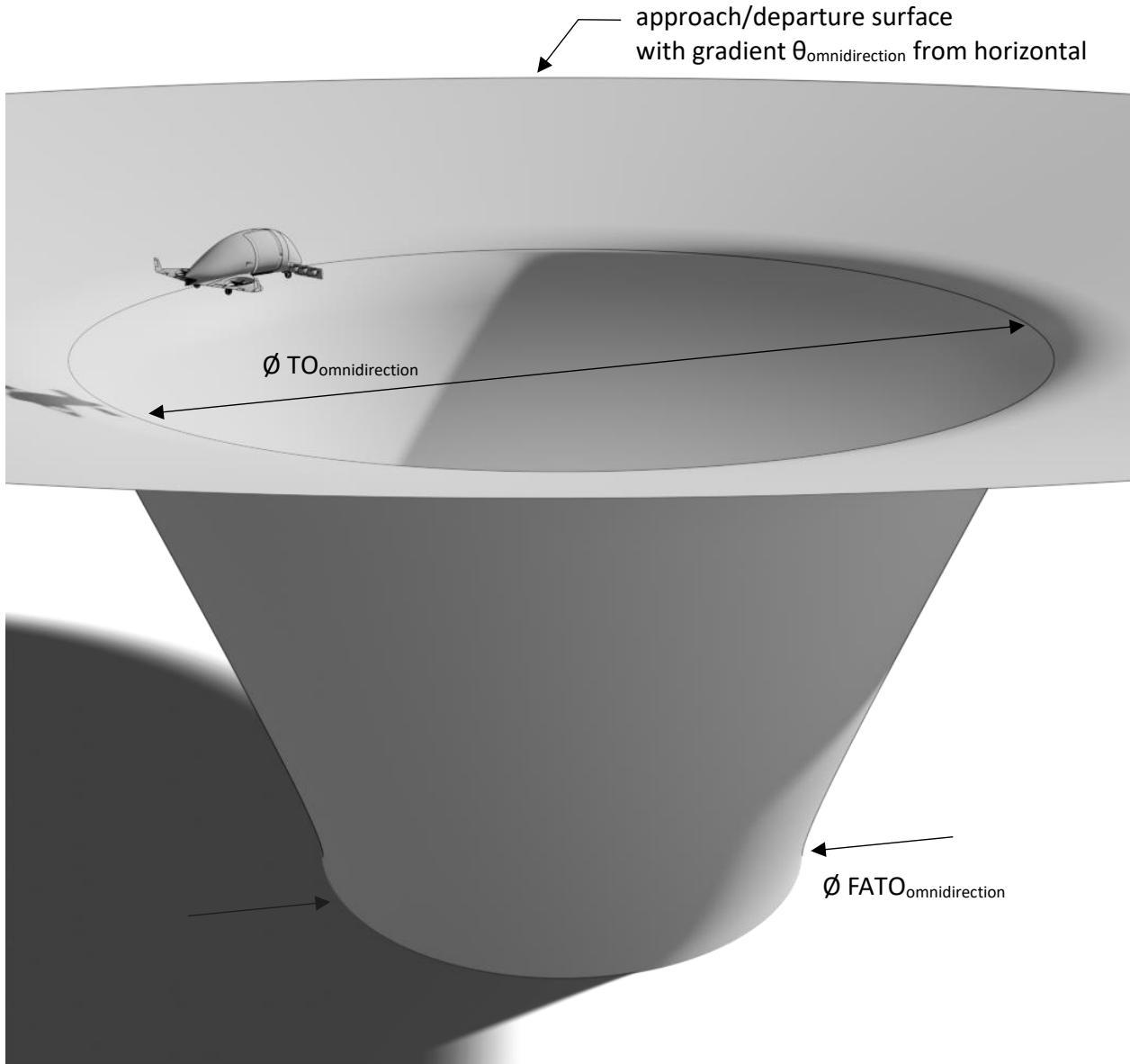
Figure D-16. VTOL procedure volume with omnidirectional approach and take-off climb surface (without SAs)

(b) If a VTOL-capable aircraft has been certified for a vertical procedure, it should be able to operate in the corresponding omnidirectional obstacle-free volume with conical OLS.

(c) Instead of a conical OLS, discrete planar approach and take-off climb surfaces (see Figure D-17 and Figure D-18), as per PTS VPT-DSN.D.410 and PTS VPT-DSN.D.420, can be created as follows:

(1) the inner edges are horizontal, equal in length to width $( \mathsf { T O } _ { \mathsf { o m n i d i r e c t i o n } } + 1 \mathsf { D } )$ , located at height h2 and tangent at their centre to the circle of diameter $( \mathsf { T O } _ { \mathsf { o m n i d i r e c t i o n } } + 1 \mathsf { D } )$ centred on the centre of the smallest enclosing circle;

(2) an additional horizontal surface bridges the space between the circle of diameter (TOomnidirection+1 D) and the inner edges of the OLS.

(d) It should be verified that a given VTOL-capable aircraft can operate in such a volume, e.g. can perform the turn between approach and take-off climb surfaces in case of a balked landing, without encroaching on the protection surfaces.

![ded3b424576b6350576fff5a3fba596fcf2a25acb69964e05455dd6a412271fa.jpg](https://aam-wiki.gksj.cc/uploads/images/gallery/2026-05/scaled-1680-/ded3b424576b6350576fff5a3fba596fcf2a25acb69964e05455dd6a412271fa.jpg)  
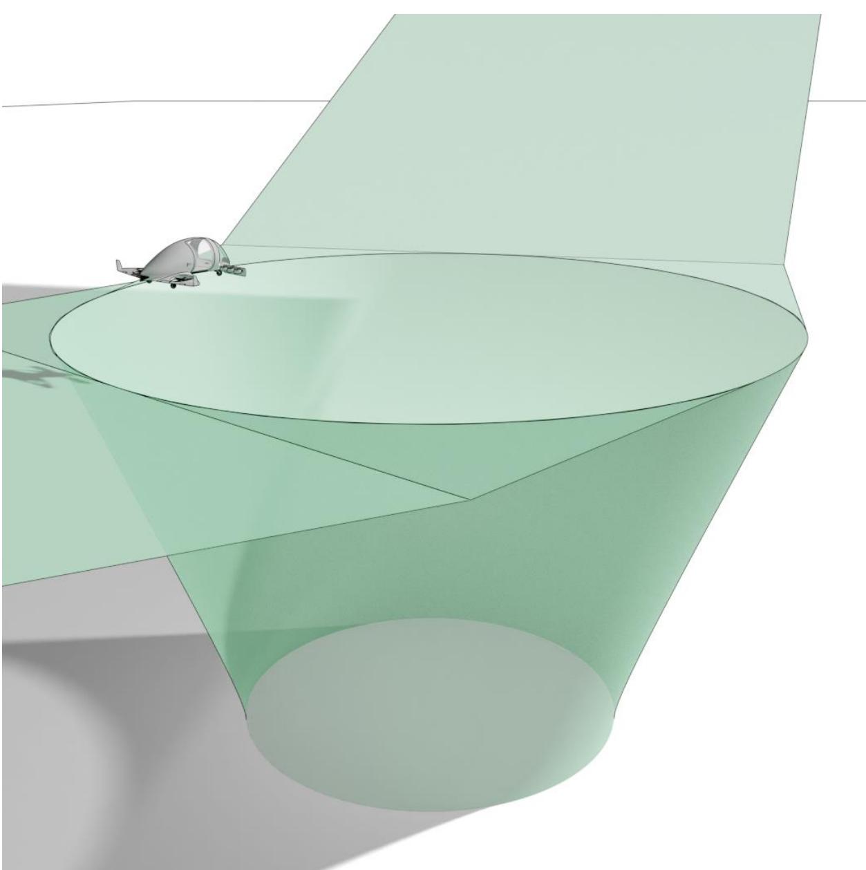
Figure D-17. Vertiport omnidirectional obstacle-free volume with discrete planar approach and take-off climb surfaces — perspective view

![787823b28addd65255ce18acb9aa85ebfb92c39888f5801940c323673b2da999.jpg](https://aam-wiki.gksj.cc/uploads/images/gallery/2026-05/scaled-1680-/787823b28addd65255ce18acb9aa85ebfb92c39888f5801940c323673b2da999.jpg)  
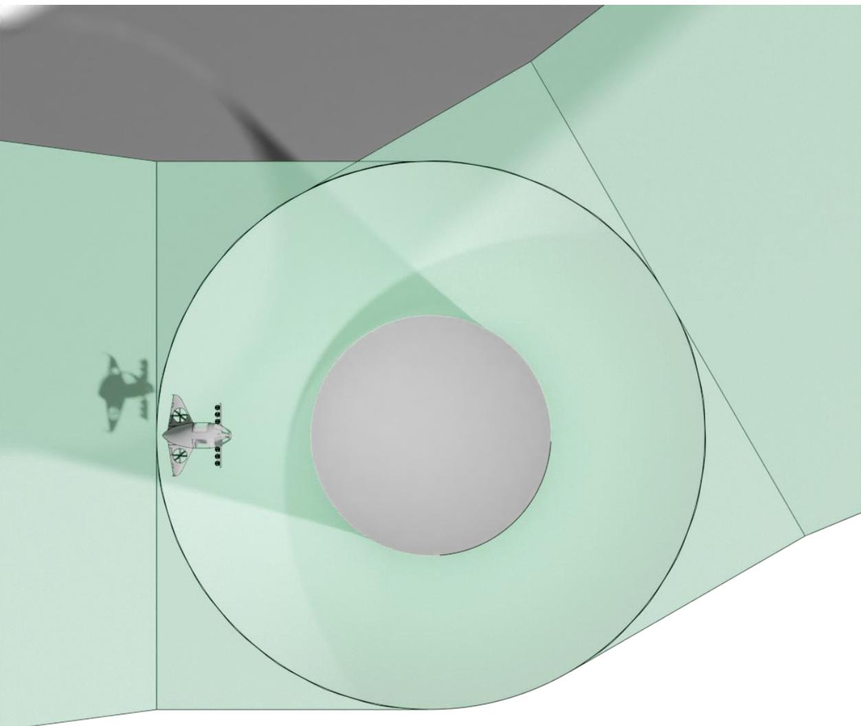
Figure D-18. Vertiport omnidirectional obstacle-free volume with discrete planar approach and take-off climb surfaces — top view

## PTS VPT-DSN.D.480 Omnidirectional obstacle-free volume with prohibited sector

(a) A sector of the omnidirectional obstacle-free volume with conical OLS can be declared prohibited, e.g. to avoid an obstacle (see Figure D-19 and Figure D-20).

(b) The prohibited sector is defined as follows:

(1) an inner edge coinciding at the FATO with the circle of diameter FATOomnidirection centred on the centre of the smallest enclosing circle. The inner surface extends vertically

upwards from this edge up to a height of 152 m (500 ft) above the elevation of the FATO, unless the en-route structure allows the OLS to stop at a lower altitude;

(2) two side planes originating at the ends of the inner edge diverging radially;

(3) an outer edge coinciding with the outer edge of the conical OLS. The outer surface extends vertically downwards down to the elevation of the FATO;

(4) an upper surface to close the sector, horizontal at height 152 m (500 ft), unless the enroute structure allows the OLS to stop at a lower altitude.

(c) It should be verified that a given VTOL-capable aircraft can operate in such a volume, e.g. can avoid the prohibited sector in case of a balked landing. Corresponding operational limitations should be set as necessary.

![8f70f31f3dde6e83889c1159223cb128e3247c3536174593175033e44ed59940.jpg](https://aam-wiki.gksj.cc/uploads/images/gallery/2026-05/scaled-1680-/8f70f31f3dde6e83889c1159223cb128e3247c3536174593175033e44ed59940.jpg)  
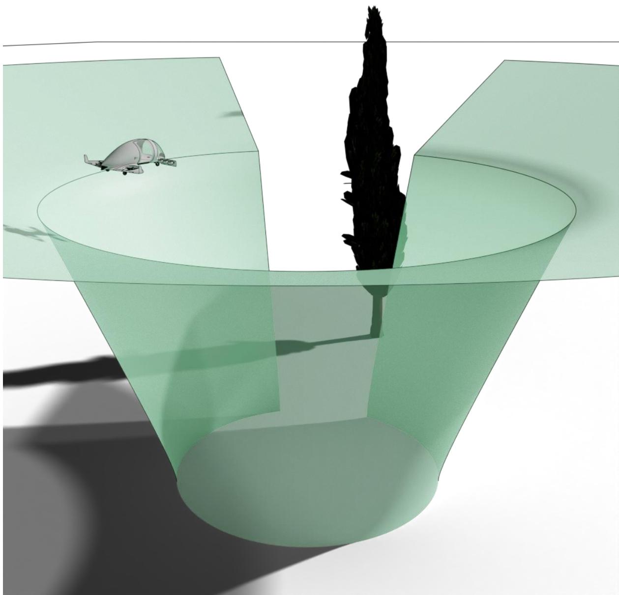
Figure D-19. Vertiport obstacle-free volume with omnidirectional approach and take-off climb surface and prohibited sector — perspective view

![93ff88aa1d3b62fecb331f05527f2116772b5076bc328da509c523d9ca8b38f1.jpg](https://aam-wiki.gksj.cc/uploads/images/gallery/2026-05/scaled-1680-/93ff88aa1d3b62fecb331f05527f2116772b5076bc328da509c523d9ca8b38f1.jpg)  
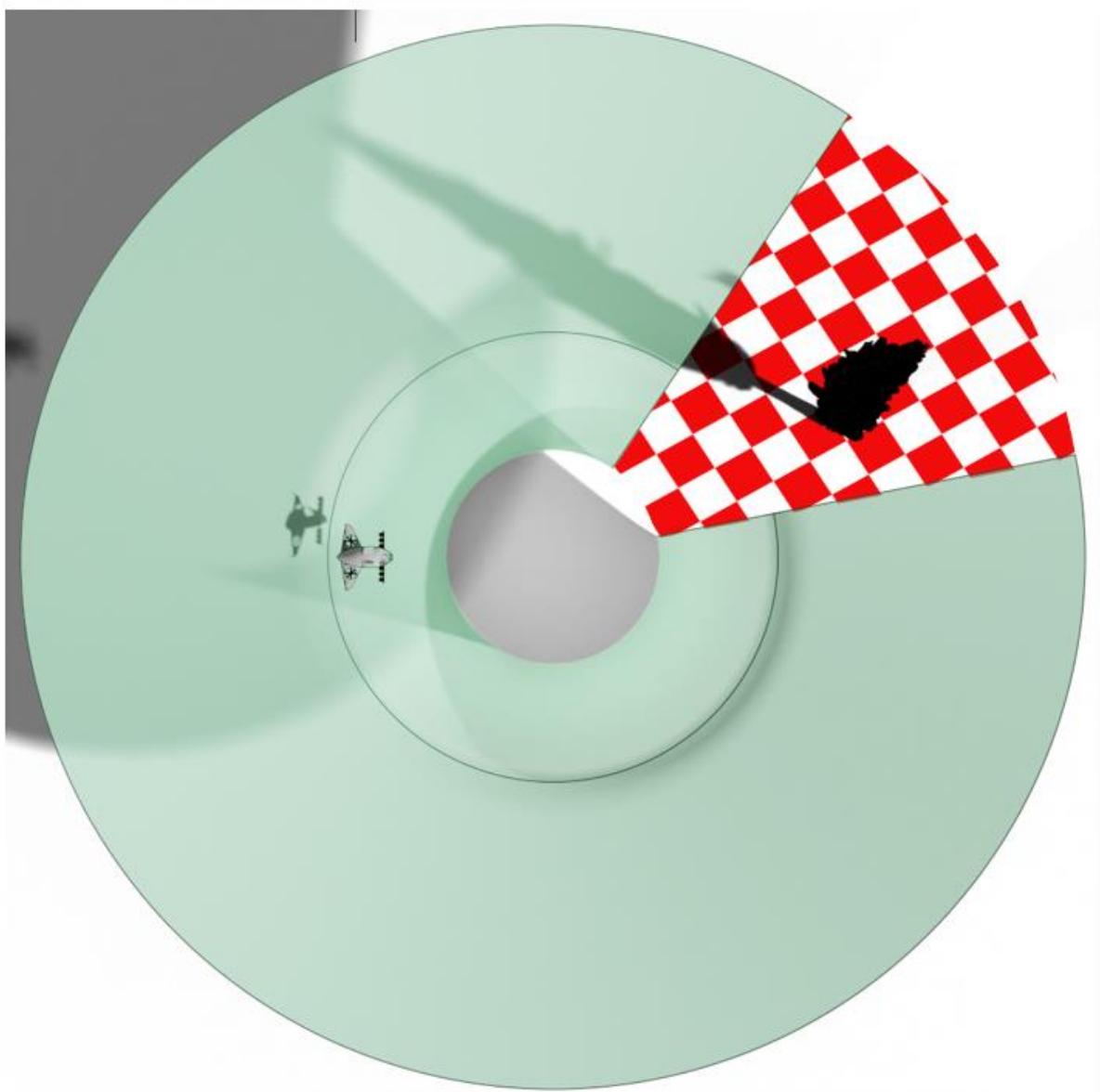
Figure D-20. Vertiport obstacle-free volume with omnidirectional approach and take-off climb surface and prohibited sector — top view

## PTS VPT-DSN.D.485 Reference volume Type 1

A specific vertical take-off and landing procedure has been foreseen with given values for the defining parameters to further facilitate standardisation of vertiports. The VTOL-capable aircraft manufacturer can voluntarily choose to demonstrate that the VTOL-capable aircraft can perform a vertical take-off and landing within this volume referred to as ‘Reference volume Type 1’. Additional reference volume types can be developed if deemed useful by the community.

(a) The Reference volume Type 1 dimensions with the SAs included are depicted on Table D-6 and Figure D-21:

<table><tr><td rowspan=1 colspan=1>Parameter</td><td rowspan=1 colspan=1>Reference volume Type 1</td></tr><tr><td rowspan=1 colspan=1> $\mathsf { h } _ { 1 }$ </td><td rowspan=1 colspan=1>3 m (10)</td></tr><tr><td rowspan=1 colspan=1> $\mathsf { h } _ { 2 }$ </td><td rowspan=1 colspan=1>30.5 m (100)</td></tr><tr><td rowspan=1 colspan=1> $\mathsf { T O } _ { \mathsf { w i d t h } }$ </td><td rowspan=1 colspan=1>3D</td></tr><tr><td rowspan=1 colspan=1> $\mathsf { T O } _ { \mathsf { f r o n t } }$ </td><td rowspan=1 colspan=1>2D</td></tr><tr><td rowspan=1 colspan=1> $\mathsf { T O } _ { \mathsf { b a c k } }$ </td><td rowspan=1 colspan=1>2D</td></tr><tr><td rowspan=1 colspan=1> $\mathsf { F A T O } _ { \mathsf { w i d t h } }$ </td><td rowspan=1 colspan=1>2D</td></tr><tr><td rowspan=1 colspan=1> $\mathsf { F A T O } _ { \mathsf { f r o n t } }$ </td><td rowspan=1 colspan=1>1D</td></tr><tr><td rowspan=1 colspan=1> $\mathsf { F A T O } _ { \mathsf { b a c k } }$ </td><td rowspan=1 colspan=1>1D</td></tr><tr><td rowspan=1 colspan=1> ${ \underline { { \theta _ { \mathsf { a p p } } } } }$ </td><td rowspan=1 colspan=1>12.5 %</td></tr><tr><td rowspan=1 colspan=1> $\theta _ { \mathsf { d e p } }$ </td><td rowspan=1 colspan=1>12.5 %</td></tr></table>

Table D-6. Reference volume Type 1 parameters (with the SAs)

![55422f639097d36cfa7590e57349419d07ad7b33bd893eef8d2bc4155c498cac.jpg](https://aam-wiki.gksj.cc/uploads/images/gallery/2026-05/scaled-1680-/55422f639097d36cfa7590e57349419d07ad7b33bd893eef8d2bc4155c498cac.jpg)  
Figure D-21. Reference volume Type 1 dimensions (with the SAs)

(b) A Reference volume Type 1 is by design bidirectional.

(c) An omnidirectional vertiport obstacle-free volume can be derived from the Reference volume Type 1 and has then the dimensions given in Table D-7.

<table><tr><td rowspan=1 colspan=1>Parameter</td><td rowspan=1 colspan=1>omnidirectional volume</td></tr><tr><td rowspan=1 colspan=1> $\mathsf { h } _ { 1 }$ </td><td rowspan=1 colspan=1>3m (10)</td></tr><tr><td rowspan=1 colspan=1> $\mathsf { h } _ { 2 }$ </td><td rowspan=1 colspan=1>30.5 m (100)</td></tr><tr><td rowspan=1 colspan=1> $\emptyset \intercal 0 _ { \mathrm { o m n i d i r e c t i o n } }$ </td><td rowspan=1 colspan=1>5D</td></tr><tr><td rowspan=1 colspan=1> $\emptyset \mathsf { F A T O } _ { \mathsf { o m n i d i r e c t i o n } }$ </td><td rowspan=1 colspan=1>2.83 D</td></tr><tr><td rowspan=1 colspan=1> $\mathsf { \theta _ { o m n i d i r e c t i o n } }$ </td><td rowspan=1 colspan=1>12.5%</td></tr></table>

Table D-7. Omnidirectional vertiport obstacle-free volume derived from the Reference volume Type 1 (with the SAs)

Examples of the potential vertiports with the Reference volume Type 1 established in congested urban areas (for illustration purposes only; the actual suitability has not been assessed) are presented in Figure D-22.

![9632586e61f3021f78d31f947f04713aa09a979d25fc2e65001767ef8b465985.jpg](https://aam-wiki.gksj.cc/uploads/images/gallery/2026-05/scaled-1680-/9632586e61f3021f78d31f947f04713aa09a979d25fc2e65001767ef8b465985.jpg)

![33b2c020254bd7ed81daae910ae2377a97461e562111ac596ab09f70ad7ad6fa.jpg](https://aam-wiki.gksj.cc/uploads/images/gallery/2026-05/scaled-1680-/33b2c020254bd7ed81daae910ae2377a97461e562111ac596ab09f70ad7ad6fa.jpg)

![c57ed895d575e4626ec62f8096dc459ccf53aec43d58f9a28baa96016b8ffe65.jpg](https://aam-wiki.gksj.cc/uploads/images/gallery/2026-05/scaled-1680-/c57ed895d575e4626ec62f8096dc459ccf53aec43d58f9a28baa96016b8ffe65.jpg)

![0e8e85963e6010db98999ce77c8e238f6c08c2a064c80c7ac463d99dccc3e82c.jpg](https://aam-wiki.gksj.cc/uploads/images/gallery/2026-05/scaled-1680-/0e8e85963e6010db98999ce77c8e238f6c08c2a064c80c7ac463d99dccc3e82c.jpg)  
Figure D-22. Examples of potential vertiports with Reference volume Type 1 (for illustration purposes only; the actual suitability has not been assessed)

## PTS VPT-DSN.D.490 Link to VTOL-capable aircraft requirements

Requirements have been established for the aircraft designer to facilitate vertiport design; for example, to report certain characteristics of the aircraft in the AFM. Below are some of these requirements contained in EASA Special Condition VTOL and its corresponding Means of Compliance. Some requirements are still under development and the different documents can be found at https://www.easa.europa.eu/domains/rotorcraft-vtol/VTOL.

## Dimension ‘D’

‘D’ means the diameter of the smallest circle enclosing the VTOL aircraft projection on a horizontal plane, while the aircraft is in the take-off or landing configuration, with rotor(s) turning, if applicable (Figure D-23). Publish D in metres, rounded up to the next tenth. If the VTOL aircraft changes dimension during taxi or parking (e.g. folding wings), a corresponding Dtaxi and Dparking should also be provided.

![0cefbb439c2d24a38fa509986660a90caf37fedca60581afd786c4e9689e8659.jpg](https://aam-wiki.gksj.cc/uploads/images/gallery/2026-05/scaled-1680-/0cefbb439c2d24a38fa509986660a90caf37fedca60581afd786c4e9689e8659.jpg)  
Figure D-23. Dimension ‘D’ and centre of the smallest enclosing circle

An example of difference between the largest overall dimension and the diameter of the smallest enclosing circle is provided in Figure D-24. Appendix 1 provides clarification that if the largest overall dimension for obstacle protection is used, there could be a 15 % error in the unsafe direction. For VTOL-capable aircraft, the dimension D used for obstacle protection and vertiport design is thus defined based on the smallest enclosing circle, as stated above.

![84c31a9418b3f3b21464062efbda102a7f3872dff9a012d46259dbcc8adb19c7.jpg](https://aam-wiki.gksj.cc/uploads/images/gallery/2026-05/scaled-1680-/84c31a9418b3f3b21464062efbda102a7f3872dff9a012d46259dbcc8adb19c7.jpg)  
Figure D-24. Example of unsafe difference between the largest overall dimension and the diameter of the smallest enclosing circle

‘Undercarriage width’ (UCW) means the maximum width of the undercarriage/landing gear projection on a horizontal plane (Figure D-25). The UCW should be published in metres, rounded up to the next tenth.

![ac81db0edc347082f8000737ec7b2a8d08365f2d0879470c8f7814a1d1d90303.jpg](https://aam-wiki.gksj.cc/uploads/images/gallery/2026-05/scaled-1680-/ac81db0edc347082f8000737ec7b2a8d08365f2d0879470c8f7814a1d1d90303.jpg)  
Figure D-25. Undercarriage width

## Undercarriage footprint

‘Undercarriage’ footprint means the diameter of the circle containing the landing gear contact area while the aircraft is in the take-off or landing configuration (Figure D-26). The undercarriage footprint can be used for the determination of the undercarriage containment area and the TLOF. The undercarriage footprint should be published in metres, rounded up to the next tenth.

![33901b2d3d867e127f660c061071e8c2312f62c22554d88c4715bb965b476987.jpg](https://aam-wiki.gksj.cc/uploads/images/gallery/2026-05/scaled-1680-/33901b2d3d867e127f660c061071e8c2312f62c22554d88c4715bb965b476987.jpg)  
Figure D-26. Undercarriage footprint

Take-off performance  
![37935726dce5f0bdde5b789a62dde15254ae796f336f9bbc7c097e7b4d19a1b7.jpg](https://aam-wiki.gksj.cc/uploads/images/gallery/2026-05/scaled-1680-/37935726dce5f0bdde5b789a62dde15254ae796f336f9bbc7c097e7b4d19a1b7.jpg)  
Figure D-27. Possible take-off paths

Note A: The altitudes of 200 ft and 1 000 ft are proposed in the development of the take-off flight path as currently used for Category A helicopters. Different take-off heights can be considered if compatible with the departure and en-route structure; in particular, accelerating from VTOSS to VFTO at a higher altitude allows to leave the obstacle environment faster.

Landing performance

![96229ddf263cb9575c31b077ef380c0b0fc15f781c7bc2d3c9cf9e4f2193027d.jpg](https://aam-wiki.gksj.cc/uploads/images/gallery/2026-05/scaled-1680-/96229ddf263cb9575c31b077ef380c0b0fc15f781c7bc2d3c9cf9e4f2193027d.jpg)  
Figure D-28. Landing path

# CHAPTER E — VISUAL AIDS

<table><tr><td colspan="2">Rationale</td></tr><tr><td>1. 2.</td><td>The specifications for wind direction indicator, marking and markers have been adapted from Annex 14, Volume II, Heliports, 5th edition, Amendment 9. All notes from Annex 14 referring to guidance in ICAO Document 9261, Heliport Manual, have been included in the specifications. All PTS specifications are considered as guidance material, so the term &#x27;should&#x27; is used instead</td></tr><tr><td>3.</td><td>of &#x27;shall&#x27; for Annex 14 Standards. The term &#x27;may&#x27; is kept when the text is derived from material adapted from the Heliport Manual. The specifications must be reviewed after data of the VTOL-capable aircraft from the</td></tr><tr><td>4.</td><td>manufactures are received. AIll specifications are preceded by the objective of the visual aid, taken from ICAO Annex 14</td></tr><tr><td>5.</td><td>or the Heliport Manual. Offshore installations from Annex 14 are not included in this PTS, as VTOL offshore and sling/hoist operations are not expected in the near future. The following sections from ICAO</td></tr><tr><td></td><td>Annex 14, Volume Il, Heliports have been deleted and all subsequent sections renumbered: Winching area marking Helideck obstacle-free sector (chevron) marking</td></tr><tr><td>6.</td><td>Helideck and shipboard heliport surface marking Runway-type FATOs can be useful for VTOL-capable aircraft with the ability to use such runways.</td></tr><tr><td>7.</td><td>New sections have been included: PTS VPT-DSN.E.530 FATO identification marking. To provide a marking to differentiate</td></tr><tr><td></td><td>FATOs in close proximity. pTs VPT-DSN.E.670 Apron safety lines. To provide markings for the limits for ground equipment. The battery replacement equipment can be large. The text is in line with</td></tr><tr><td></td><td>CS ADR-DSN.L.595 Apron safety lines and the associated GM. PTs VPT-DsN.E.680 Visual aids for denoting restricted use areas. To provide marking</td></tr><tr><td>8.</td><td>for closed FATOs, TLOFs, stands and taxiways and to mark areas under maintenance. This text is in line with CS ADR-DSN.R.855, CS ADR-DSN.R.870 and the associated GM. The dimensions of all markings will have to be reviewed when input from the manufacturers</td></tr><tr><td>9.</td><td>on the size of the FATOs for VTOL-capable aircraft is received. The colour scheme of Annex 14 and CS-HPT-DSN for markings and markers is proposed to be kept for conspicuity, and it is proposed to provide the differentiation for heliports and vertiports with the vertiport identification marking.</td></tr></table>

## PTS VPT-DSN.E.500 Visual aids – General

Note 1: The PTS on the runway-type FATO is provided in this PTS edition pending decision on its applicability to VTOL-capable aircraft.

(a) The procedures used by some VTOL-capable aircraft require that they utilise a FATO having characteristics similar in shape to a runway for fixed wing aircraft. An FATO having characteristics similar in shape to a runway is considered to be satisfying the concept for a ‘runway-type FATO’. For such arrangements, it is sometimes necessary to provide specific markings to enable a pilot to distinguish a runway-type FATO during an approach. Appropriate markings are contained within paragraph entitled ‘Runway-type FATOs’. The requirements applicable to all other types of FATOs are given within paragraphs entitled ‘All FATOs except runway-type FATOs’.

(b) Unless otherwise specified, the specifications for a colour referred to within PTS-VPT-DSN should be those contained in CS-ADR-DSN.

(c) The FATO may contain additional markings that support vertical approach or take-off subject to the specifications of Chapter D, Subpart 2, provided they do not interfere with other markings within or near the FATO and their meanings.

Note 2: It has been found that, on vertiport surfaces of light colour, the conspicuity of white markings can be improved by outlining them in black.

## PTS VPT-DSN.E.510 Wind direction indicator

## Rationale

1. New text on the objective of the wind direction indicator has been included from the Heliport Manual.

2. The term ‘rotor downwash’ has been adapted to read ‘downwash from the lift/thrust units’; the term that has been taken from EASA SC-VTOL-1.

3. A new location for wind direction indicator for vertiport that is elevated or an obstacle-free volume FATO has been included.

4. Guidance on the wind sleeve location has been taken from the Heliport Manual.

5. The possibility to obtain meteorological information from meteorological stations has been included. Meteorological information could be certified and transmitted within the appropriate service such ATIS, UNICOM of AFIS, all to be aligned with ATM developments.

6. The sizes of wind direction indicator are kept. The sizes depend on the ability of the pilot to see the wind direction indicator.

(a) The objective of the wind direction indicator is to provide the pilot with a visual indication of the wind direction and give an indication of the wind speed in the vicinity of the FATO and TLOF.

## (b) Applicability

A vertiport should be equipped with at least one wind direction indicator.

## (c) Location

(1) A wind direction indicator should be located so as to indicate the wind conditions over the FATO and TLOF and in such a way as to be free from the effects of airflow disturbances caused by nearby objects or downwash from the lift/thrust units. It should be visible from a VTOL aircraft in flight, in a hover or on the movement area.

(2) At vertiports that are elevated or where an obstacle-free volume is provided, the wind direction indicator may be located at a nearby structure.

(3) Where a TLOF and/or FATO may be subject to a disturbed airflow, additional wind direction indicators located close to the area should be provided to indicate the surface wind on the area.

(4) The indicator should be sited to avoid the effects of turbulence and should be of sufficient size to be visible from VTOL aircraft flying at a height of 200 m. Where a TLOF may be subjected to a disturbed air flow, then additional small lightweight wind vanes located close to the area may prove useful.

(5) For FATOs located in environments where the airflow may be disturbed by nearby objects, such as in urban vertiports and congested areas, where more than one wind direction indicator may be needed, or when the wind direction indicators may be difficult to place near the FATO that is elevated, information on the wind direction and speed and other wind characteristics such as gusts or turbulence may be obtained from meteorological stations located near the FATO and be broadcasted/radio transmitted to the pilots.

## (d) Characteristics

(1) A wind direction indicator should be constructed so that it gives a clear indication of the direction of the wind and a general indication of the wind speed.

(2) A wind direction indicator should be a truncated cone made of lightweight fabric and should have the following minimum dimensions:

<table><tr><td colspan="2">Surface level VPT</td><td>VPT that is elevated</td></tr><tr><td>Length</td><td>2.4m</td><td>1.2m</td></tr><tr><td>Diameter (larger end)</td><td>0.6 m</td><td>0.3 m</td></tr><tr><td>Diameter (smaller end)</td><td>0.3m</td><td>0.15 m</td></tr></table>

(3) The colour of the wind direction indicator should be so selected as to make it clearly visible and understandable from a height of at least 200 m (650 ft) above the vertiport, having regard to background. Where practicable, a single colour, preferably white or orange, should be used. Where a combination of two colours is required to give adequate conspicuity against changing backgrounds, they should preferably be orange and white, red and white, or black and white, and should be arranged in five alternate bands the first and last band being the darker colour.

(4) A wind direction indicator at a vertiport intended for use at night should be illuminated.

## PTS VPT-DSN.E.520 Vertiport identification marking

## Rationale

<table><tr><td>1. A vertiport identification marking consisting of a &#x27;V&#x27; letter inside a blue circle has been proposed and agreed. See figures. However, the input from pilot view after simulating approach and landing at vertiports wil be used for the final decision. Commentators are invited to provide their feedback. 2. The dimensions of all markings wil have to be reviewed when input from the manufacturers</td></tr></table>

(a) The objective of a vertiport identification marking is to provide the pilot with an indication of the presence of a vertiport; with its form, likely usage; and, the preferred direction(s) of approach.

## (b) Applicability

A vertiport identification marking should be provided at a vertiport.

## (c) Location — all FATOs except runway-type FATOs

(1) A vertiport identification marking should be located at or near the centre of the FATO.

(2) Where a vertiport that is elevated or an obstacle-free volume is provided, the vertiport identification marking should be located within the FATO or TLOF.

(3) If the TDPM is offset, the vertiport identification marking should be established in the centre of the TDPM.

(4) On a FATO which does not contain a TLOF, and which is marked with an aiming point marking (see PTS VPT-DSN.E.580), the vertiport identification marking should be established in the centre of the aiming point marking as shown in Figure E-1 and Figure E-2.

(5) On a FATO which contains a TLOF, a vertiport identification marking should be located within the FATO so the position of it coincides with the centre of the TLOF.

## (d) Location — runway-type FATOs

A vertiport identification marking should be located within the FATO and when used in conjunction with FATO designation markings, should be displayed at each end of the FATO as shown in Figure E-3.

## (e) Characteristics

(1) A vertiport identification marking, except for a vertiport at a hospital, should consist of a letter ‘V’ in white inside a blue circle. The dimensions of the ‘V’ and the blue circle markings should be no less than those shown in Figure E-4.

Note: The colour conspicuity of the blue circle and the dimensions should be tested and confirmed in simulators.

(2) A vertiport identification marking for a vertiport at a hospital should consist of a letter ‘V’ in red inside a blue circle, on a white cross made of squares adjacent to each of the sides of a square containing the ‘V’ as shown in Figures E-2 and E-4.

(3) A vertiport identification marking should be oriented with its symmetry axis aligned with the preferred final approach direction and so arranged as to be readable from the preferred final approach direction.

![54c50e031c92ace52f3402d6be6e029cb331ff6af7379674788f7bb5244314c3.jpg](https://aam-wiki.gksj.cc/uploads/images/gallery/2026-05/scaled-1680-/54c50e031c92ace52f3402d6be6e029cb331ff6af7379674788f7bb5244314c3.jpg)  
Note. - The aiming point, vertiport identification and FATO perimeter marking are white and may be edged with a 10 cm black border to improve contrast

Figure E-1. Combined vertiport identification, aiming point and FATO perimeter marking

![a84a7730422a68595a327574de43b5f148cf6f46be16892d1eecb8476caee868.jpg](https://aam-wiki.gksj.cc/uploads/images/gallery/2026-05/scaled-1680-/a84a7730422a68595a327574de43b5f148cf6f46be16892d1eecb8476caee868.jpg)  
Figure E-2. Vertiport identification markings with TLOF and aiming markings for vertiport and hospital vertiport

![a78f09f013c16fbe41dcc6b649b4fd2abeedd442313800aa4946a6651189dffe.jpg](https://aam-wiki.gksj.cc/uploads/images/gallery/2026-05/scaled-1680-/a78f09f013c16fbe41dcc6b649b4fd2abeedd442313800aa4946a6651189dffe.jpg)  
Figure E-3. FATO designation marking and vertiport identification marking for a runway-type FATO

![692732b5978fdfee6e667942000e5a6da437d50979ae638abf66577ce3768949.jpg](https://aam-wiki.gksj.cc/uploads/images/gallery/2026-05/scaled-1680-/692732b5978fdfee6e667942000e5a6da437d50979ae638abf66577ce3768949.jpg)  
Figure E-4. Hospital vertiport identification and vertiport identification marking

## PTS VPT-DSN.E.530 FATO identification marking

<table><tr><td>Rationale</td><td></td></tr><tr><td></td><td>A FATO identification marking to distinguish between close FATOs has been proposed. See figures.</td></tr><tr><td></td><td>(a)  The objective of the FATO identification markings is to provide the pilot with an identification of different FATOs at vertiport equipped with two or more FATOs.</td></tr><tr><td>(b)</td><td>FATO identification markings are not intended to be used in runway-type FATOs where the differentiation can be provided by the designation markings.</td></tr><tr><td>(c)</td><td>Applicability Where appropriate for differentiation, FATO identification markings should be provided.</td></tr><tr><td>(d) Location</td><td></td></tr><tr><td></td><td>A FATO identification marking should be located within the FATO and so arranged as to be readable from the preferred final approach direction.</td></tr><tr><td></td><td>
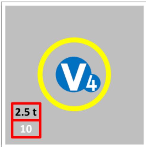
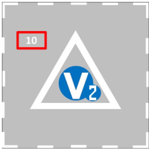
(e) Characteristics (1) Each FATO identification marking should consist of an ordinal number, beginning with 1</td></tr><tr><td></td><td>and ending in the last of the numbered FATOs (see Figure E-5).</td></tr><tr><td></td><td></td></tr><tr><td></td><td></td></tr><tr><td></td><td></td></tr><tr><td></td><td></td></tr><tr><td></td><td></td></tr><tr><td></td><td></td></tr><tr><td></td><td></td></tr><tr><td></td><td>(2) The numbers wil have the size and proportions shown in Figure E-6.</td></tr><tr><td></td><td></td></tr><tr><td></td><td></td></tr><tr><td></td><td></td></tr><tr><td></td><td></td></tr><tr><td></td><td></td></tr><tr><td></td><td></td></tr><tr><td></td><td></td></tr><tr><td></td><td></td></tr><tr><td></td><td></td></tr><tr><td></td><td></td></tr><tr><td></td><td></td></tr><tr><td></td><td></td></tr><tr><td></td><td></td></tr><tr><td></td><td></td></tr><tr><td></td><td></td></tr><tr><td></td><td></td></tr><tr><td></td><td></td></tr><tr><td></td><td></td></tr><tr><td></td><td></td></tr><tr><td></td><td></td></tr><tr><td></td><td></td></tr><tr><td></td><td></td></tr><tr><td></td><td></td></tr><tr><td></td><td></td></tr><tr><td></td><td></td></tr><tr><td></td><td></td></tr><tr><td></td><td></td></tr><tr><td></td><td></td></tr><tr><td></td><td></td></tr><tr><td></td><td></td></tr><tr><td></td><td></td></tr></table>

(3) The FATO identification number will be inside a blue circle with diameter 175 cm as shown in Figure E-5.

![8be6c0dd7be566a1063a886caf1e028fb3172b7adb9cc60666ca337a59f0b055.jpg](https://aam-wiki.gksj.cc/uploads/images/gallery/2026-05/scaled-1680-/8be6c0dd7be566a1063a886caf1e028fb3172b7adb9cc60666ca337a59f0b055.jpg)  
V height 260 cm Vwidth 260 cm V base 70 cm V line width 60 cm V vertex height 90 cm Blue circle  340 cm  
FATO/TLOF 15x15 m TLOF perimeter line width 30 cm TDPM inner circle  6,2 m TDPM line width 0,5 m

![ff057fc614db3494a4e840b9ecbed8cf1854374ca2a451204960fdad9b81d0b4.jpg](https://aam-wiki.gksj.cc/uploads/images/gallery/2026-05/scaled-1680-/ff057fc614db3494a4e840b9ecbed8cf1854374ca2a451204960fdad9b81d0b4.jpg)

V height 260 cm V width 260 cm V base 70 cm V line width 60 cm V vertex height 90 cm Blue circle  340 cm

FATO 15x15 m FATO dashed line 150x30 cm

Aiming point marking 9 m side triangle Number height 150 cm Number width 30-100 cm Separation V – Number 30 cm Small blue circle  175 cm

![e2dc49ef27d312159301d7a16fa015c97da384bdde8fc8ddd04d77a4e648c305.jpg](https://aam-wiki.gksj.cc/uploads/images/gallery/2026-05/scaled-1680-/e2dc49ef27d312159301d7a16fa015c97da384bdde8fc8ddd04d77a4e648c305.jpg)

V height 260 cm   
V width 260 cm   
Blue circle  340 cm   
Number height 150 cm   
Number width 30-100 cm   
Separation V – Number 30 cm   
Small blue circle  175 cm

FATO/TLOF 15x15 m TLOF perimeter line width 30 cm

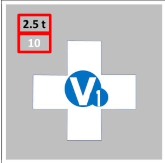
Hospital cross height 9 m Hospital cross width 9 m

Figure E-5. Vertiport identification, FATO identification, maximum allowable mass and D-value markings

## PTS VPT-DSN.E.540 Maximum allowable mass marking

## Rationale

1. Only metric units are employed for maximum allowable mass marking and D-value marking. Imperial units are not used in the EU.

2. The reference to shipboard vertiports (offshore) has been eliminated.

3. The mass is applicable only when required, to avoid proliferation of markings in the FATO; the distinctions between elevated and surface level vertiports have been eliminated to avoid duplication.

4. According to the actual masses of the VTOL in development (Volocity 900 kg (D 11,3 m) Lilium Jet 640 kg (D 13,9 m) CityAirbus 2 200 kg (D 8 m)), it has been proposed to use a two- or three-digit number (mass expressed to the nearest 100 kg) and eliminate the one-digit number (1 000 kg) for greater precision.

(a) The objective of the maximum allowable mass marking is to provide the mass limitation of the vertiport such that it is visible to the pilot from the preferred final approach direction.

## (b) Applicability

When required, a maximum allowable mass marking should be displayed at a vertiport.

## (c) Location

A maximum allowable mass marking should be located within the TLOF or FATO and so arranged as to be readable from the preferred final approach direction.

## (d) Characteristics

(1) A maximum allowable mass marking should consist of a two- or three-digit number.

(2) The maximum allowable mass should be expressed to the nearest 100 kg. The marking should be presented to one decimal place and rounded to the nearest 100 kg followed by the letter ‘t’. The decimal place should be preceded with a decimal point marked with a 30-cm square.

## (3) All FATOs except runway-type FATOs

The numbers and the letter of the marking should have a colour contrasting with the background and should be in the form and proportion shown in Figure E-6 for a D-value of more than 30 m. For a D-value between 15 m and 30 m, the height of the numbers and the letter of the marking should be a minimum of 90 cm, and for a D-value of less than 15 m, the height of the numbers and the letter of the marking should be a minimum of 60 cm, each with a proportional reduction in width and thickness.

## (4) Runway-type FATOs

The numbers and the letter of the marking should have a colour contrasting with the background and should be in the form and proportion shown in Figure E-6.

![2cdd86ddcf777766223a626ed8a51a549b49fcbbe1d5001457c4d90a37bb2be9.jpg](https://aam-wiki.gksj.cc/uploads/images/gallery/2026-05/scaled-1680-/2cdd86ddcf777766223a626ed8a51a549b49fcbbe1d5001457c4d90a37bb2be9.jpg)  
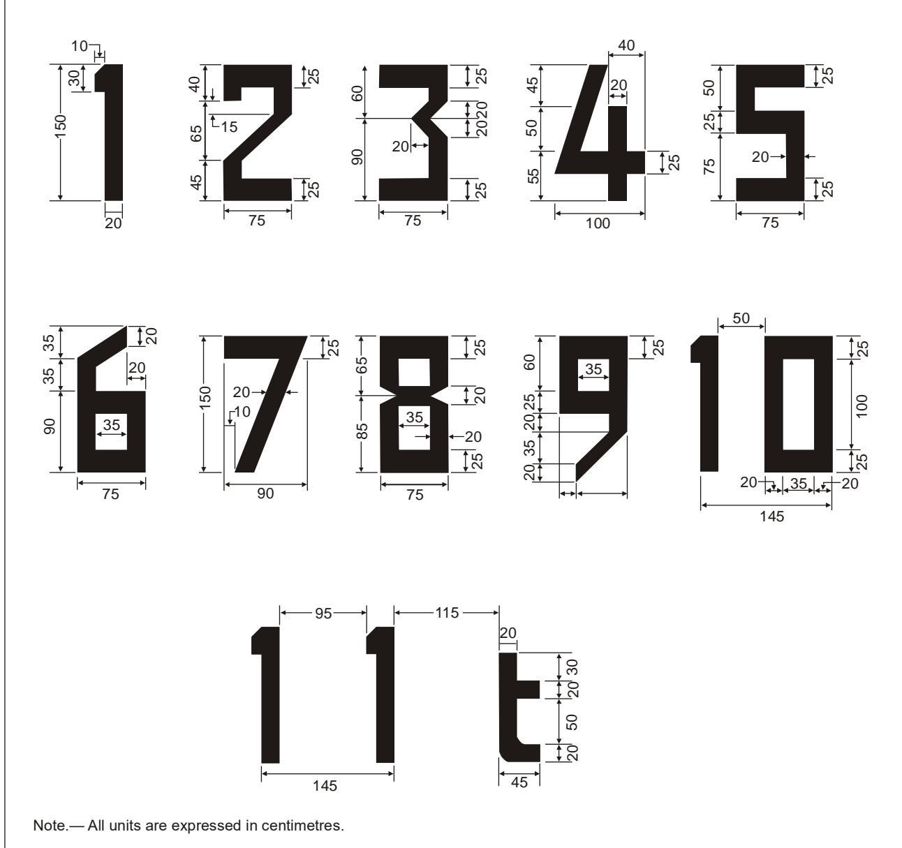
Figure E-6. Form and proportions of numbers and letters

<table><tr><td colspan="2">PTS VPT-DSN.E.550D-value marking</td></tr><tr><td colspan="2"></td></tr><tr><td colspan="2">Rationale Only metric units are employed for maximum allowable mass marking and D-value marking.</td></tr><tr><td>1. 2.</td><td>Imperial units are not used in the EU. The D-value is applicable only when required, to avoid proliferation of markings in the FATO; the distinctions between vertiports that are elevated and surface level vertiports have been eliminated to avoid duplication.</td></tr></table>

(a) The objective of D-value marking is to provide the pilot with the ‘D’ of the largest VTOL aircraft that can be accommodated on the vertiport. This value may differ in size from the FATO and the TLOF provided in compliance with Chapter C.

(b) The D-value is not required to be marked on a vertiport with a runway-type FATO.

## (c) Applicability

Where appropriate, a D-value marking should be displayed at a vertiport.

## (d) Location

(1) A D-value marking should be located within the TLOF or FATO and so arranged as to be readable from the preferred final approach direction.

(2) Where there is more than one approach direction, additional D-value markings should be provided such that at least one D-value marking is readable from the final approach direction.

## (e) Characteristics

(1) The D-value marking should be white. The D-value marking should be rounded to the nearest whole metre with 0.5 rounded down.

(2) Where the D-value marking is located within a TLOF or TDPC, it should represent the D of the largest VTOL aircraft admitted, regardless of the configuration and dimensions of the VTOL aircraft during taxiing $( \mathsf { D } _ { \mathtt { t a x i } } )$ or parking $( { \sf D } _ { \sf p a r k i n g } )$

(2) The numbers of the marking should have a colour contrasting with the background and should be in the form and proportion shown in Figure E-6 for a D-value of more than 30 m. For a D-value between 15 m and 30 m, the height of the numbers of the marking should be a minimum of 90 cm, and for a D-value of less than 15 m, the height of the numbers of the marking should be a minimum of 60 cm, each with a proportional reduction in width and thickness.

## PTS VPT-DSN.E.560 FATO perimeter marking or markers

## Rationale

1. ICAO Annex 14 Volume II, Heliports SARPs for FATO perimeter markings apply only to surface level heliports. For vertiports, the scope is enlarged for vertiports that are elevated, as there are projects containing whole-size solid FATOs that may require marking. However, there could be non-solid FATOs that would not require perimeter markings.

2. Markers are kept as useful visual aids for unpaved vertiports.

3. The VTOL-capable aircraft may change configuration for taxiing and parking, and this has been reflected in the specifications.

4. The reference to helidecks or shipboard vertiports (offshore) has been eliminated.

(a) The objective of FATO perimeter marking or markers is to provide the pilot, where the perimeter of the FATO is not self-evident, with an indication of the area that is free of obstacles, and in which intended procedures or permitted manoeuvring may take place.

## (b) Applicability

FATO perimeter marking or markers should be provided at a vertiport where the extent of a FATO with a solid surface is not self-evident.

## (c) Location

The FATO perimeter marking or markers should be located on the edge of the FATO.

## (d) Characteristics — runway-type FATOs

(1) The perimeter of the FATO should be defined with markings or markers spaced at equal intervals of not more than 50 m with at least three markings or markers on each side including a marking or marker at each corner.

(2) A FATO perimeter marking should be a rectangular stripe with a length of 9 m or one-fifth of the side of the FATO which it defines and a width of 1 m.

(3) FATO perimeter markings should be white.

(4) A FATO perimeter marker should have dimensional characteristics as shown in Figure E-7.

(5) FATO perimeter markers should be of colour(s) that contrast effectively against the operating background.

(6) FATO perimeter markers should be a single colour, orange or red, or two contrasting colours, orange and white or, alternatively, red and white should be used except where such colours would merge with the background.

## (e) Characteristics — all FATOs except runway-type FATOs

(1) For an unpaved FATO, the perimeter should be defined with flush in-ground markers. The FATO perimeter markers should be 30 cm in width, 1.5 m in length, and with end-to-end spacing of not less than 1.5 m and not more than 2 m. The corners of a square or rectangular FATO shall be defined.

(2) For a paved FATO, the perimeter should be defined with a dashed line. The FATO perimeter marking segments should be 30 cm in width, 1.5 m in length, and with end-toend spacing of not less than 1.5 m and not more than 2 m. The corners of the square or rectangular FATO should be defined.

(3) FATO perimeter markings and flush in-ground markers should be white.

![279a85674ef789421fd038fdb5fdbec23db2e8cd9a4077cde8446ef984bd9ccc.jpg](https://aam-wiki.gksj.cc/uploads/images/gallery/2026-05/scaled-1680-/279a85674ef789421fd038fdb5fdbec23db2e8cd9a4077cde8446ef984bd9ccc.jpg)  
Figure E-7. Runway-type FATO edge marker

PTS VPT-DSN.E.570 FATO designation markings for runway-type FATOs

<table><tr><td>Rationale</td></tr><tr><td>The text has been transposed from ICAO, Annex 14, Volume I, Heliports.</td></tr></table>

(a) The objective of FATO designation markings for runway-type FATOs is to provide the pilot with an indication of the magnetic heading of the runway.

## (b) Applicability

A FATO designation marking should be provided at a vertiport where it is necessary to designate the FATO to the pilot.

## (c) Location

A FATO designation marking should be located at the beginning of the FATO as shown in Figure E-3.

## (d) Characteristics

A FATO designation marking should consist of a two-digit number. The two-digit number should be the whole number nearest to one-tenth of the magnetic North when viewed from the direction of approach. When this rule would give a single-digit number, it should be preceded by a zero. The marking, as shown in Figure E-3, should be supplemented by the vertiport identification marking ‘V’.

## PTS VPT-DSN.E.580 Aiming point marking

## Rationale

It may be required to develop visual aids for obstacle-free volume FATOs after input from manufacturers on the performance of VTOL-capable aircraft is received.

2. Possible confusion of the aiming point marking with the vertiport identification marking is avoided due to the blue circle surrounding the ‘V’.

(a) The objective of the aiming point marking is to provide the pilot with a visual cue indicating the preferred approach/departure direction, the point to which the aircraft with VTOL capability approaches to the hover before positioning to a stand where a touchdown can be made, and that the surface of the FATO is not intended for touchdown.

(b) The aiming point marking is not required to be marked on FATOs elevated over the surface of the vertiport or obstacle-free volume FATOs.

## (c) Applicability

An aiming point marking should be provided at a vertiport where it is necessary for a pilot to make an approach to a particular point above a FATO before proceeding to a TLOF.

## (d) Location — runway-type FATOs

The aiming point marking should be located within the FATO.

## (e) Location — all FATOs except runway-type FATOs

The aiming point marking should be located at the centre of the FATO as shown in Figure E-1.

## (f) Characteristics

The aiming point marking should be an equilateral triangle with the bisector of one of the angles aligned with the preferred approach direction. The marking should consist of continuous lines providing a contrast with the background colour, and the dimensions of the marking should conform to those shown in Figure E-8.

![0c42d164214a8827d494a3dff0730d9c2638d0cd11e218cbd7e9a55327d4de64.jpg](https://aam-wiki.gksj.cc/uploads/images/gallery/2026-05/scaled-1680-/0c42d164214a8827d494a3dff0730d9c2638d0cd11e218cbd7e9a55327d4de64.jpg)  
Figure E-8. Aiming point marking

## PTS VPT-DSN.E.590 TLOF perimeter marking

## Rationale

1. TLOF perimeter markings should always be displayed at vertiports that are elevated, but only on surface level vertiports if the perimeter is not self-evident.

2. The reference to helidecks or shipboard vertiports (offshore) has been eliminated.

(a) The objective of a TLOF perimeter marking is to provide the pilot with an indication of an area that is free of obstacles; has dynamic load bearing; and in which, when positioned in accordance with the TDPM, undercarriage containment is assured.

## (b) Applicability:

(1) A TLOF perimeter marking should be displayed on a TLOF located within a FATO at a surface-level vertiport if the perimeter of the TLOF is not self-evident.

(2) A TLOF perimeter marking should be displayed on a vertiport that is elevated.

## (c) Location

A TLOF perimeter marking should be located along the edge of the TLOF.

## (d) Characteristics

A TLOF perimeter marking should consist of a continuous white line with a width of at least 30 cm.

## PTS VPT-DSN.E.600 Touchdown positioning marking (TDPM)

## Rationale

1 The usefulness of TDPM for VTOL-capable aircraft should be evaluated after input from manufacturers, including distinction between circular and shoulder ones.

2. The prohibited landing sector marking for helidecks (offshore) has been eliminated.

(a) The objective of TDPM is to provide visual cues which permit a VTOL-capable aircraft to be placed in a specific position such that, when the pilot’s seat is above the marking, the undercarriage is within the load-bearing area and all parts of the VTOL-capable aircraft will be clear of any obstacles by a safe margin.

## (b) Applicability

(1) A TDPM should be provided for a VTOL-capable aircraft to touchdown or be accurately placed in a specific position.

(2) The TDPM should be:

(i) when there is no limitation on the direction of touchdown/positioning, a touchdown/positioning circle (TDPC) marking; and

(ii) when there is a limitation on the direction of touchdown/positioning in the form of unidirectional applications, a shoulder line with an associated centre line.

## (c) Location

The inner edge/inner circumference of the TDPM should be at a distance of 0.25 D from the centre of the area in which the VTOL-capable aircraft is to be positioned.

## (d) Characteristics

(1) The inner diameter of the TDPC should be 0.5 D of the largest VTOL-capable aircraft the area is intended to serve.

(2) A TDPM should have a line with a width of at least 0.5 m.

(3) The length of a shoulder line should be 0.5 D of the largest VTOL-capable aircraft the area is intended to serve.

(4) The TDPM should take precedence when used in conjunction with other markings on the TLOF.

![58ea5a3da2228e38d4822d7e8ea4ec5d54ff9ce57b8b49c5cb59c521ee3dd504.jpg](https://aam-wiki.gksj.cc/uploads/images/gallery/2026-05/scaled-1680-/58ea5a3da2228e38d4822d7e8ea4ec5d54ff9ce57b8b49c5cb59c521ee3dd504.jpg)

![0f28458dd5296638233d98b2dd04d99c91f30763838d0446175bcd1aa7e7d32a.jpg](https://aam-wiki.gksj.cc/uploads/images/gallery/2026-05/scaled-1680-/0f28458dd5296638233d98b2dd04d99c91f30763838d0446175bcd1aa7e7d32a.jpg)

![c0fdd745497fd9ea8acc3def3476a9f0ac8b1308438f86e354cd4ff9a68b2936.jpg](https://aam-wiki.gksj.cc/uploads/images/gallery/2026-05/scaled-1680-/c0fdd745497fd9ea8acc3def3476a9f0ac8b1308438f86e354cd4ff9a68b2936.jpg)  
Figure E-9. Multidirectional TDPC with no limitations (left)

Unidirectional marking shoulder line with associated centre line (centre)

## PTS VPT-DSN.E.610 Obstacle sector marking

## Rationale

1. The omnidirectional obstacle-free volume may have sectors with obstacles that cannot be used for take-off and landing of the VTOL-capable aircraft. To provide the pilots with an indication of those sectors, a new marking is devised based on the prohibited landing sector marking of the helidecks.

2. The proposed name is obstacle sector marking and it will be white and red chequered instead of hatched, to differentiate it from the prohibited landing sector marking of the helidecks

3. While, according to the Heliport Manual, the prohibited landing sector marking is used where it is necessary to protect the helicopter from landing or manoeuvring in close proximity to obstacles that may affect the tail rotor beyond the view of the air crew, by marking the sector where the nose of the helicopter should not be placed, the obstacle sector marking is devised to avoid take-off and landing of the VTOL-capable aircraft in the marked sector due to the presence of obstacles in the omnidirectional obstacle-free volume inside the sector.

4. The marking is not intended to mark objects in the SA or in the protected side slope.

(a) The objective of obstacle sector marking is to provide the pilot with an indication of the sector of an omnidirectional obstacle-free volume that should not be used for take-off and landing due to the presence of obstacles above the revolution obstacle-free volume. The obstacle sector marking is not intended to indicate objects in the SA or in the protected side slope of the FATO.

## (b) Applicability

An obstacle sector marking should be provided at a vertiport where there are obstacles above the omnidirectional obstacle-free volume that cannot be removed.

## (c) Location

Obstacle sector markings should be located at the edge of the vertiport identification marking or on the TDPM if it is provided, within the relevant headings, and extend to the inner edge of the FATO.

## (d) Characteristics

(1) The prohibited sector marking should be indicated by white and red chequered markings as shown in Figure E-9.

(2) FATO, TLOF TDPM and vertiport identification markings shall take precedence over obstacle sector markings.

(3) The arc of coverage of the obstacle sector marking should be sufficient to ensure a lateral separation between the VTOL-capable aircraft and the obstacle of 3.5 D for day operations and 5 D for night operations, when the VTOL-capable aircraft lands or takes off clear of the obstacle sector marking.

## PTS VPT-DSN.E.620 Vertiport name marking

## Rationale

1. No location specification is given in ICAO Annex 14, Volume II for name markings in vertiports others than helidecks and shipboard heliports. Thus, a new text allowing maximum flexibility is provided.

2. The reference to helidecks or shipboard vertiports (offshore) has been eliminated.

(a) The objective of vertiport name marking is to provide the pilot with a means of identifying a vertiport which can be seen, and read, from all directions of approach.

## (b) Applicability

A vertiport name marking should be provided at a vertiport where there is insufficient alternative means of visual identification.

## (b) Location

The vertiport name marking should be located at a position such as it can be seen and read from all directions of approach.

## (c) Characteristics

(1) A vertiport name marking should consist of the name or the alphanumeric designator of the vertiport as used in the radio (R/T) communications.

(2) A vertiport name marking intended for use at night or during conditions of poor visibility should be illuminated, either internally or externally.

(3) Runway-type FATOs: The characters of the marking should be not less than 3 m in height.

(4) All FATOs except runway-type FATOs: The characters of the marking should be not less than 1.5 m in height at surface-level vertiports and not less than 1.2 m on vertiports that are elevated. The colour of the marking should contrast with the background and preferably be white.

## PTS VPT-DSN.E.630 VTOL-capable aircraft taxiway markings and markers

## Rationale

1. The ICAO Annex 14, Volume II note on the applicability of runway position markings of ICAO Annex 14, Volume I has been kept changing reference for aerodrome Certification Specifications. Holding position markings can be useful for vertiports.

2. Taxiways have been considered suitable for VTOL-capable aircraft taxiing by means of ground movement equipment.

3. Markers have been kept for their usefulness for unpaved taxiways. Location distances have been considered enough to provide clearance for VTOL-capable aircraft (in line with Chapter C clearances for stands) but may need to be reconsidered after input from manufacturers.

4. Guidance on taxiway edge markers from the Heliport Manual has been included along with a new figure.

5. The term ‘frangible to the wheeled undercarriage of a helicopter’ has been replaced with ‘frangible to the wheeled undercarriage of a VTOL-capable aircraft’.

(a) The objective of VTOL-capable aircraft taxiway markings and markers is, without being a hazard to the VTOL-capable aircraft, to provide the pilot by day and, if necessary, by night, with visual cues to guide movement along the taxiway.

(b) The specifications for runway-holding position markings in certification specifications for aerodrome design, CS ADR-DSN.L.575, are equally applicable as guidance material to taxiways intended for ground taxiing of VTOL-capable aircraft.

(c) Ground taxi-routes and air taxi-routes over a taxiway are not required to be marked.

(d) Unless otherwise indicated, it may be assumed that a VTOL-capable aircraft taxiway is suitable for ground taxiing, air taxiing and taxiing by means of ground movement equipment of VTOLcapable aircraft.

(e) Signage may be required on an aerodrome where it is necessary to indicate that a VTOL-capable aircraft taxiway is suitable only for the use of VTOL-capable aircraft.

## (f) Applicability

(1) The centre line of a VTOL-capable aircraft taxiway should be identified with a marking.

(2) The edges of a VTOL-capable aircraft taxiway, if not self-evident, should be identified with markers or markings.

## (g) Location

(1) VTOL-capable aircraft taxiway markings should be along the centre line and, if required, along the edges of a VTOL-capable aircraft taxiway.

(2) VTOL-capable aircraft taxiway edge markers should be located at a distance of 1 m to 3 m beyond the edge of the VTOL-capable aircraft taxiway.

(3) VTOL-capable aircraft taxiway edge markers should be spaced at intervals of not more than 15 m on each side of straight sections and 7.5 m on each side of curved sections with a minimum of four equally spaced markers per section.

## (h) Characteristics

(1) On a paved taxiway, a VTOL-capable aircraft taxiway centre line marking should be a continuous yellow line 15 cm in width.

(2) On an unpaved taxiway that will not accommodate painted markings, a VTOL-capable aircraft taxiway centre line should be marked with flush in-ground 15-cm-wide and approximately 1.5 m in length yellow markers, spaced at intervals of not more than 30 m on straight sections and not more than 15 m on curves, with a minimum of four equally spaced markers per section.

(3) VTOL-capable aircraft taxiway edge markings should be a continuous double yellow line, each 15 cm in width, and spaced 15 cm apart (nearest edge to nearest edge).

(4) A VTOL-capable aircraft taxiway edge marker should be lightweight and frangible to the undercarriage of a VTOL-capable aircraft.

(4) A VTOL-capable aircraft taxiway edge marker should not exceed a plane originating at a height of 25 cm above the plane of the VTOL-capable aircraft taxiway, at a distance of 0.5 m from the edge of the VTOL-capable aircraft taxiway and sloping upwards and outwards at a gradient of 5 per cent to a distance of 3 m beyond the edge of the VTOLcapable aircraft taxiway.

(5) A VTOL-capable aircraft taxiway edge marker should be blue.

Note: If blue markers are used on an aerodrome, signage may be required to indicate that the VTOL-capable aircraft taxiway is suitable only for VTOL-capable aircraft.

(6) If the VTOL-capable aircraft taxiway is to be used at night, the edge markers should be internally illuminated or retroreflective.

(7) The marked surface of the marker, as seen by the pilot, should be a rectangle and have a minimum viewing area of 150 cm2, as shown in Figure E-10. Markers commonly used are cylindrical in shape.

![c81a35170609714d6e8f65fc77527a5a7f7347aac976dc96123ddb9fe8dec6c2.jpg](https://aam-wiki.gksj.cc/uploads/images/gallery/2026-05/scaled-1680-/c81a35170609714d6e8f65fc77527a5a7f7347aac976dc96123ddb9fe8dec6c2.jpg)  
Figure E-10. VTOL-capable aircraft taxiway edge marker

## PTS VPT-DSN.E.640 VTOL-capable aircraft air taxi-route markings and markers

## Rationale

1. The markers have been kept for their usefulness for unpaved air taxi-routes.

2. Guidance from the Heliport Manual has been included, and the Characteristics section has been restructured. The air taxi-route markers of the Heliport manual are not flush in ground. The specifications of ICAO Annex 14, Volume II are kept with flush in-ground markers, and the figure of the Heliport Manual has been adapted to show flush in ground markers.

(a) The objective of VTOL-capable aircraft air taxi-route markings and markers is to provide the pilot by day and, if necessary, by night, with visual cues to guide movement along the air taxiroute.

## (b) Applicability

The centre line of a VTOL-capable aircraft air taxi-route should be identified with markers or markings.

## (c) Location

A VTOL-capable aircraft air taxi-route centre line marking or flush in-ground centre line marker should be located along the centre line of the VTOL aircraft air taxi-route.

## (d) Characteristics

(1) Where an air taxi-route is collocated with a taxiway, the centre line markings will be those of the taxiway.

(2) Where an air taxi-route is not collocated with a taxiway:

(i) when on a paved surface, the air taxi-route centre line should be marked with a continuous yellow line 15 cm in width;

(ii) when on an unpaved surface that will not accommodate painted markings, the air taxi-route centre line should be marked with flush in-ground 15 cm-wide and approximately 1.5 m in length yellow markers, spaced at intervals of not more than 30 m on straight sections and not more than 15 m on curves, with a minimum of four equally spaced markers per section.

(3) If the VTOL-capable aircraft air taxi-route is to be used at night, markers should be either internally illuminated or retroreflective.

![ebace090decd849bbbad7bc63d5814ad1490ede0edfab6e5f99f0da7de97516b.jpg](https://aam-wiki.gksj.cc/uploads/images/gallery/2026-05/scaled-1680-/ebace090decd849bbbad7bc63d5814ad1490ede0edfab6e5f99f0da7de97516b.jpg)  
Figure E-11. Air taxi route marker

## PTS VPT-DSN.E.650 VTOL-capable aircraft stand markings

## Rationale

1. Consideration has been given to the design of stands according to Chapter C (PTS HPT-DSN.C.310), where two types of stands have been designed: the D-value-based stand and the geometry-based stand. For the latter stand, perimeter lines may not be provided if the aircraft is not under its own power (towed or on ground movement equipment and clearances can be assured with the use of alignment lines).

2. The dimensions of stands designed like helicopter stands may need to be revised after input from the manufacturers.

3. Guidance from the Heliport Manual has been included.

(a) The objective of VTOL-capable aircraft stand markings is to provide the pilot with a visual indication of: an area that is free of obstacles and in which manoeuvring is permitted, and all necessary ground functions, may take place: identification, mass and D-value limitations, when required; and guidance for manoeuvring and positioning of the VTOL-capable aircraft within the stand.

(b) VTOL-capable aircraft stand identification markings may be provided where there is a need to identify individual stands.

(c) See PTS VPT-DSN.E.590, PTS VPT-DSN.E.600 and Figure E-13 regarding TLOF perimeter markings, TDPMs and lead-in/lead-out lines.

## (d) Applicability

(1) A VTOL-capable aircraft stand perimeter marking should be provided when the stand is designed according to PTS VPT-DSN.C.320 (e)(1) and (e)(2).

(2) A VTOL aircraft stand perimeter marking should be provided when the stand is designed according to PTS VPT-DSN.C.320 (g) and (h), except when the aircraft enters and exits the stand not under its own power and the clearance distances can be assured with the use of alignment and lead-in/lead-out lines.

(2) A VTOL-capable aircraft stand should be provided with the appropriate TDPM, see Figure E-13.

(3) If appropriate, alignment lines and lead-in/lead-out lines should be provided on a VTOLcapable aircraft stand, see Figure E-13.

(4) Where the stand is designed to accommodate VTOL-capable aircraft with a D smaller than the Design-D, a box containing the limiting D-value should be displayed on the lead-in line. See Figure E-12. A box containing the maximum allowable mass may be added if required.

![ccdef646b53cd3822f23d54511b2374d3cabf02fc6db7ebf6356c7f9597937d2.jpg](https://aam-wiki.gksj.cc/uploads/images/gallery/2026-05/scaled-1680-/ccdef646b53cd3822f23d54511b2374d3cabf02fc6db7ebf6356c7f9597937d2.jpg)  
Figure E-12. Restricted-size stand

(e) Location

(1) The TDPM, alignment lines and lead-in/lead-out lines should be located such that every part of the VTOL-capable aircraft can be contained within the VTOL-capable aircraft stand during positioning and permitted manoeuvring.

(2) Alignment lines and lead-in/lead-out lines should be located as shown in Figure E-13.

## (f) Characteristics

(1) A VTOL-capable aircraft stand perimeter marking should consist of a continuous yellow line and have a line width of 15 cm.

(2) The TDPM should have the characteristics described in PTS VPT-DSN.E.600 above.

(3) Alignment lines and lead-in/lead-out lines should be continuous yellow lines and have a width of 15 cm. Where it is intended that VTOL-capable aircraft proceed in one direction only, arrows indicating the direction to be followed may be added as part of the alignment lines, see Figure E-13.

(4) Curved portions of alignment lines and lead-in/lead-out lines should have radii appropriate to the most demanding VTOL-capable aircraft type the stand is intended to serve.

Note: The most demanding VTOL-capable aircraft in terms of turning radius may be different from the most demanding VTOL-capable aircraft in terms of D-value.

(5) Stand identification markings should be marked in a contrasting colour so as to be easily readable.

(6) When unpaved, the stand perimeter should be marked with flush in-ground markers.

![a391875ab803118f2f632ec7e8cb64be17869b8db56cee205e125faf41890a8e.jpg](https://aam-wiki.gksj.cc/uploads/images/gallery/2026-05/scaled-1680-/a391875ab803118f2f632ec7e8cb64be17869b8db56cee205e125faf41890a8e.jpg)  
Figure E-13. VTOL-capable aircraft stand markings

## PTS VPT-DSN.E.660 Apron safety lines

<table><tr><td>Rationale</td></tr><tr><td>1. Text has been added from CS ADR-DSN.L.595 to provide markings for parking and handling. 2. Guidance from GM1 ADR-DSN.L.595, Apron safety lines, has been included.</td></tr></table>

(a) The objective of the apron safety lines is to mark the limits of VTOL-capable aircraft clearance lines, parking areas for ground equipment, apron service roads and passengers’ paths.

(1) VTOL-capable aircraft clearance lines are used to delineate the safety zone clear of the path of the critical VTOL-capable aircraft.

(2) Equipment limit lines are used to indicate the limits of areas which are intended for parking vehicles and aircraft servicing equipment when they are not in use.

(3) Passenger path lines are used to keep passengers, when walking on the apron, clear of hazards.

## (e) Applicability

Apron safety lines should be provided on an apron as required by the parking configurations and ground facilities.

## (f) Location

Apron safety lines should be located so as to define the areas intended for use by ground vehicles and other aircraft servicing equipment, passengers and pedestrians, etc., to provide safe separation from VTOL aircraft.

## (g) Characteristics

(1) Apron safety lines should include such elements as VTOL-capable aircraft clearance lines and service road boundary lines as required by the parking configurations and ground facilities.

(2) Apron safety lines should be of a conspicuous colour, preferably red, which should contrast with that used for VTOL-capable aircraft stand markings.

(3) An apron safety line should be continuous in length and at least 10 cm in width.

## PTS VPT-DSN.E.670 Flight path alignment guidance marking

<table><tr><td>Rationale</td></tr><tr><td>ICAO Annex 14, Volume II text has been transposed with no changes.</td></tr></table>

(a) The objective of flight path alignment guidance marking is to provide the pilot with a visual indication of the available approach and/or departure path direction(s).

(b) The flight path alignment guidance marking can be combined with a flight path alignment guidance lighting system as described in PTS VPT-DSN.E.730.

## (c) Applicability

Flight path alignment guidance marking(s) should be provided at a vertiport where it is desirable and practicable to indicate available approach and/or departure path direction(s).

## (d) Location

The flight path alignment guidance marking should be located in a straight line along the direction of approach and/or departure path on one or more of the TLOF, FATO, SA or any other suitable surface in the immediate vicinity of the FATO or SA.

## (e) Characteristics

(1) A flight path alignment guidance marking should consist of one or more arrows marked on the TLOF, FATO and/or SA surface as shown in Figure E-14. The stroke of the arrow(s) shall be 50 cm in width and at least 3 m in length. When combined with a flight path alignment guidance lighting system, it should take the form shown in Figure E-14 which includes the scheme for marking ‘heads of the arrows’ which are constant regardless of stroke length.

(2) In the case of a flight path limited to a single approach direction or single departure direction, the arrow marking may be unidirectional. In the case of a vertiport with only a single approach/departure path available, one bidirectional arrow is marked.

(3) The markings should be in a colour which provides good contrast against the background colour of the surface on which they are marked, preferably white.

![d7979356c1e3cd7a9b3dc4aa27dc156ad522558cfd87562c7bd7ab21d26217eb.jpg](https://aam-wiki.gksj.cc/uploads/images/gallery/2026-05/scaled-1680-/d7979356c1e3cd7a9b3dc4aa27dc156ad522558cfd87562c7bd7ab21d26217eb.jpg)  
Figure E-14. Flight path alignment guidance markings and lights

## PTS VPT-DSN.E.680 Visual aids for denoting restricted-use areas

## Rationale

1. Text has been added from CS ADR-DSN.R.855 and CS ADR-DSN.R.870, as well as from their associated GM, to provide markings for restricted-use areas.

2. Non-load-bearing surface markings have not been included as they are already in the taxiway markings section. The pre-threshold area has not been included as it is not applicable.

(a) The objective of the markings and lights for denoting closed areas is to provide the pilot with an indication of FATOs, TLOFs, stands, taxiways or portion of taxiways that are closed.

(b) The objective of the unserviceability markers and lights is to warn the pilots of a hole in a taxiway or apron pavement, or to outline for the pilots a portion of pavement, such as on an apron or a taxiway, that is under repair. They are not suitable for use when a FATO, a TLOF, a stand or a taxiway becomes unserviceable. In such instances, the FATO, TLOF, stand or taxiway is normally closed.

## (c) Applicability — closed markings

(1) A closed marking should be displayed on a FATO, TLOF, stand, taxiway or portion of taxiway which is permanently closed to the use of all aircraft.

(2) A closed marking should be displayed on a temporarily closed FATO, TLOF, stand, taxiway or portion of taxiway, except that such marking may be omitted when the closing is of short duration and adequate warning by air traffic services is provided.

## (d) Location — closed markings

(1) On a runway-type FATO, a closed marking should be placed at each end of the FATO.

(2) On a FATO other than a runway-type FATO, a closed marking should be placed at the centre of the FATO.

(3) On a taxiway, a closed marking should be placed at least at each end of the taxiway or portion thereof closed.

(4) On a TLOF, a closed marking should be placed at the centre of the TLOF.

(5) On a stand, a closed marking should be placed at the centre of the stand.

## (e) Characteristics — closed markings

(1) The closed marking should be of the form of a letter ‘X’. See Figure E-15. The width of the strokes should be 1,5 m. When displayed on a FATO, the length of the strokes will extend at a distance of 15 cm of the FATO perimeter marking. When displayed on a taxiway, the length of the strokes will extend at a distance of 15 cm of the edge of the taxiway. The marking shall be white when displayed on a FATO and shall be yellow when displayed on a taxiway.

(2) When a FATO, TLOF, stand, taxiway or portion of taxiway is permanently closed, all normal FATO, TLOF, stand, taxiway markings should be physically removed.

(3) Lighting on a closed FATO, TLOF, stand, taxiway or portion of taxiway should not be operated, except as required for maintenance purposes.

(4) In addition to closed markings, when the taxiway or portion thereof that is closed is intercepted by a usable taxiway which is used at night, unserviceability lights should be placed across the entrance to the closed area with a minimum of three lights at intervals not exceeding 3 m.

## (f) Applicability — unserviceable areas

Unserviceability markers should be displayed wherever any portion of a taxiway or apron is unfit for the movement of VTOL-capable aircraft, but it is still possible for VTOL-capable aircraft to bypass the area safely. On a movement area used at night, unserviceability lights shall be used.

## (g) Location — unserviceable areas

Unserviceability markers and lights should be placed at intervals sufficiently close so as to delineate the unserviceable area.

## (h) Characteristics of unserviceability markers

(1) Unserviceability markers should consist of conspicuous upstanding devices such as cones or marker boards.

(2) An unserviceability cone should be of a height that does not interfere with parts of the VTOL-capable aircraft and red, orange or yellow in combination with white.

(3) An unserviceability marker board should be of a height that does not interfere with parts of the VTOL-capable aircraft and 0.6 m in length, with alternate red and white or orange and white vertical stripes.

## (i) Characteristics of unserviceability lights

An unserviceability light should consist of a red fixed light. The light should have an intensity sufficient to ensure conspicuity considering the intensity of the adjacent lights and the general level of illumination against which it would normally be viewed. In no case should the intensity be less than 10 cd of red light.

![f70b5e1499c9d8ba1ad91b67a2deed51cbdbe1adfc954792023595a74e71ce34.jpg](https://aam-wiki.gksj.cc/uploads/images/gallery/2026-05/scaled-1680-/f70b5e1499c9d8ba1ad91b67a2deed51cbdbe1adfc954792023595a74e71ce34.jpg)  
Figure E-15. Closed FATO, TLOF, stand or taxiway marking

## PTS VPT-DSN.E.700 Lights — general

(a) The technical specifications for the lights address issues for VTOL-capable aircraft operations at night:

(1) distinguishing one defined area from another;

(2) providing conspicuity for acquiring visual contact with the vertiport;

(3) providing guidance in the approach and departure phases of flight; and

(4) providing visual cues to allow accurate manoeuvring and placement of the VTOL-capable aircraft when within the bounds of the vertiport.

(b) Lights and lighting systems installed at vertiports should be dimmable in order to reduce intensity, if needed.

Note 1: See ICAO Annex 14, Volume I, 5.3.1, concerning specifications on screening of nonaeronautical ground lights, and design of elevated and inset lights.

Note 2: In the case of vertiports located near navigable waters, consideration needs to be given to ensuring that aeronautical ground lights do not cause confusion to mariners.

Note 3: As VTOL-capable aircraft will generally come very close to extraneous light sources, it is particularly important to ensure that, unless such lights are navigation lights exhibited in accordance with international regulations, they are screened or located so as to avoid direct and reflected glare.

Note 4: Systems addressed in paragraphs PTS-VPT-DSN E.730, E.750, E760 and E.770 are designed to provide effective lighting cues based on night conditions. Where lights are to be used in conditions other than night (i.e. day or twilight), it may be necessary to increase the intensity of the lighting to maintain effective visual cues by use of a suitable brilliancy control.

Note 5: The specifications for marking and lighting of obstacles included in Annex 14, Volume I, Chapter 6, are equally applicable to vertiports.

Note 6: In cases where operations into a vertiport are to be conducted at night with night vision imaging systems (NVIS), it is important to establish the compatibility of the NVIS with all vertiport lighting through an assessment by the VTOL-capable aircraft operator prior to use.

Further guidance on lights is given in ICAO Doc 9157, Aerodrome Design Manual, Part 4 – Visual aids and Document 9261, Heliport Manual.

## PTS VPT-DSN.E.710 Vertiport beacon

(a) The objective of the vertiport beacon is to provide, when necessary, a long-range visual guidance and when not provided by other visual means, or when identifying the vertiport is difficult due to surrounding lights.

## (b) Applicability

Where provided, a vertiport beacon should be located at a vertiport where:

(1) long-range visual guidance is considered necessary and is not provided by other visual means; or

(2) identification of the vertiport is difficult due to surrounding lights.

## (c) Location

The vertiport beacon should be located on or adjacent to the vertiport preferably at an elevated position and so that it does not dazzle a pilot at short range.

Note: Where a vertiport beacon is likely to dazzle pilots at short range, it may be switched off during the final stages of the approach and landing.

## (d) Characteristics

(1) The vertiport beacon should emit repeated series of equally spaced short-duration white flashes in the format shown in Figure E-16.

![a21ca740e40f177a2bd66e34517ae3417c0b5e0cf3919f615bf0550cff515fd6.jpg](https://aam-wiki.gksj.cc/uploads/images/gallery/2026-05/scaled-1680-/a21ca740e40f177a2bd66e34517ae3417c0b5e0cf3919f615bf0550cff515fd6.jpg)  
Figure E-16. Vertiport beacon flash characteristics

(2) The light from the beacon should show at all angles of azimuth. To ensure that pilots are not dazzled during the final stages of the approach and landing, especially at night, brilliancy control (with 10 per cent and 3 per cent settings) or shielding should be provided.

(3) The effective light intensity distribution of each flash should be as shown in Figure E-19, Illustration 1.

## PTS VPT-DSN.E.720 Approach lighting system

(a) The objective of an approach lighting system is to provide an indication of the preferred approach direction to enhance the closure rate information to pilots at night.

## (b) Applicability

Where provided, an approach lighting system should indicate a preferred approach direction.

## (c) Location

The approach lighting system should be located in a straight line along the preferred approach direction.

## (d) Characteristics

(1) An approach lighting system should consist of a row of three lights spaced uniformly at 30 m intervals and of a crossbar 18 m in length at a distance of 90 m from the perimeter of the FATO as shown in Figure E-17 and Figure E-18. The lights forming the crossbar should be as nearly as practicable in a horizontal straight line at right angles to, and bisected by, the line of the centre line lights and spaced at 4.5 m intervals. Where there is the need to make the final approach course more conspicuous, additional lights spaced uniformly at 30 m intervals should be added beyond the crossbar. The lights beyond the crossbar may be steady or sequenced flashing, depending upon the environment.

(2) Sequenced flashing lights may be provided where identification of the approach lighting system is difficult due to surrounding lights.

(3) The lights should be omnidirectional steady white lights except that beyond the crossbar either omnidirectional steady or flashing white lights may be used.

![87ae1a64cebfce0d94b621d3c519a6050ef03e487f620e4c91e90ed643822c83.jpg](https://aam-wiki.gksj.cc/uploads/images/gallery/2026-05/scaled-1680-/87ae1a64cebfce0d94b621d3c519a6050ef03e487f620e4c91e90ed643822c83.jpg)  
Figure E-17. Approach lighting system

(4) The flashing lights should have a flash frequency of one per second and their light distribution should be as shown in Figure E-19, Illustration 3. The flash sequence should commence from the outermost light and progress towards the crossbar.

(5) A suitable brilliancy control should be incorporated to allow for adjustment of light intensity to meet the prevailing conditions.

(6) The following intensity settings should be provided:

steady lights — 100 per cent, 30 per cent and 10 per cent; and

flashing lights — 100 per cent, 10 per cent and 3 per cent.

![b983b709f48d3f300bdf46d6da99fdfd4fcb05072610fe8382e1392dcc425d42.jpg](https://aam-wiki.gksj.cc/uploads/images/gallery/2026-05/scaled-1680-/b983b709f48d3f300bdf46d6da99fdfd4fcb05072610fe8382e1392dcc425d42.jpg)  
Figure E-18. Two different configurations of an approach lighting system

![3aeb9927756884b24e704d9b7f5a6f50696e1fd48134e8ba0cb9fad04e70440e.jpg](https://aam-wiki.gksj.cc/uploads/images/gallery/2026-05/scaled-1680-/3aeb9927756884b24e704d9b7f5a6f50696e1fd48134e8ba0cb9fad04e70440e.jpg)  
Figure E-19. Isocandela diagrams

## PTS VPT-DSN.E.730 Flight path alignment guidance lighting system

(a) The objective of the flight path alignment guidance lighting system is to provide the pilot with a visual indication, at night, of the available approach and/or departure path directions.

## (b) Applicability

Where provided, flight path alignment guidance lighting system(s) should be installed at a vertiport to indicate available approach and/or departure path direction(s).

(c) The flight path alignment guidance lighting system can be combined with the flight path alignment guidance marking described in PTS VPT-DSN.E.670, see Figure E-14 and Figure E-20.

## (d) Location

(1) The flight path alignment guidance lighting system should be in a straight line along the direction(s) of approach and/or departure path on one or more of the TLOF, FATO, SA or any other suitable surface in the immediate vicinity of the FATO, TLOF or SA.

(2) When combined with a flight path alignment guidance marking (PTS VPT-DSN.E.670), the lights should be located inside the ‘arrow’ markings.

## (e) Characteristics

(1) A flight path alignment guidance lighting system should consist of a row of three or more lights spaced uniformly with a total minimum distance of 6 m. Intervals between lights should not be less than 1.5 m and should not exceed 3 m. Where space permits, there should be five lights, see Figure E-20.

(2) The number of lights and spacing between these lights may be adjusted to reflect the space available. If more than one flight path alignment system is used to indicate available approach and/or departure path direction(s), the characteristics for each system are typically kept the same, see Figure E-20.

(3) The lights should be steady omnidirectional inset white lights.

(4) The distribution of the lights should be as indicated in Figure E-19, Illustration 5.

(5) The system should allow an adjustment of light intensity to meet the prevailing conditions and to balance the flight path alignment guidance lighting system with other vertiport lights and general lighting that may be present around the vertiport.

![92214f7361659f421bdbc736a07924c93c869672cd498f87be4ccee91c209c0b.jpg](https://aam-wiki.gksj.cc/uploads/images/gallery/2026-05/scaled-1680-/92214f7361659f421bdbc736a07924c93c869672cd498f87be4ccee91c209c0b.jpg)  
Figure E-20. Flight path alignment guidance markings and lights

## PTS VPT-DSN.E.740 Visual alignment guidance system

(a) The objective of a visual alignment guidance system is to provide conspicuous and discrete cues to assist the pilot in attaining and maintaining a specified approach track to a vertiport and a safe lateral clearance from obstacles when on final approach.

## (b) Applicability

Where provided, a visual alignment guidance system should be installed to serve the approach to a vertiport where one or more of the following conditions exist, especially at night:

(1) obstacle clearance, noise abatement or traffic control procedures require a particular direction to be flown;

(2) the environment of the vertiport provides few visual surface cues; and

(3) it is physically impracticable to install an approach lighting system.

## (c) Location

The visual alignment guidance system should be located such that a VTOL-capable aircraft is guided along the prescribed track towards the FATO and should be placed at its downwind edge and aligned along the preferred approach direction.

## (d) Characteristics

(1) The signal of the system should be such that there is no confusion between the system and any associated visual approach slope indicator or other visual aids.

(2) The signal format should be unique and conspicuous in all operational environments for which it is intended to use the visual alignment guidance system.

(3) The system provides a minimum of three discrete signal sectors giving ‘offset to the right’, ‘on track’ and ‘offset to the left’ indications.

(4) The system should be capable of adjustment in azimuth to within ±5 minutes of arc of the desired approach track.

(5) Where the lights of the system need to be seen as discrete sources, light units should be located such that at the extremes of the system coverage the angle subtended between units as seen by the pilot should not be less than 3 minutes of arc. The angle subtended between light units of the system and other lights of comparable or greater intensity should also not be less than 3 minutes of arc. This can be met for lights on a line normal to the line of sight if they are separated by 1 m for every kilometre of viewing range.

(6) The divergence of the ‘on track’ sector of the system should be 1° on either side of the centre line, see Figure E-21.

![f18717847e91a21669f087675160a4bf7e5171253ab4e0b5e2da6adf6654c59d.jpg](https://aam-wiki.gksj.cc/uploads/images/gallery/2026-05/scaled-1680-/f18717847e91a21669f087675160a4bf7e5171253ab4e0b5e2da6adf6654c59d.jpg)  
Figure E-21. Divergence of the ‘on track’ sector

(7) A suitable intensity control should be provided so as to allow adjustment to meet the prevailing conditions and to avoid dazzling the pilot during approach and landing. When the system is used in conjunction with a visual approach slope indicator, the intensity settings should be compatible.

(8) The angle of azimuthal setting of the system should be such that during an approach, the pilot of a VTOL-capable aircraft at the boundary of the ‘on track’ signal will clear all objects in the approach area by a safe margin. The characteristics of the obstacle protection surface as specified in PTS VPT-DSN.E.750 and Figure E-22 for visual approach indicators should equally apply to the visual alignment guidance system.

![fec703c1838775afe36df8fa61b01596a1c010d9bc6cf10bd2591451424b8d88.jpg](https://aam-wiki.gksj.cc/uploads/images/gallery/2026-05/scaled-1680-/fec703c1838775afe36df8fa61b01596a1c010d9bc6cf10bd2591451424b8d88.jpg)  
Figure E-22. Siting of the visual alignment guidance system

Note: Further guidance on visual alignment guidance systems is given in ICAO Document 9261, Heliport Manual.

## PTS VPT-DSN.E.750 Visual approach slope indicator

(a) The objective of a visual approach slope indicator is to provide conspicuous and discrete colour cues, within a specified elevation and azimuth, to assist the pilot in attaining and maintaining the approach slope to a desired position within a FATO.

Note: Where a two-slope approach is in use, i.e. a shallow initial approach followed by a steep/vertical descent to the FATO, the provision of a visual slope indicator would not be

appropriate; however, it may be used from longer approach distance, if a safety assessment indicates that it would not adversely affect the safety of operations of a VTOL-capable aircraft.

## (b) Applicability

Where provided, visual approach slope indicator should be provided to serve the approach to a vertiport, whether or not the vertiport is served by other visual approach aids, where one or more of the following conditions exist, especially at night:

(1) obstacle clearance, noise abatement or traffic control procedures require a particular slope to be flown;

(2) the environment of the vertiport provides few visual surface cues; and

(3) the characteristics of the vertiport require a stabilised approach.

## (c) Location

(1) The HAPI system should be mounted and sited as low as possible so as not to constitute a hazard to VTOL-capable aircraft.

(2) The HAPI system should be located such as to avoid dazzling pilots at the final stages of the approach and landing. The minimum setting angle of HAPI is 1°. On a vertiport, the HAPI system should preferably be installed either on the left or on the right side of the FATO. Sometimes it can be desirable to have it on the axis of the preferred approach. In those cases, the HAPI unit should be placed on the centre of the inner edge of the FATO.

## (d) Characteristics

(1) Visual approach slope indicator systems for VTOL-capable aircraft operations include, but are not restricted to:

(i) precision approach path indicator (PAPI);

(ii) abbreviated precision approach path indicator (APAPI); or

(iii) VTOL-capable aircraft approach path indicator (HAPI).

Note: HAPI is the acronym for the helicopter approach path indicator and here is also used for the VTOL-capable aircraft approach path indicator.

(2) The characteristics of the PAPI and APAPI system should correspond to those specified in ICAO Annex 14, Volume I, except that the angular size of the on-slope sector should be increased to 45 minutes.

(3) If required, and when limitations at a vertiport that is elevated preclude the installation of a multi-unit system such as the PAPI or APAPI, a single unit indicator, such as the HAPI, should be installed.

(4) The characteristics of the HAPI should be as follows:

(i) A HAPI, defined in Annex 14, Vol II Heliports, is designed to give visual indications of the desired approach slope and any vertical deviation from it.

(ii) A HAPI should be located such that a VTOL-capable aircraft is guided to the desired position within the FATO and so as to avoid dazzling the pilot during final approach and landing. This will usually entail the HAPI being located adjacent to the nominal aiming point and aligned in azimuth with the preferred approach direction.

(iii) The HAPI is a single unit device providing one normal approach path and three discrete deviation indications.

Note: The HAPI is closely associated with the safety of VTOL-capable aircraft operations. The system, when installed and used in the prescribed manner, will provide a safe margin, clear of all obstacles when on final approach. The HAPI may be installed on vertiports with different physical characteristics.

## (5) Type of signal

(i) The signal format of the HAPI should include four discrete signal sectors, providing an above slope, an on slope, a slightly below slope and a below slope signal.

(ii) The angle of elevation setting of the HAPI should be such that during an approach the pilot of a VTOL-capable aircraft observing the upper boundary of the below slope signal will clear all objects in the approach area by a safe margin.

(iii) The light distribution of the HAPI in red and green colours should be as shown in Figure E-19, Illustration 4.

![54aa7e397168a12b982310b5652efa50cd245918a17ccb4dc095767c92ab8d81.jpg](https://aam-wiki.gksj.cc/uploads/images/gallery/2026-05/scaled-1680-/54aa7e397168a12b982310b5652efa50cd245918a17ccb4dc095767c92ab8d81.jpg)  
Figure E-23. HAPI signal format

## (6) Setting angles

(i) The centre of the plane of transition between the steady-red and green signals should be aligned precisely with the unit’s horizontal axis, see Figure E-23. The unit setting angle and the centre of the on-course sector are not the same.

(ii) A HAPI system should be capable of adjustment in elevation to any desired angle between 1° and 12° above the horizontal with an accuracy of ±5 minutes of arc.

(iii) The HAPI units should be so designed that in the event of a vertical misalignment exceeding ±0.5°, the system will switch off automatically. If the flashing mechanism fails, no light will be omitted in the failed flashing sectors.

(iv) The HAPI system should maintain its setting angle when exposed to downwash and environmental conditions.

(7) Brilliancy: a suitable intensity control should be provided so as to allow adjustment to meet the prevailing conditions and to avoid dazzling the pilot during approach and landing.

(8) Obstacle considerations

(i) The HAPI unit should not penetrate any OLS.

(ii) An obstacle protection surface should be established when it is intended to provide a visual approach slope indicator system. The characteristics of this surface, i.e. origin, divergence, length and slope, should correspond to those in the relevant column of Table E-1 and Figure E-24. New objects or extensions of existing objects should not be permitted above an obstacle protection surface except when, after a safety assessment, it is determined the object would not adversely affect the safety or significantly affect the regularity of operations of VTOL-capable aircraft.

<table><tr><td rowspan=1 colspan=1>Surface and dimensions</td><td rowspan=1 colspan=2>FATO</td></tr><tr><td rowspan=1 colspan=1>Length of inner edge</td><td rowspan=1 colspan=2>Width of SA</td></tr><tr><td rowspan=1 colspan=1>Distance from end of FATO</td><td rowspan=1 colspan=2>3 m minimum</td></tr><tr><td rowspan=1 colspan=1>Divergence</td><td rowspan=1 colspan=2>10 per cent</td></tr><tr><td rowspan=1 colspan=1>Total length</td><td rowspan=1 colspan=2>2 500m</td></tr><tr><td rowspan=1 colspan=1>Slope:</td><td rowspan=1 colspan=1>PAPI</td><td rowspan=1 colspan=1>Aa-0.57°</td></tr><tr><td rowspan=1 colspan=1></td><td rowspan=1 colspan=1>HAPI</td><td rowspan=1 colspan=1>Ab-0.65°</td></tr><tr><td rowspan=1 colspan=1></td><td rowspan=1 colspan=1>APAPI</td><td rowspan=1 colspan=1>Aa-0.9°</td></tr><tr><td rowspan=1 colspan=3>a. As indicated in EASA CS ADR-DSN.M.645, Figure M-4.b. The angle of the upper boundary of the &#x27;below slope&#x27; signal.</td></tr></table>

Table E-1. Dimensions of the obstacle protection surface

(9) Existing objects above an obstacle protection surface should be removed except when the object is shielded by an existing immoveable object, and after a safety assessment, it is determined the object would not adversely affect the safety or significantly affect the regularity of operations of VTOL-capable aircraft. In cases where an existing object could adversely affect the safety or significantly affect the regularity of VTOL-capable aircraft operations, one or more of the following measures should be taken:

(i) suitably raise the approach slope of the system;

(ii) reduce the azimuth spread of the system so that the object is outside the confines of the beam;

(iii) displace the axis of the system and its associated obstacle protection surface by no more than 5 degrees; and/or

(iv) suitably displace the FATO and install a visual alignment guidance system.

(10) The location and approach angle of the HAPI may be influenced by the presence of obstacles in the approach area. The area to be surveyed is shown in Table E-1 and Figure E-24.

![6223be00075e38bd685b0711a791be567acec560e0f1eaee6a965a4de81a688c.jpg](https://aam-wiki.gksj.cc/uploads/images/gallery/2026-05/scaled-1680-/6223be00075e38bd685b0711a791be567acec560e0f1eaee6a965a4de81a688c.jpg)  
Note: the HAPlshould be located with the confines of the dotted lineseither side of theFATOunles the width of the 'obstacle protection surface'is adjusted accordingly.  
Figure E-24. Obstacle protection surface

(11) The azimuth spread of the light beam should be suitably restricted where an object located outside the obstacle protection surface of the HAPI system, but within the lateral limits of its light beam, is found to extend above the plane of the obstacle protection surface and a safety assessment indicates that the object could adversely affect the safety of operations. The extent of the restriction should be such that the object remains outside the confines of the light beam.

Note: Other systems meeting the objective of the PAPI, APAPI or HAPI may be used at vertiports. Further guidance on PAPI and APAPI light units are given in the ICAO Annex 14, Volume II, Heliports, ICAO Document 9261, Heliport Manual, and ICAO Document 9157, Part 4, Visual Aids. The characteristics of the lights are specified in ICAO Annex 14, Volume I, Aerodromes.

## PTS VPT-DSN.E.760 FATO lighting systems

(a) The objective of a FATO lighting system on vertiports is to provide the pilot operating at night with an indication of the shape, location and extent of the FATO.

## (b) Applicability

Where a FATO with a solid surface is established at a vertiport intended for use at night, FATO lights should be provided except that they may be omitted where the FATO and the TLOF are nearly coincidental or the extent of the FATO is self-evident.

## (c) Location

FATO lights should be placed along the edges of the FATO. The lights should be uniformly spaced as follows:

(1) For an area in the form of a square or rectangle, at intervals of not more than 50 m with a minimum of four lights on each side including a light at each corner; and

(2) for any other shaped area, including a circular area, at intervals of not more than 5 m with a minimum of ten lights.

## (d) Characteristics

(1) FATO lights should be fixed omnidirectional lights showing white or green. Where the intensity of the lights is to be varied, the lights should show variable white or green, see Figure E-25.

(2) The light distribution of FATO lights should be as shown in Figure E-19, Illustration 4.

(3) The lights should not exceed a height of 25 cm and should be inset when a light extending above the surface would endanger VTOL-capable aircraft operations. Where a FATO is not meant for lift-off or touchdown, the lights should not exceed a height of 25 cm above ground or snow level.

![f4645f9fef9c69521347802dc22915e39abe203ff66f6b140ce18737d0defa4c.jpg](https://aam-wiki.gksj.cc/uploads/images/gallery/2026-05/scaled-1680-/f4645f9fef9c69521347802dc22915e39abe203ff66f6b140ce18737d0defa4c.jpg)  
Figure E-25. Lighting system for FATO at surface level

## PTS VPT-DSN.E.770 Aiming point lights

(a) The objective of aiming point lights is to provide a visual cue indicating to the pilot by night the preferred approach/departure direction and, where the FATO is not intended for touchdown, the point to which the VTOL-capable aircraft approaches to a hover before positioning to a TLOF, where a touchdown can be made.

## (b) Applicability

Where an aiming point marking is provided at a vertiport intended for use at night, aiming point lights should be provided.

## (c) Location

Aiming point lights should be collocated with the aiming point marking.

## (d) Characteristics

(1) Aiming point lights should form a pattern of at least six omnidirectional white lights as shown in Figure E-8. The lights should be inset when a light extending above the surface could endanger VTOL-capable aircraft operations.

(2) The light distribution of aiming point lights should be as shown in Figure E-19, Illustration 4.

(e) Solid state lights and filament light sources should conform to the chromaticity specifications in ICAO Annex 14, Volume I, Aerodromes, Appendix 1, 2.3.1 e) and 2.1.1 e) respectively.

## PTS VPT-DSN.E.780 TLOF lighting system

(a) The objective of a TLOF lighting system is to provide illumination of the TLOF and required elements within. For a TLOF located within a FATO, the objective is to provide discernibility to the pilot, on a final approach, of the TLOF and required elements within; while for a TLOF located on a vertiport that is elevated, the objective is visual acquisition from a defined range and to provide sufficient shape cues to permit an appropriate approach angle to be established.

## (b) Applicability

A TLOF lighting system should be provided at a vertiport intended for use at night.

## (c) Location

(1) Where a TLOF is located in a stand, ambient lighting or stand floodlighting may be use.

(2) TLOF perimeter lights should be placed along the edge of the area designated for use as the TLOF or within a distance of 1.5 m from the edge. Where the TLOF is a circle, the lights should be:

(i) located on straight lines in a pattern which will provide information to pilots on drift displacement; and

(ii) where (i) is not practicable, evenly spaced around the perimeter of the TLOF at the appropriate interval, except that over a sector of 45 degrees the lights should be spaced at half spacing.

(3) TLOF perimeter lights should be uniformly spaced at intervals of not more than 3 m for vertiports that are elevated and not more than 5 m for vertiports at surface level. There should be a minimum number of four lights on each side including a light at each corner. For a circular TLOF where lights are installed in accordance with (ii) above, there should be a minimum of fourteen lights.

(4) The TLOF perimeter lights should be installed at a vertiport that is elevated such that the pattern cannot be seen by the pilot from below the elevation of the TLOF.

(5) On a vertiport at surface level, arrays of segmented point source lighting (ASPSL) or luminescent panels (LPs), if provided to identify the TLOF, should be placed along the marking designating the edge of the TLOF. Where the TLOF is a circle, they should be located on straight lines circumscribing the area.

(6) On a vertiport at surface level, the minimum number of LPs on a TLOF should be nine. The total length of LPs in a pattern should not be less than 50 per cent of the length of the pattern. There should be an odd number with a minimum number of three panels on each side of the TLOF including a panel at each corner. LPs should be uniformly spaced with a distance between adjacent panel ends of not more than 5 m on each side of the TLOF.

(7) When LPs are used on vertiports that are elevated to enhance surface texture cues, the LPs should not be placed adjacent to the perimeter lights. They should be placed around a TDPM or coincident with vertiport identification marking.

(8) TLOF floodlights should be located so as to avoid glare to pilots in flight or to personnel working on the area. The arrangement and aiming of floodlights should be such that shadows are kept to a minimum.

(9) ASPSL and LPs when used to designate the TDPM and/or heliport identification marking, should provide enhanced surface texture cues when compared to low-level floodlights.

## (d) Characteristics

(1) The lighting for the TLOF in a FATO should consist of one or more of the following:

(i) perimeter lights;

(ii) floodlighting (for vertiports that are elevated, floodlighting should be omitted);

(iii) ASPSL or LP lighting to identify the TLOF when (i) and (ii) are not practicable and FATO lights are available.

(2) At vertiports that are elevated, surface texture cues within the TLOF are essential for VTOL-capable aircraft positioning during the final approach and landing. Such cues can be provided using various forms of lighting (ASPSL, LP, floodlights or a combination of these lights, etc.) in addition to perimeter lights. Combination of perimeter lights and

ASPSL may be used in the form of encapsulated strips of light-emitting diodes (LEDs) and inset lights to identify the TDPM and vertiport identification markings.

(3) TLOF ASPSL and/or LPs to identify the TDPM and/or floodlighting should be provided at a surface-level vertiport intended for use at night when enhanced surface texture cues are required.

(4) The TLOF perimeter lights should be fixed omnidirectional lights showing green.

(5) At a surface-level vertiport, ASPSL or LPs should emit green light when used to define the perimeter of the TLOF.

(6) The chromaticity and luminance of colours of ASPSL/LPs should conform to CS ADR-DSN.U.935 (d).

(7) An LP should have a minimum width of 6 cm. The panel housing should be the same colour as the marking it defines.

(8) The TLOF perimeter lights located within a FATO should not exceed a height of 5 cm and should be inset when a light extending above the surface could endanger VTOL-capable aircraft operations. The intensity and beam spread of the perimeter lights should comply with those in Figure E-19, Illustration 5. Solid state lights and filament light sources should conform to the chromaticity of CS ADR-DSN.U.930 (d) (3) and CS ADR-DSN.U.930 (a) (3), respectively.

(9) TLOF perimeter light segments: ASPSL/LPs should be evenly spaced and emit green light when they are used to define the boundary of the area. The light distribution should be as shown in Figure E-19, Illustration 6.

(10) When the ASPSL/LPs are within the TLOF and to avoid a trip hazard, the height of the lighting segments and any associated cabling should be as low as possible and not exceed 25 mm above the surface of the TLOF. The segments should not present any vertical outside edge greater than 6 mm without chamfering at an angle not exceeding 30° from the horizontal.

(11) When located within the SA, the TLOF floodlights should not exceed a height of 25 cm.

(12) The LPs should not extend above the surface by more than 2.5 cm.

(13) The light distribution of the perimeter lights should be as shown in Figure E-19, Illustration 5.

(14) The light distribution of the LPs should be as shown in Figure E-19, Illustration 6.

(15) The spectral distribution of TLOF floodlights should be such that the surface and obstacle markings can be correctly identified.

(16) The average horizontal illuminance of the floodlighting should be at least 10 lux, with a uniformity ratio (average to minimum) of not more than 8:1 measured on the surface of the TLOF.

(17) Lighting used to identify the TDPC should comprise a segmented circle of omnidirectional ASPSL strips showing yellow. The segments should consist of ASPSL strips, and the total length of the ASPSL strips should not be less than 50 per cent of the circumference of the circle.

(18) If utilised, the vertiport identification marking lighting should be omnidirectional showing green.

(19) For a TLOF in any location, the lighting system should provide sufficient illumination of the surface to enable a pilot, when in close proximity to the TLOF, to identify and use the TDPM to accurately place the VTOL-capable aircraft. This is the basic level of illumination, for example, for the TLOF in a stand, where the objective may be met by the use of ambient lighting or apron or stand floodlighting. In addition, for a TLOF in a FATO, the lighting system should provide sufficient illumination to allow the pilot, when on the final approach, to distinguish the TLOF from other defined areas on the vertiport.

(20) In addition to the above, for a TLOF in a FATO on a vertiport that is elevated, the lighting system should allow:

(i) visual acquisition from a range that has been established with respect to the requirements of the vertiport; and

(ii) provide sufficient shape cues to permit an appropriate approach angle to be established.

Further guidance on TLOF lighting system is given in ICAO Document 9261, Heliport Manual.

## PTS VPT-DSN.E.790 Vertiport identification marking lighting

(a) The objective of a vertiport identification marking lighting is to provide the pilot with an indication of the presence of a vertiport; with its form, likely usage; and, the preferred direction(s) of approach.

## (b) Applicability

Where provided, the vertiport identification marking, letter ‘V’, should be outlined with edge lighting.

## (c) Characteristics

(1) The ‘V’ should be outlined with green edge lighting consisting of subsections between 80 mm and 100 mm wide as shown in Figure E-26. The mechanical housing should be coloured white.

(2) If a subsection is made up of individual lighting elements (e.g. LEDs), then they should be of nominally identical performance (i.e. within manufacturing tolerances) and be equidistantly spaced within the subsection to aid textural cueing. Minimum spacing between the illuminated areas of the lighting elements should be 3 cm and maximum spacing 10 cm.

(3) If the subsection comprises a continuous lighting element (e.g. fibre optic cable, electro luminescent panel), then to achieve textural cueing at short range, the element should be masked at 3.0 cm intervals on a 1:1 mark-space ratio.

![919cf82a9ee3d1f75a6773b581831359e45ffbd90620e1042179720e81adb610.jpg](https://aam-wiki.gksj.cc/uploads/images/gallery/2026-05/scaled-1680-/919cf82a9ee3d1f75a6773b581831359e45ffbd90620e1042179720e81adb610.jpg)  
Figure E-26. ‘V’ lighting

(4) The white cross marking at vertiports located at hospitals should be lit using green rightangled lit chevron markings located adjacent to each of the four internal corners of the 9 m x 9 m white cross. Each chevron should be 1.5 m to 1.6 m x 1.5 m to 1.6 m in size and be spaced by 4.0 m to 4.5 m as shown in Figure E-27.

(5) The cross marking should comprise subsections of between 80 mm and 100 mm width. Where applicable, the gaps between them should not be greater than 10 cm. The mechanical housing should be coloured white.

(6) The vertiport identification marking lighting should be flush with the surrounding surface to protect accumulation of small fractions.

![1b9098c83d1fd840227553f83bd7531a23596d21ced2f026a820d1ef4396de74.jpg](https://aam-wiki.gksj.cc/uploads/images/gallery/2026-05/scaled-1680-/1b9098c83d1fd840227553f83bd7531a23596d21ced2f026a820d1ef4396de74.jpg)  
Figure E-27. Vertiport cross lighting

## PTS VPT-DSN.E.800 The TLOF in a FATO lighting

Lighting of the TLOF in a FATO at a vertiport at a surface level

(a) The objective of a TLOF in a FATO lighting is to provide additional information to the pilot with an indication of a TLOF in an FATO.

## (b) Applicability

Where provided, the lighting system should consist of one or more of the following:

(1) perimeter lighting;

(2) floodlighting (see Figure E-28); or

(3) ASPSLs or LPs (on their own only when FATO lights are available, see Figure E-29).

## (c) Characteristics

(1) ASPSL/LPs to identify the TDPM, vertiport identification marking and/or floodlighting (or perimeter lighting, where appropriate) should be provided for vertiport intended for use at night when enhanced surface texture cues are required.

![1ac1057889f1b2d183cba6123c933eec8a563eb747e05d676a7573226bc5b7b2.jpg](https://aam-wiki.gksj.cc/uploads/images/gallery/2026-05/scaled-1680-/1ac1057889f1b2d183cba6123c933eec8a563eb747e05d676a7573226bc5b7b2.jpg)  
Figure E-28. Surface level FATO and TLOF with floodlighting

![623226e1a6e6c1e80b6be81ff58d7f074cdce3166370d4c1277a5595a827459f.jpg](https://aam-wiki.gksj.cc/uploads/images/gallery/2026-05/scaled-1680-/623226e1a6e6c1e80b6be81ff58d7f074cdce3166370d4c1277a5595a827459f.jpg)  
Figure E-29. Surface level FATO with perimeter and TDPC lighting

## (2) Perimeter lights

(i) Perimeter lights should be placed along the boundary of the TLOF or within a distance of 1.5 m from the outer edge and uniformly spaced at intervals of not more than 5 m.

![0aff96b3dd67127be44bf9aef0f1b0ffc38b30b8988ba1f92f998daf803fc457.jpg](https://aam-wiki.gksj.cc/uploads/images/gallery/2026-05/scaled-1680-/0aff96b3dd67127be44bf9aef0f1b0ffc38b30b8988ba1f92f998daf803fc457.jpg)  
Figure E-30. Surface level vertiport perimeter and TDPC lighting (square TLOF)

(ii) Where the TLOF is rectangular or square, there should be a minimum of four lights on each side including a light at each corner; this will result in a minimum of twelve lights (Figure E-30 shows a TLOF of 20 m which, because of minimum spacing requirements, has five lights on each side).

![fb6fe3d5e7009461d8d07e1d1d635c082272a0c9a81ade3803392054492fc460.jpg](https://aam-wiki.gksj.cc/uploads/images/gallery/2026-05/scaled-1680-/fb6fe3d5e7009461d8d07e1d1d635c082272a0c9a81ade3803392054492fc460.jpg)  
Figure E-31. Vertiport at surface level perimeter and TDPC lighting (octagonal TLOF)

(iii) Where the TLOF has more than four sides, there should be a minimum of three lights on each side including a light at each corner; this will result, for an octagonal TLOF, in sixteen lights as shown in Figure E-31.

![31053c793171bde6e7b6779c162dfb3a723d181601abdc1f36f89d090fc5e7ab.jpg](https://aam-wiki.gksj.cc/uploads/images/gallery/2026-05/scaled-1680-/31053c793171bde6e7b6779c162dfb3a723d181601abdc1f36f89d090fc5e7ab.jpg)  
Figure E-32. Vertiport at surface level and TDPC lighting (circular TLOF)

(iv) Where the TLOF is circular, the perimeter lights should be located on straight lines in a pattern which will provide information to pilots on drift displacement. Where it is not practicable to so locate the lights, they should be evenly spaced around the perimeter of the area at the appropriate interval except that over a sector of 45° the lights should be placed at half spacing as in Figure E-32 (where flight path alignment guidance lighting is provided, additional lights should not be necessary). There should be a minimum of fourteen lights.

(v) Perimeter lights should be fixed omnidirectional lights showing green. The light distribution of perimeter lights should conform to that specified in Figure E-19, Illustration 5.

## (3) Perimeter light segments

(i) ASPSL/LPs should be placed along the marking designating the edge of the TLOF and be equally spaced with a distance between adjacent panel ends of not more than 5 m. The total length of ASPSL/LPs in a pattern should not be less than 50 per cent of the length of the pattern.

(ii) Where the TLOF is a rectangle or square, there should be a minimum of three ASPSL/LPs on each side of the TLOF with one at each corner as in Figure E-33.

![e29b631f6e7f4ebbed8ebe4720e0959e87c1365ea5fa624b97cdf4309d165f35.jpg](https://aam-wiki.gksj.cc/uploads/images/gallery/2026-05/scaled-1680-/e29b631f6e7f4ebbed8ebe4720e0959e87c1365ea5fa624b97cdf4309d165f35.jpg)  
Figure E-33. Vertiport at surface level ASPSL/LPs (square TLOF)

(iii) Where the TLOF is a circle, the panels should be located on straight lines circumscribing the area as in Figure E-34. There should be a minimum of nine ASPSL/LPs.

![b8f2971b3bd7b4bf0ed7ea3ea6c42beb5a1313d7609507e3f277148080ac287f.jpg](https://aam-wiki.gksj.cc/uploads/images/gallery/2026-05/scaled-1680-/b8f2971b3bd7b4bf0ed7ea3ea6c42beb5a1313d7609507e3f277148080ac287f.jpg)  
Figure E-34. Vertiport at surface level ASPSL/LPs (circular TLOF)

(iv) ASPSL/LPs should emit green light when they are used to define the boundary of the area, and the light distribution should be as shown in Figure E-19, Illustration 6.

## (4) Enhanced texture cue lighting

(i) Floodlights should be located so as to avoid glare to pilots at the final stages of approach and landing and the arrangement and aiming of the lights should be such that shadows are kept to a minimum.

(ii) The TDPM and/or the vertiport identification marking should be provided in accordance with PTS VPT-DSN.E.780 (d)(3) and PTS VPT-DSN.E.790, above.

## Lighting of the TLOF in a FATO at a vertiport that is elevated

(d) The objective of the TLOF lighting system at a vertiport that is elevated is to provide visual acquisition from a defined range and to provide sufficient shape cues to permit an appropriate approach angle to be established.

## (e) Applicability

Where provided, the lighting should consist of:

(1) perimeter lights; and

(2) (i) ASPL/LPs, to identify the TDPM; or

(ii) floodlighting, to illuminate the TLOF.

Note: Perimeter light segments may not be suitable for vertiports that are elevated because of limited conspicuity compared to perimeter lights.

## (f) Characteristics

(1) Perimeter lights should be as specified in PTS VPT-DSN.E.800 (c) (2) above except that they should be installed at a spacing of not more than 3 m (see Figure E-35).

(2) ASPSL/LPs or floodlighting should be provided at vertiports that are elevated to offer surface texture cues within the TLOF. These cues are essential to ensure accuracy of positioning for the VTOL-capable aircraft during the final approach and hover to landing.

![01f9f05c283a0a0d2d07f89dbdbb5acbaf7bd509f7f2010d3578d653387ad1e3.jpg](https://aam-wiki.gksj.cc/uploads/images/gallery/2026-05/scaled-1680-/01f9f05c283a0a0d2d07f89dbdbb5acbaf7bd509f7f2010d3578d653387ad1e3.jpg)  
Figure E-35. Perimeter of a vertiport that is elevated, vertiport identification and TDPC lighting

(3) When ASPSL/LPs are used on a vertiport that is elevated to enhance the surface texture cues, they should not be placed adjacent to the perimeter lights. Suitable locations include around a TDPM circle or coincident with the vertiport identification ‘V’ marking or cross marking (see Figure E-35).

## PTS VPT-DSN.E.810 Vertiport stand floodlighting

(a) The objective of vertiport stand floodlighting is to provide illumination of the stand surface and associated markings to assist the manoeuvring and positioning of a VTOL aircraft, and to facilitate essential operations around the VTOL-capable aircraft.

## (b) Applicability

Vertiport stand floodlighting should be provided on a stand intended to be used at night by VTOL-capable aircraft.

## (c) Location

Vertiport stand floodlights should be located so as to provide adequate illumination, with a minimum of glare to the pilot of a VTOL-capable aircraft in flight and on the ground, and to personnel on the stand. The arrangement and aiming of floodlights should be such that a VTOLcapable aircraft stand receives light from two or more directions to minimise shadows.

## (d) Characteristics

(1) The spectral distribution of stand floodlights should be such that the colours used for surface and obstacle marking can be correctly identified.

(2) Horizontal and vertical illuminance should be sufficient to ensure that visual cues are discernible for required manoeuvring and positioning, and essential operations around the VTOL aircraft can be performed expeditiously without endangering personnel or equipment.

Further guidance on stand floodlighting is given in ICAO Document 9157, Aerodrome Design Manual, Part 4, Visual Aids.

## PTS VPT-DSN.E.820 VTOL-capable aircraft stand lighting

(a) The objective of the VTOL-capable aircraft stand lighting is to provide illumination of the stand surface and associated markings, assist the manoeuvring and positioning of a VTOL-capable aircraft, and allow essential operations around the VTOL-capable aircraft to be conducted safely.

## (b) Applicability

VTOL-capable aircraft stand lighting should be provided with apron floodlighting or ambient lighting.

## (c) Location

VTOL-capable aircraft stand floodlights should provide adequate illumination, with a minimum of glare to the pilot of a VTOL-capable aircraft in flight and on the ground, and to personnel on the stand. Floodlights should be arranged and aimed such that a VTOL-capable aircraft stand receives light from two or more directions to minimise shadows.

## (d) Characteristics

(1) The spectral distribution of stand floodlights should be such that the colours used for surface and obstacle marking can be correctly identified.

(2) Horizontal and vertical illuminance should be sufficient to ensure that visual cues are discernible for required manoeuvring and positioning, and essential operations around the VTOL-capable aircraft can be performed expeditiously without endangering personnel or equipment.

Further guidance on apron floodlighting is given in ICAO Document 9157, Aerodrome Design Manual, Part 4, Visual Aids.

## PTS VPT-DSN.E.830 VTOL-capable aircraft taxiway/air taxi-route lighting

(a) Applicability: The specifications for taxiway centre line lights and taxiway edge lights, provided in CS-ADR-DSN, are equally applicable to taxiways intended for ground taxiing of VTOL-capable aircraft.

## (b) Characteristics:

(1) The taxiway/air taxi-route lighting provides illumination of the markings or markers.

(2) VTOL-capable aircraft taxiways should be lighted in the same manner as a taxiway meant for use by aeroplanes (see CS-ADR-DSN).

(3) When not collocated with a taxiway, air taxi-route markings should be lighted as for taxiways; air taxi-route markers should be internally illuminated or rendered retroreflective.

## PTS VPT-DSN.E.840 Visual aids for denoting obstacles outside and below the obstacle limitation surface

## Applicability

(a) Arrangements for a safety assessment of objects outside the OLSs (obstacle-free volume) and for other objects are addressed in CS-ADR-DSN.

(b) Where a safety assessment indicates that obstacles in areas outside and below the boundaries of the OLSs and ‘obstacle-free volume’ characteristics established for a vertiport constitute a hazard to VTOL-capable aircraft, they should be marked and lit, except that the marking may be omitted when the obstacle is lighted with high-intensity obstacle lights by day.

(c) Where a safety assessment indicates that overhead wires or cables crossing a river, waterway, valley, or highway constitute a hazard to VTOL-capable aircraft, they should be marked, and their supporting towers marked and lit.

## PTS VPT-DSN.E.850 Floodlighting of obstacles

## (a) Applicability

(1) At a vertiport intended for use at night, obstacles should be floodlighted if it is not possible to display obstacle lights on them.

(2) An obstacle at a vertiport should be lit in the same manner as at an aerodrome; see the certification specifications in CS-ADR-DSN.

(3) Where a vertiport is isolated or rarely used and to avoid unnecessary light pollution, obstacle lighting may be activated at the time of use.

## (b) Characteristics

(1) Obstacle floodlights should be arranged to illuminate the entire obstacle and as far as practicable in a manner so as not to dazzle pilots.

(2) Obstacle floodlighting should be such as to produce a luminance of at least 10 cd/m2.

(3) It is preferable for some structures, such as trees and towers, to be illuminated by floodlights as an alternative to fitting intermediate steady red lights, provided that the lights are arranged such that they adequately illuminate the structure and do not dazzle the pilot.

# CHAPTER F — EN-ROUTE ALTERNATE VERTIPORT FOR CONTINUED SAFE FLIGHT AND LANDING (CSFL)

## PTS VPT-DSN.F.900 General

<table><tr><td>Rationale:</td></tr><tr><td>For a VTOL-capable aircraft certification and operation, an obligation on VTOL-capable aircraft operators is to identify in flight planning en-route alternate vertiports where they could, for example, and after experiencing an abnormal condition or situation while on route, which are as follows: (a） VTOL-capable aircraft that are certified in the enhanced category would have to meet requirements for continued safe flight and landing (CsFL) and be able to continue to the original intended destination or a suitable alternate vertiport after failure.1</td></tr><tr><td>(c) The pilot in command shall select and specify in the operational flight plan and, if so required, also in the ATs flight plan one or more en-route alternate aerodromes at which an VTOL- capable aircraft will be able to land if a diversion becomes necessary while en-route.² Rationale point (c): new texts tailored to VTOL-capable aircraft</td></tr><tr><td>Ref.: CAT.OP.MPA.181 Selection of aerodromes and operating sites – helicopters + This IR covers manned and unmanned operations with passengers and cargo deliveries. The latter is possible also to operating sites. + The en-route alternate aerodrome/operating site is an adequate aerodrome/operating site along the route, which is required at the planning stage for contingency planning purposes. + An &#x27;alternate aerodrome&#x27; means an adequate aerodrome to which an aircraft may proceed</td></tr></table>

 The location of the selected en-route alternate aerodrome would depend on the aircraft certified performance\*, fuel/energy supply system endurance\*\*, obstacles, C2 link if applicable, winds, etc.

(\*)VTOL aircraft in the enhanced category must meet requirements for continued safe flight and landing (CSFL) and be able to continue to the original intended destination or a suitable alternate vertiport after a CFP. Emergency landing is excluded from these considerations as it may be carried out at any possible location, not necessarily aerodrome/operating site.

(\*\*) fuel/energy supply system endurance (time) is appr. = lift/fuel energy consumption; at any given moment endurance also depends on aircraft size, weight, payload, aerodynamic performance, speed.

 The slide below (see Figure 1) depicts the two types of en-route alternate aerodromes that may be selected:

o In yellow colour — a normal adequate aerodrome (heliport or vertiport), from where the VTOL can subsequently take off, which meets all D-values and has a full range of facilities and services required for the operation.

o In blue colour — an adequate aerodrome (heliport or vertiport), from where the VTOL may not subsequently take off, which meets all D-values but has only a minimum set of facilities and services (to be specified).

##  ICAO Annex 6, Part IV [sic], para 4.3.4.2 En-route alternate aerodrome, specifies:

En-route alternate aerodromes shall be selected and specified in the operational and air traffic services (ATS) flight plans.

Recommendation. — When conducting operations beyond 60 minutes from a point on a route to an en-route alternate, operators should ensure that:

a) en-route alternates are identified; and

b) the (remote) PIC has access to current information on the identified en-route alternates, including operational status and meteorological conditions.1

## (d) AMC UAM.OP.VTA.160 (c)

(a) The take-off alternate or the destination alternate aerodrome or operating site may be considered as en-route alternates.

(b) The operator of a VTOL-capable aircraft should ensure that the (remote) PIC has access to current information on the identified en-route alternates, including operational status and meteorological conditions.

## (e) GM UAM.OP.VTA.160 (c)

The location of the selected en-route alternate aerodrome/operating site should be established on the basis of aircraft certified performance, fuel/energy supply system endurance, C2 link quality, obstacles, prevailing winds. The location should be acceptable to the competent authority.

## (a) Objective

(1) When en-route alternate vertiport for CSFL is required by OPS rules, the objective is to provide a vertiport to which a VTOL-capable aircraft would be able to land after experiencing an abnormal condition or situation while on route.

(2) VPT-PTS-DSN provides a minimum set of criteria that a vertiport would need to meet to achieve the standards required to be considered by a VTOL-capable aircraft operator as a suitable en-route alternate for CSFL.

(3) VPT-PTS-DSN provides a set of design guidelines against which vertiport could be judged to be suitable or not by a VTOL-capable aircraft operator for operations when planning flights.

## (c) Applicability

Relevant information about en-route alternate vertiport for CSFL should be made available to enable a VTOL-capable aircraft operator to identify suitable en-route alternate vertiports for CSFL when planning flights.

## (d) Location

Different.

## (e) Characteristics

For a vertiport to be considered to be a suitable en-route alternate vertiport for CSFL, the following characteristics should be provided:

## (1) Physical characteristics

(i) Final-approach and take-off areas (FATOs) (see PTS VPT-DSN.C.210)

(ii) Safety areas (see PTS VPT-DSN.C.220)

(iii) Touchdown and lift-off area (TLOF) (see PTS VPT-DSN.C.260)

## (2) Obstacle environment

(i) Approach surface (see PTS VPT-DSN.D.410)

(ii) Obstacle-free volume (see Chapter D, Subpart 2).

## (3) Visual aids

(i) Wind direction indicator (see PTS VPT-DSN.E.510) and a means of providing in real time meteorological information at the vertiport to the VTOL-capable aircraft operator

(ii) Vertiport identification marking (see PTS VPT-DNS.E.520)

(iii) FATO perimeter marking or markers (see PTS VPT-DSN.E.560)

(iv) Aiming point marking (see PTS VPT-DSN.E.580)

(v) TLOF perimeter marking (see PTS VPT-DSN.E.590)

If night VFR operations are intended:

(vi) Lights — general (see PTS VPT-DSN.E.700)

(vii) FATO lighting systems (see PTS VPT-DSN.E.760)

(viii) Aiming point lights (see PTS VPT-DSN.E.770)

(ix) TLOF lighting system (see PTS VPT-DSN.E.780)

(x) Floodlighting of obstacles (see PTS VPT-DSN.E.850)

(4) Means of Escape: (refer to ICAO, Annex 14, Volume II, and Document 9261, Heliport Manual).

(5) Emergency procedures and RFFS: (refer to ICAO, Annex 14, Volume II, and Document 9261, Heliport Manual).

![d779abc51673a9404c505bf20d0d181cdfb022b2c8877ab65655e6532fdff673.jpg](https://aam-wiki.gksj.cc/uploads/images/gallery/2026-05/scaled-1680-/d779abc51673a9404c505bf20d0d181cdfb022b2c8877ab65655e6532fdff673.jpg)  
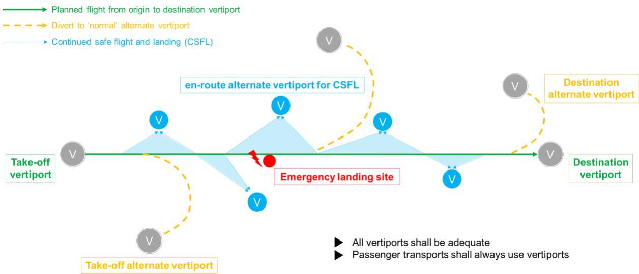
Figure F-1. En-route alternate vertiport for CSFL

# CHAPTER G — EMERGENCY PROCEDURES AND RFFS

# PTS VPT-DSN.G.1000 General

## Rationale

The establishment of emergency procedure and rescue and firefighting (RFF) services at heliports is provided in ICAO Annex 14, Volume II, Heliports and ICAO Document 9261, Heliport Manual, in accordance with a risk assessment, which is based on the construction of the heliport and helicopter, which is expected to be similar to VTOL-capable aircraft. However, VTOL-capable aircraft are powered by lithium-ion batteries, hydrogen fuel, or similar and the issue is whether the current RFF specifications for the heliports and aerodromes are adequate for the RFF solutions dealing with VTOL-capable aircraft fires. Currently, for heliports, this is geared towards fighting kerosene fires and would be rather ineffective at putting out battery fires. As VTOL-capable aircraft will mostly be powered by lithium-ion batteries, hydrogen or similar fuel, it would make sense that the current RFF recommendations are updated for vertiports and VTOL-capable aircraft.

## PTS VPT-DSN.G.1010 Hazard area

Note: Hazard area: some VTOL-capable aircraft, for example, those equipped with lithium-ion batteries, may not have the capability to extinguish an onboard fire and may thus need to land while venting the fire overboard. There may be other areas around the aircraft where a hazard to persons or equipment may exist; for example, due to moving surfaces or engine exhaust. These hazard areas are identified and depicted in the aircraft flight manual (AFM) (see example below) and should be considered when designing the vertiport; in particular the elements of Chapter C ‘Physical characteristics’, Chapter D ‘Obstacle environment’ and this Chapter G ‘Emergency procedures and RFFS’. Significant mean winds or other local characteristics may also warrant an extension of certain hazard areas.

![2c82cbdf4e7e2b58828b819bb78f9eea7c2f88d894df9afa520c0fcd4aabe719.jpg](https://aam-wiki.gksj.cc/uploads/images/gallery/2026-05/scaled-1680-/2c82cbdf4e7e2b58828b819bb78f9eea7c2f88d894df9afa520c0fcd4aabe719.jpg)  
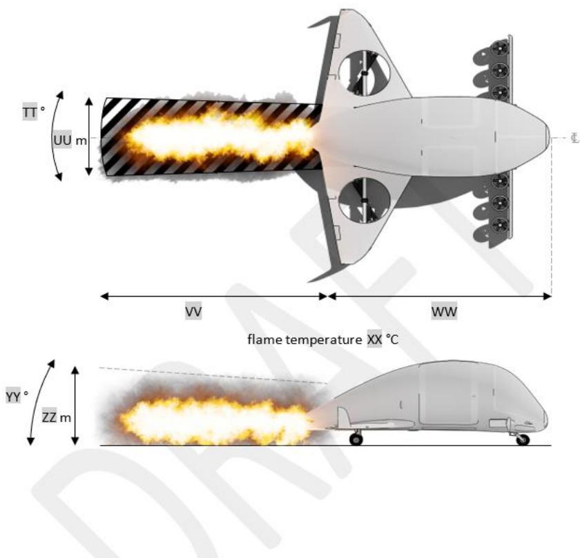
Figure G-1. Example of VTOL-capable aircraft hazard area

## Vertiport emergency response

## Disclaimer

As regards vertiport emergency response, EASA has not yet developed provisions. Below, for reference, the current ICAO material applicable for heliports and helicopters in its original version is provided. The ICAO material along with other available documents will be reviewed by EASA during the dedicated rulemaking task (RMT.0230 Drones) to ensure appropriate detailed provisions for vertiport emergency procedures.

## ICAO Annex 14, Volume II, Heliports, (5 edition, July 2020)

## CHAPTER 6. HELIPORT EMERGENCY RESPONSE

## 6.1 Heliport emergency planning

Introductory Note.— Heliport emergency planning is the process of preparing a heliport to cope with an emergency that takes place at the heliport or in its vicinity. Examples of emergencies include crashes on or off the heliport, medical emergencies, dangerous goods occurrences, fires and natural disasters. The purpose of heliport emergency planning is to minimize the impact of an emergency by saving lives and maintaining helicopter operations. The heliport emergency plan sets out the procedures for coordinating the response of heliport agencies or services (air traffic services unit, firefighting services, heliport administration, medical and ambulance services, aircraft operators, security services and police) and the response of agencies in the surrounding community (fire departments, police, medical and ambulance services, hospitals, military, and harbour patrol or coast guard) that could be of assistance in responding to the emergency.

6.1.1 A heliport emergency plan shall be established commensurate with the helicopter operations and other activities conducted at the heliport.

6.1.2 The plan shall identify agencies which could be of assistance in responding to an emergency at the heliport or in its vicinity.

6.1.3 Recommendation.— The heliport emergency plan should provide for the coordination of the actions to be taken in the event of an emergency occurring at a heliport or in its vicinity.

6.1.4 Recommendation.— Where an approach/departure path at a heliport is located over water, the plan should identify which agency is responsible for coordinating rescue in the event of a helicopter ditching and indicate how to contact that agency.

6.1.5 Recommendation.— The plan should include, as a minimum, the following information:

a) the types of emergencies planned for;

b) how to initiate the plan for each emergency specified;

c) the name of agencies on and off the heliport to contact for each type of emergency with telephone numbers or other contact information;

d) the role of each agency for each type of emergency;

e) a list of pertinent on-heliport services available with telephone numbers or other contact information;

f) copies of any written agreements with other agencies for mutual aid and the provision of emergency services; and

g) a grid map of the heliport and its immediate vicinity.

6.1.6 Recommendation.— All agencies identified in the plan should be consulted about their role in the plan.

6.1.7 Recommendation.— The plan should be reviewed and the information in it updated at least yearly or, if deemed necessary, after an actual emergency, so as to correct any deficiency found during an actual emergency.

6.1.8 Recommendation.— A test of the emergency plan should be carried out at least once every three years.

## ICAO Doc, 9261, Heliport Manual, Fifth edition, 2021

## HELIPORT EMERGENCY RESPONSE

## 6.1 HELIPORT EMERGENCY PLANNING

## 6.1.1 General

6.1.1 Heliport emergency planning is the process of preparing a heliport to cope with an emergency that takes place at the heliport or in its vicinity. This process minimizes the impact of an emergency by saving lives and restoring the heliport to normal operations as soon as practical.

6.1.2 Every heliport should establish an emergency plan commensurate with the complexity of helicopter operations and of other activities conducted at, or in the vicinity of, the heliport to deal with helicopter emergency situations.

6.1.3 The plan should include a set of instructions dealing with the arrangements designed to meet emergency conditions and steps that should be taken to see that the provisions of the instructions are periodically tested.

## 6.1.2 Plan contents

## 6.1.2.1 Type of emergencies

6.1.2.1.1 The heliport emergency plan should include possible emergencies to plan for and how to initiate the plan for each emergency.

## 6.1.2.1.2 Possible emergencies:

a) may involve aircraft:

1) accidents;

i) helicopter on-heliport; and

ii) helicopter off-heliport (in the vicinity):

– land; and

– water;

2) incidents;

i) helicopter on ground;

ii) sabotage including bomb threat; and

iii) unlawful seizure;

## b) not involving helicopter:

1) fire on the building and/or nearby buildings;

2) sabotage including bomb threat;

3) natural disaster;

4) dangerous goods occurrences; and

5) medical emergencies;

c) compound emergencies:

1) helicopter/structures;

2) helicopter/fuelling facilities;

3) helicopter/helicopter; and

4) helicopter/aeroplane

6.1.2.1.3 The aircraft emergencies for which services may be required are generally classified as:

a) local standby: when a helicopter approaching the heliport is known, or is suspected, to have developed some defect, but the problem is not such as would normally involve any serious difficulty in effecting a safe landing;

b) full emergency: when it is known that a helicopter approaching the heliport is, or is suspected to be, in such trouble that there is danger of an accident; and

c) helicopter accident: a helicopter accident which has occurred on or in the vicinity of the heliport.

## 6.1.2.2 Cooperating agencies

6.1.2.2.1 The heliport emergency plan should identify agencies that could assist or respond to an emergency at the heliport or in its vicinity. Names of agencies on and off the heliport, for each type of emergency, with telephone numbers or other contact information, should be included. The plan should also identify the role of each agency for each type of emergency, and a list of pertinent onheliport services available with telephone numbers or other contact information.

6.1.2.2.2 The heliport emergency plan should set out the procedures for coordinating the response of heliport agencies or services (air traffic services unit, firefighting services, heliport administration, medical and ambulance services, aircraft operators, security services and police) and the response of agencies in the surrounding community (fire departments, police, medical and ambulance services, hospitals, military and harbour patrol and/or coastguard agencies). Copies of any written agreements with other agencies for mutual aid and the provision of emergency services should be contained within the emergency plan.

## 6.1.2.3 Specified locations

6.1.2.3.1 The emergency organization should specify rendezvous point(s) and staging area(s) for the assisting services involved. A rendezvous point is a prearranged reference point, i.e. road junction, crossroads or other specified place, to which personnel or vehicles responding to an emergency situation initially proceed to receive directions to staging areas and/or the accident or incident site.

6.1.2.3.2 It is recommended that two grid maps (or equivalent) be provided: one map depicting the confines of heliport access roads, location of water supplies, rendezvous points, staging areas, railways, highways, difficult terrain, places with dangerous goods or harmful fluids, etc., and the other map of surrounding communities depicting appropriate medical facilities, access roads, rendezvous points, etc., within a distance of approximately 4 km from the heliport reference point. Where more than one grid map (or equivalent) is used, the scaling lines should not conflict and should be immediately identifiable to all participating agencies.

6.1.2.3.3 Copies of the map(s) should be kept at the emergency operations centre, the heliport operations office, heliport and local fire stations in the vicinity, all local hospitals, police stations, local telephone exchanges, and other similar emergency and information centres in the area.

## 6.1.2.4 Emergencies in difficult environments

6.1.2.4.1 The heliport emergency plan should include the availability of, and coordination with, appropriate specialist rescue services to respond to emergencies where a heliport is located close to water or swampy areas and/or where a significant portion of approach or departure operations takes place over these areas.

6.1.2.4.2 At those heliports located close to water, swampy areas or difficult terrain, the heliport emergency plan should include the establishment, testing and assessment at regular intervals of a predetermined response for the specialist rescue services.

## 6.1.2.5 Review and testing of the heliport emergency plan

6.1.2.5.1 The heliport emergency plan should be reviewed and its information updated at least yearly. After an actual emergency, a review of the heliport emergency plan should be conducted to identify any deficiencies arising as a result of the actual emergency.

6.1.2.5.2 The emergency plan should be regularly tested and should include the agencies identified in   
6.1.2.2.

## Rescue and firefighting services (RFFS)

## Disclaimer:

As regards vertiport emergency response, EASA has not yet developed provisions. Below, for reference, are provided the current ICAO material applicable for heliports and helicopters in its original version. The ICAO material along with other available documents will be reviewed by EASA during the dedicated rulemaking task (RMT.0230 Drones) to ensure appropriate detailed provisions for vertiport emergency procedures.

## ICAO Annex 14, Volume II, Heliports, (5th edition, July 2020)

## CHAPTER 6. HELIPORT EMERGENCY RESPONSE

## 6.2 Rescue and firefighting

Introductory Note.— It is important this section be read in conjunction with the appropriate detailed guidance on rescue and firefighting options given in the Heliport Manual (Doc 9261).

Provisions described in this section are intended to address incidents or accidents within the heliport response area only. No dedicated firefighting provisions are included for helicopter accidents or incidents that may occur outside the response area, such as on an adjacent roof near an elevated heliport.

Complementary agents are ideally dispensed from one or two extinguishers (although more extinguishers may be permitted where high volumes of an agent are specified, e.g. H3 operations). The discharge rate of complementary agents needs to be selected for optimum effectiveness of the agent used. When selecting dry chemical powders for use with foam, care needs to be exercised to ensure compatibility. Complementary agents need to comply with the appropriate specifications of the International Organization for Standardization (ISO).

Where a fixed monitor system (FMS) is installed, trained monitor operators, where provided, are positioned on at least the upwind location to ensure primary media is directed to the seat of the fire. For a ring-main system (RMS) practical testing has indicated that these solutions are only guaranteed to be fully effective for TLOFs up to 20 m diameter. If the TLOF is greater than 20 m, an RMS should not be considered unless supplemented by other means to distribute primary media (e.g. additional popup nozzles installed in the centre of the TLOF).

The International Convention for the Safety of Life at Sea (SOLAS) sets forth provisions on rescue and firefighting (RFF) arrangements for purpose-built and non-purpose-built shipboard heliports in SOLAS regulations II 2/18, II-2-Helicopter Facilities, and the SOLAS Fire Safety Systems Code.

It may therefore be assumed that this chapter does not include RFF arrangements for purpose built or non-purpose-built shipboard heliports or for winching areas.

## 6.2.1 Applicability

6.2.1.1 The following specifications shall apply to new builds or replacement of existing systems or part thereof from 1 January 2023: 6.2.2.1, 6.2.3.3, 6.2.3.4, 6.2.3.6, 6.2.3.7, 6.2.3.9, 6.2.3.10, 6.2.3.12, 6.2.3.13 and 6.2.4.2.

Note.— For areas for the exclusive use of helicopters at aerodromes primarily for the use of aeroplanes, distribution of extinguishing agents, response time, rescue equipment and personnel have not been considered in this section. See Annex 14, Volume I, Chapter 9.

6.2.1.2 Rescue and firefighting equipment and services shall be provided at helidecks and at elevated heliports located above occupied structures.

6.2.1.3 Recommendation.— A safety risk assessment should be performed to determine the need for RFF equipment and services at surface-level heliports and elevated heliports located above unoccupied structures.

Note.— Further guidance on factors to inform the safety risk assessment, including staffing models for heliports with only occasional movements and examples of unoccupied areas that may be located beneath elevated heliports, is given in the Heliport Manual (Doc 9261).

## 6.2.2 Level of protection provided

6.2.2.1 For the application of primary media, the discharge rate (in litres/minute) applied over the assumed practical critical area (in m2) shall be predicated on a requirement to bring any fire which may occur on the heliport under control within one minute, measured from activation of the system at the appropriate discharge rate.

## Practical critical area calculation where primary media is applied as a solid stream

Note.— This section is not applicable to helidecks regardless of how primary media is being delivered.

6.2.2.2 Recommendation.— The practical critical area should be calculated by multiplying the helicopter fuselage length (m) by the helicopter fuselage width (m) plus an additional width factor (W1) of 4 m. Categorization from H0 to H3 should be determined on the basis of the fuselage dimensions in Table 6-1.

Note 1.— For helicopters which exceed one or both of the dimensions for a category H3 heliport, it will be necessary to recalculate the level of protection using practical critical area assumptions based on the actual fuselage length and the actual fuselage width of the helicopter plus an additional width factor (W1) of 6 m.

Note 2.— The practical critical area may be considered on a helicopter type-specific basis by using the formula in 6.2.2.2. Guidance on practical critical area in relation to the heliport firefighting category is given in the Heliport Manual (Doc 9261) where a discretionary 10 per cent tolerance on fuselage dimension “upper limits” is applied.

Table 6-1. Heliport firefighting category
<table><tr><td>Category (d)</td><td>Maximum fuselage length (2)</td><td>Maximum fuselage width (3)</td></tr><tr><td>H0</td><td>up to but not including 8 m</td><td>1.5</td></tr><tr><td>H1</td><td>from 8 m up to but not including 12 m</td><td>2</td></tr><tr><td>H2</td><td>from 12 m up to but not including 16 m</td><td>2.5</td></tr><tr><td>H3</td><td>from 16 m up to 20 m</td><td>3</td></tr></table>

## Practical critical area calculation where primary media is applied in a dispersed pattern

6.2.2.3 Recommendation.— For heliports, except helidecks, the practical critical area should be based on an area contained within the heliport perimeter, which always includes the TLOF, and to the extent that it is load-bearing, the FATO.

6.2.2.4 Recommendation.— For helidecks, the practical critical area should be based on the largest circle capable of being accommodated within the TLOF perimeter.

Note.— Paragraph 6.2.2.4 is applied for the practical critical area calculation for helidecks regardless of how primary media is being delivered.

## 6.2.3 Extinguishing agents

Note 1.— Throughout section 6.2.3, the discharge rate of a performance level B foam is assumed to be based on an application rate of 5.5 L/min/m2, and for a performance level C foam and for water, is assumed to be based on an application rate of 3.75 L/min/m2. These rates may be reduced if, through practical testing, a State demonstrates that the objectives of 6.2.2.1 can be achieved for a specific foam use at a lower discharge rate (L/min).

Note 2.— Information on the required physical properties and fire extinguishing performance criteria needed for a foam to achieve an acceptable performance level B or C rating is given in the Airport Services Manual (Doc 9137), Part 1.

Surface level heliports with primary media applied as a solid stream using a portable foam application system (PFAS)

Note.— Except for a limited-sized surface-level heliport, the assumption is made that foam dispensing equipment will be transported to the incident or accident location on an appropriate vehicle (a PFAS).

6.2.3.1 Recommendation.— Where a rescue and firefighting service (RFFS) is provided at a surfacelevel heliport, the amount of primary media and complementary agents should be in accordance with Table 6 2.

Note.— The minimum discharge duration in Table 6-2 is assumed to be two minutes. However, if the availability of back-up specialist fire services is remote from the heliport, consideration may need to be given to increasing the discharge duration from two minutes to three minutes.

Table 6-2. Minimum usable amounts of  
extinguishing agents for surface-level heliports
<table><tr><td colspan="3">Foam meeting performance level B</td><td colspan="2">Foam meeting performance level C</td><td colspan="2">Complementary agents</td></tr><tr><td rowspan="2">Category (1)</td><td>Water (L)</td><td>Discharge rate foam solution/minute (L)</td><td>Water (L)</td><td>Discharge rate foam solution/minute (L)</td><td>Dry chemical powder (kg)</td><td>Gaseous media (kg)</td></tr><tr><td>(2) 500</td><td>(3) 250</td><td>(4) 330</td><td>(5) 165</td><td>(6) 23</td><td>(7) 9</td></tr><tr><td>HO H1</td><td>800</td><td>400</td><td>540</td><td>270</td><td>23</td><td>9</td></tr><tr><td>H2</td><td>1200</td><td>600</td><td>800</td><td>400</td><td>45</td><td>18</td></tr><tr><td></td><td>1600</td><td>800</td><td>1100</td><td>550</td><td>90</td><td>36</td></tr><tr><td>H3</td><td></td><td></td><td></td><td></td><td></td><td></td></tr></table>

Elevated heliports with primary media applied as a solid stream using a fixed foam application system (FFAS)

Note.— The assumption is made that primary media (foam) will be delivered through a fixed foam application system such as an FMS.

6.2.3.2 Recommendation.— Where an RFFS is provided at an elevated heliport, the amount of foam media and complementary agents should be in accordance with Table 6-3.

Note 1.— The minimum discharge duration in Table 6-3 is assumed to be five minutes.

Note 2.— For guidance on the provision of additional hand-controlled foam branches for the application of aspirated foam, see the Heliport Manual (Doc 9261).

Table 6-3. Minimum usable amounts of extinguishing agents for elevated heliports
<table><tr><td colspan="3">Foam meeting performance level B</td><td colspan="2">Foam meeting performance level C</td><td colspan="2">Complementary agents</td></tr><tr><td></td><td></td><td>Discharge rate foam solution/minute (L)</td><td>Water (L)</td><td>Discharge rate foam solution/minute (L)</td><td>Dry chemical powder (kg)</td><td>Gaseous media (kg)</td></tr><tr><td>Category (1)</td><td>Water (L) (2)</td><td>(3)</td><td>(4)</td><td>(5)</td><td>(6)</td><td>(7)</td></tr><tr><td>HO</td><td>1250</td><td>250</td><td>825 1350</td><td>165 270</td><td>23</td><td>9</td></tr><tr><td>H1</td><td>2000</td><td>400</td><td>2000</td><td>400</td><td>45 45</td><td>18</td></tr><tr><td>H2</td><td>3000</td><td>600</td><td></td><td></td><td></td><td>18</td></tr><tr><td>H3</td><td>4000</td><td>800</td><td>2750</td><td>550</td><td>90</td><td>36</td></tr></table>

Elevated heliports/limited-sized surface-level heliports with primary media applied in a dispersed pattern through an FFAS — a solid-plate heliport

6.2.3.3 Recommendation.— The amount of water required for foam production should be predicated on the practical critical area (m2) multiplied by the appropriate application rate (L/min/m2), giving a discharge rate for foam solution (in L/min). The discharge rate should be multiplied by the discharge duration to calculate the amount of water needed for foam production.

6.2.3.4 Recommendation.— The discharge duration should be at least three minutes.

6.2.3.5 Recommendation.— Complementary media should be in accordance with Table 6-3, for H2 operations.

Note.— For helicopters with a fuselage length greater than 16 m and/or a fuselage width greater than 2.5 m, complementary media in Table 6-3 for H3 operations may be considered.

Purpose-built elevated heliports/limited-sized surface-level heliports with primary media applied in a dispersed pattern through a fixed application system (FAS) — a passive fire retarding surface with water-only deck integrated firefighting system (DIFFS)

6.2.3.6 Recommendation.— The amount of water required should be predicated on the practical critical area (m2) multiplied by the appropriate application rate (3.75 L/min/m2) giving a discharge rate for water (in L/min). The discharge rate should be multiplied by the discharge duration to determine the total amount of water needed.

6.2.3.7 Recommendation.— The discharge duration should be at least two minutes.

6.2.3.8 Recommendation.— Complementary media should be in accordance with Table 6-3 for H2 operations.

Note.— For helicopters with a fuselage length greater than 16 m and/or a fuselage width greater than 2.5 m, complementary media for H3 operations may be considered.

Purpose-built helidecks with primary media applied in a solid stream or a dispersed pattern through a fixed foam application system (FFAS) — a solid-plate heliport

6.2.3.9 Recommendation.— The amount of water required for foam media production should be predicated on the practical critical area (m2) multiplied by the application rate (L/min/m2) giving a discharge rate for foam solution (in L/min). The discharge rate should be multiplied by the discharge duration to calculate the amount of water needed for foam production.

6.2.3.10 Recommendation.— The discharge duration should be at least five minutes.

6.2.3.11 Recommendation.— Complementary media should be in accordance with Table 6-3 to H0 levels for helidecks up to and including 16.0 m and to H1/H2 levels for helidecks greater than 16.0 m. Helidecks greater than 24 m should adopt H3 levels.

Note.— For guidance on the provision of additional hand-controlled foam branches for the application of aspirated foam, see the Heliport Manual (Doc 9261).

Purpose-built helidecks with primary media applied in a dispersed pattern through an FAS — a passive fire-retarding surface with water-only DIFFS

6.2.3.12 Recommendation.— The amount of water required should be predicated on the practical critical area (m2) multiplied by the application rate (3.75 L/min/m2) giving a discharge rate for water (in L/min). The discharge rate should be multiplied by the discharge duration to calculate the amount of water needed.

Note.— Sea-water may be used.

6.2.3.13 Recommendation.— The discharge duration should be at least three minutes.

6.2.3.14 Recommendation.— Complementary media should be in accordance with Table 6-3 to H0 levels for helidecks up to and including 16.0 m and to H1/H2 levels for helidecks greater than 16.0 m. Helidecks greater than 24 m should adopt H3 levels.

## 6.2.4 Response time

6.2.4.1 Recommendation.— At surface-level heliports, the operational objective of the RFF response should be to achieve response times not exceeding two minutes in optimum conditions of visibility and surface conditions.

Note.— Response time is considered to be the time between the initial call to the RFFS and the time when the first responding vehicle(s) (the service) is (are) in position to apply foam at a rate of at least 50 per cent of the discharge rate specified in Table 6-2.

6.2.4.2 Recommendation.— At elevated heliports, limited-sized surface-level heliports and helidecks, the response time for the discharge of primary media at the required application rate should be 15 seconds measured from system activation. If RFF personnel are needed, they should be immediately available on or in the vicinity of the heliport while helicopter movements are taking place.

## 6.2.5 Rescue arrangements

Recommendation.— Rescue arrangements commensurate with the overall risk of the helicopter operation should be provided at the heliport.

Note.— Guidance on rescue arrangements, e.g. options for rescue and for personal protective equipment to be provided at a heliport, is given in the Heliport Manual (Doc 9261).

## 6.2.6 Communication and alerting system

Recommendation.— A suitable alerting and/or communication system should be provided in accordance with the emergency response plan.

## 6.2.7 Personnel

Note.— The provision of RFF personnel may be determined by use of a task/resource analysis.   
Guidance is given in the Heliport Manual (Doc 9261).

6.2.7.1 Where provided, the number of RFF personnel shall be sufficient for the required task.

6.2.7.2 Where provided, RFF personnel shall be trained to perform their duties, and maintain their competence.

6.2.7.3 Rescue and firefighting personnel shall be provided with protective equipment.

## 6.2.8 Means of escape

6.2.8.1 Elevated heliports and helidecks shall be provided with a main access and at least one additional means of escape.

6.2.8.2 Recommendation.— Access points should be located as far apart from each other as is practicable.

Note.— The provision of an alternative means of escape is necessary for evacuation and for access by RFF personnel. The size of an emergency access/egress route may require consideration of the number of passengers and of special operations such as helicopter emergency medical services that require passengers to be carried on stretchers or trolleys.

## ICAO Doc, 9261, Heliport Manual, Fifth edition, 2021

## HELIPORT EMERGENCY RESPONSE

## 6.2 RESCUE AND FIREFIGHTING SERVICE (RFFS)

Note 1.— The specifications addressed in this section need not be applied to new builds, or replacement of existing systems, or part thereof, until 1 January 2023.

Note 2.— In the following text, the term ‘limited-sized heliport’ is used to describe a heliport where the firefighting capacity is concentrated at the FATO/TLOF and there is no requirement to move foam and/or water dispensing equipment.

## 6.2.1 Introduction

6.2.1.1 The principal objective of a rescue and firefighting response is to save lives. For this reason, the provision of a means of dealing with a helicopter accident or incident, occurring within the immediate vicinity (i.e. within the designated response area) of a heliport, assumes primary importance because it is within the response area that there are the greatest opportunities for saving lives by a dedicated heliport rescue and firefighting response. This will have to assume, at all times the possibility of, and need for, extinguishing a fire which may occur either immediately following a helicopter accident or incident, or at any time during a subsequent rescue phase.

6.2.1.2 The most important factors bearing on effective escape in a survivable helicopter accident are the speed of initiating a response and the effectiveness of that response. Where a heliport is located on top of a building that is occupied, it is also paramount, for the protection of inhabitants in the building beneath that any fire situation occurring at the heliport be rapidly brought under control. On a purpose-built heliport constructed of aluminium or steel, any effect the fire may have on the structural integrity of the helideck and/or its supporting structure has to be considered. In the event of a fire at a purpose-built heliport, a full structural analysis should be undertaken post-accident, and before helicopter operations are permitted to resume.

6.2.1.3 For a surface-level heliport, especially where it contains a remote FATO, a suitable vehicle may need to be provided to meet the response time objective stated in Annex 14, Volume II, Chapter 6. Where a heliport is located close to water, swampy areas or in difficult terrain and where a significant portion of the approach and departure operation takes place over these areas, an assessment will need to be carried out to determine if specialist RFFS equipment appropriate to specific hazards and risks should be made available. This may include, for example, a rescue boat.

6.2.1.4 Prior to selection of a dedicated heliport rescue and firefighting response (RFFR), the following should be considered: concept and definitions for the characteristics of helicopters; types of heliport facility they may be expected to operate to; and effective distribution of primary extinguishing agent to address a worst case crash and burn.

6.2.1.5 A heliport operator should also have a good understanding of emerging technologies that demonstrate effective methods for delivering primary extinguishing agents. To provide a speedy and effective response, a heliport operator should be able to determine the practical critical area, the response area and response time objectives for their facility.

## 6.2.2 Determining the required level of RFFS at a heliport

6.2.2.1 A risk assessment should be performed to first determine whether there is a need for rescue and firefighting equipment and services at surface level heliports and at elevated heliports located above unoccupied structures. This assessment should include staffing models for heliports without a dedicated RFFS and with only occasional movements, and for initiating the heliport emergency response.

6.2.2.4 The following factors need to be considered in any risk assessment, but it is the responsibility of the State of Operation to determine appropriate threshold limits, including:

a) number of movements planned/ unplanned;

b) frequency of movements;

c) total number of helicopters in use at the site during peak periods;

d) type of movements, i.e. whether conducting commercial air transport (CAT) and/or general aviation (GA);

## e) number of passengers;

f) types of helicopters in use, their certification status with respect to crashworthiness (see Appendix B to Chapter 6) and their performance characteristics;

g) size and complexity of the response area, e.g. other helicopters are present in apron area;

h) nature of the terrain, e.g. located near water or swampy areas;

i) whether the heliport is elevated or at surface level;

j) whether the heliport is in a congested or non-congested environment;

k) availability of the local fire and rescue services, i.e. how rapidly can services respond to an incident on the heliport;

l) types of helicopters and specific hazards, e.g. construction materials are used in airframes such as composites, i.e. man-made mineral fibres (MMMF); and

m) whether or not an emergency response plan has been established.

## 6.2.3 Heliport staffing levels

6.2.3.1 The degree of complexity of the heliport and the emergency planning arrangements in place will help to inform heliport staff to execute the heliport emergency plan effectively. The number of personnel used and their given training, are decisions for heliport management and should be fully documented. In order to establish staffing levels, a task/resource analysis should be carried out.

6.2.3.2 The heliport emergency plan exists to identify agencies that could be of assistance in responding to an emergency at the heliport, or in its vicinity. This could include, but may not be limited to, a helicopter crash, whether or not resulting in a post-crash fire, or a medical emergency or a dangerous goods occurrence. If, due in particular to a low number of movements, a dedicated RFFS is not provided, whether at a surface level heliport or elevated heliport located above an unoccupied structure, there should be a specified method for invoking the heliport emergency plan.

6.2.3.3 Where present, designated personnel should invoke the heliport emergency plan. If the heliport is unattended, the heliport emergency plan should be activated remotely.

## 6.2.4 Level and method of protection

## 6.2.4.1 Helicopter characteristics and parameters to be considered

6.2.4.1.1 For the defined areas of a heliport, overall length and maximum take-off mass of the design helicopter are the critical parameters for a designer. For a dedicated firefighting service (FFS) at a heliport, the critical parameters are fuselage length and fuselage width. These dimensions are usually available in the helicopter’s Type Certificate and in the helicopter flight manual.

6.2.4.1.2 The fuselage consists of the central portion of the helicopter designed to accommodate the aircrew and the passengers and/or cargo. Fuselage length is often presented (conservatively) in flight manuals as the distance between the nose of the helicopter and the end of the tail boom, and fuselage width as the overall width of the occupied portion of the helicopter excluding the undercarriage.

## 6.2.4.2 Practical critical area

6.2.4.2.1 To determine the amount of water required for foam production it is first necessary to calculate a practical critical area (in m2) which is multiplied by the application rate (in L/min/m2) of the respective foam performance level to determine the discharge rate for foam solution (in L/min). By multiplying the discharge rate by the discharge duration, this determines the amount of water needed for foam production.

6.2.4.2.2 The assumptions used to determine practical critical area (helicopters) depend on whether primary extinguishing agent (usually foam) is initially applied in a solid stream (jet) application or in a dispersed (spray) pattern.

6.2.4.2.3 A solid stream is used for firefighting when range of application is essential. In this case the practical critical area is limited to the fuselage dimensions of the helicopter plus an additional width factor. Delivering foam solution for initial attack from a fixed monitor system (FMS) located on the periphery of the heliport, or from a hose-line, in a jet configuration, are examples of typical solid stream applications. In each case, once the fire has been brought under control during the initial attack, there is usually a facility to adjust the nozzle, changing the throughput of equipment from a solid stream application to a dispersed pattern, i.e. the nozzle is adjusted from a jet to a spray (fog) pattern. Where applicable, this provides a safer environment for rescue crews to approach the accident/ incident location.

6.2.4.2.4 The practical critical area (helicopters), where primary extinguishing agent is applied as a solid stream-jet, is determined by multiplying the maximum fuselage length for a given firefighting category (H0 to H3) by the maximum fuselage width of the same category, then applying an additional width factor (W1) of 4 m. Alternatively, by knowing the fuselage length and width dimensions, a practical critical area calculation can be applied to any specific type of helicopter; this has an application, in practice, when only one type of helicopter is being operated at a heliport.

6.2.4.2.5 A dispersed pattern is used at heliports when it is necessary to deliver foam and/or water at shorter ranges, combining greater coverage with a more effective surface application of the primary extinguishing agent. Here, due to the greater coverage of primary extinguishing agent applied in a dispersed spray pattern, the assumed practical critical area has to be much larger than in a case where primary extinguishing agent is applied in a solid stream (jet). A particularly effective way of delivering primary extinguishing agent in a dispersed pattern is through a Deck Integrated Fire Fighting System (DIFFS) typically consisting of a series of flush-mounted nozzles positioned over the surface of the practical critical area which, upon activation, are capable of delivering primary extinguishing agent to the entire loadbearing area of the heliport.

6.2.4.2.6 The practical critical area (helicopters) where primary extinguishing agent is applied in a dispersed (spray) pattern, is predicated on the dimensions of the operating area that needs to be protected. For an onshore purpose built, or limited-sized heliport (e.g. an elevated heliport at rooftop level), the practical critical area is assumed to accommodate the whole load-bearing area which always includes the TLOF, and to the extent that it is a load-bearing surface, the FATO also. In this case, the area to be considered is based on the specific shape of the TLOF, and where applicable, the shape of the FATO.

6.2.4.2.7 Another form of foam dispensing equipment, capable of delivering primary extinguishing agent in a dispersed pattern, is a ring-main system (RMS). In this case, equally spaced nozzles are located around the perimeter of the practical critical area, just above the surface, capable of directing extinguishing agent from the perimeter towards the centre of the landing area. Given the relative ranges at which nozzles are expected to perform, especially in windy conditions, it has been established through practical testing that sole use of an RMS has proven ineffective for TLOFs which are greater than 20 m diameter. In this case, an RMS could only be utilised effectively if supplemented by DIFF nozzles in the centre of the TLOF (a combination solution of RMS plus DIFFS). However, in the case of a large new-build heliport, it is probably more cost-effective and efficient, to provide a full DIFFS.

## 6.2.4.3 Fixed foam application systems (FFAS)

6.2.4.3.1 When installed at a heliport, a fixed foam application system (FFAS) should deliver a primary foam extinguishing agent at the required application rate and over the assumed practical critical area. An FFAS may include, but not necessarily be limited to, an FMS), a DIFFS or a RMS. A variation on an FFAS is a fixed application system (FAS) capable of applying water-only in a dispersed pattern. An FAS is only permitted when it is used in tandem with a passive fire-retarding surface.

Note 1.— Where an FMS is installed, trained monitor operators, where provided, should be positioned on at-least the upwind location to ensure the primary extinguishing agent is directed efficiently to the seat of the fire.

Note 2.— Compressed air foam systems (CAFS) may be considered, with foam distributed through a DIFFS using Performance Level B foam (BCAFS). Fire suppression capabilities are enhanced by injecting compressed air into the foam to generate an effective solution to control a fire on the heliport. This type of foam has a tighter, denser bubble structure than standard foams, which allows it to penetrate deeper into the fire before the bubbles are broken down. BCAFS rapidly controls a fire by smothering it (starving it of oxygen), by diminishing heat, using trapped air within the bubble structure, and by disrupting the chemical reaction needed for a fire to continue. Consequently, the opportunity presents to deliver BCAFS at a lower application rate than would otherwise be required for a Standard Level B foam.

6.2.4.3.2 An FFAS may be used at a limited-sized heliport where there is no requirement to physically move foam dispensing equipment towards the fire (hence the equipment is fixed in location). Where foam dispensing equipment is required to be moved towards the accident/ incident location, this is classed as a portable foam application system (PFAS).

## 6.2.4.4 Additional hand-controlled foam branches for the application of aspirated foam

6.2.4.4.1 Not all fires are capable of being accessed by fixed foam application systems (FFAS) delivering foam as a solid stream. Further, in certain scenarios, their use may endanger helicopter occupants who are seeking to escape from the fire. Therefore, in addition to solid stream FFAS, there should be the ability to deploy at least two deliveries with handcontrolled foam branch pipes for the application of aspirated foam at a minimum rate of 225-250 litres/minute through each hose line.

6.2.4.4.2 A single hose line, capable of delivering aspirated foam at a minimum application rate of 225- 250 litres/minute, may be acceptable where the hose line is a sufficient length, and the hydrant system of sufficient operating pressure for the effective distribution of foam to any part of the practical critical area, regardless of wind strength or direction.

6.2.4.4.3 Taking account of the open-air environment in which equipment is expected to perform, a low expansion foam should be used. An inline foam inductor is provided to induct the foam concentrate into the water stream to supply a proportioned solution of concentrate and water to foam producing equipment. The inline inductor should be set to the appropriate rate corresponding to the strength of the foam concentrate used e.g. 3 per cent or 6 per cent.

6.2.4.4.4 The hose line(s) provided should be capable of being fitted with a branch pipe able to apply water in the form of a jet or spray pattern for cooling, or for specific firefighting tactics.

## 6.2.4.5 Portable foam application systems (PFAS)

6.2.4.5.1 For some heliports, it becomes necessary to move primary extinguishing agent-dispensing equipment towards the accident or incident location, for example at a surface level heliport operating a remote FATO (analogous to a fixed wing runway operation at an airport, where the fire vehicle has to be positioned from a location remote to the runway).

6.2.4.5.2 The ability to transport the equipment to the accident location means it is classed as a PFAS which, having been moved to the fire location is then capable of distributing primary extinguishing agent at the required application rate over the assumed practical critical area. A PFAS may include, but not necessarily be limited to, hand-controlled portable foam branch pipes capable of being pulled across the heliport surface by trained personnel (see 6.2.4.4), and monitors or foam cannons that are mounted on an appropriate rescue and firefighting vehicle and then transported to the scene of an accident as part of the rescue and firefighting response for the heliport.

## 6.2.4.6 Solid plate heliports and passive fire-retarding surfaces

6.2.4.6.1 Most new-build purpose-built heliports are either constructed of aluminium or steel with aluminium or steel support structures. A solid plate surface is set to an appropriate fall or camber (typically 1:100) which allows burning fuel to drain across the solid surface of the heliport into a suitable drainage collection system, whether the fall or camber emanates from the centre of the TLOF or at the perimeter edge.

6.2.4.6.2 As an alternative to the solid-plate surface, many manufacturers now give an option to install a passive fireretarding surface which, at a purpose-built heliport is constructed in the form of a perforated surface or grating, containing numerous holes that allow burning fuel to rapidly drain through the surface of the heliport, in some cases to an intermediate safety screen and that functions to extinguish the fire (by starving it of oxygen) permitting, now un-ignited, fuel to drain away to a safe collection area. Other systems have no safety screen inside the deck chambers but function by removing the heat from a fire via novel hole sizes and patterns.

6.2.4.6.3 The good thermal conductivity of aluminium, coupled with the fuel flow profile, facilitates a rapid cooling effect on the burning fuel, extinguishing any fire that flows into the decking. These systems, when used in combination with a water-only DIFFS, have been demonstrated to show that any residual fire burning over the surface of the heliport remains insignificant given that the fuel source is constantly draining away to a safe area.

6.2.4.6.4 Where a passive fire-retarding surface is selected in lieu of a solid plate surface, the requirement to provide foam for primary extinguishing agent is removed since most of the fuel is directed immediately away from the surface restricting the intensity of the subsequent fire and what residual fire does remain above the surface is insignificant and can be extinguished with the use of water.

6.2.4.6.5 One of the issues with most passive systems is the year-round tendency to collect debris or contaminants which could result in a reduction of efficacy. The heliport maintenance program should include the regular inspection and clearing of such debris and contaminants.

## 6.2.4.7 Complementary agents

6.2.4.7.1 Complementary agents should ideally be dispensed from one or two extinguishers, although more containers may be permitted when high volumes of the agent are specified, e.g. for H3 operations.

6.2.4.7.2 The discharge rate of complementary agents should be selected for the optimum effectiveness of the agent used. When selecting dry chemical powder for use with foam, compatibility should be ensured. Complimentary agents should comply with the appropriate specifications of the International Organization for Standardization (ISO).

## 6.2.4.8 Fire control time

6.2.4.8.1 A fire is deemed to be under control at the point when the initial intensity of the fire is reduced by 90 per cent. The helicopter operation, consistent also with a fixed wing operation, should achieve a 1-minute control time in the practical critical area using a quantity of primary extinguishing agent for initial attack, over an appropriate discharge duration, which is required for the continued control of the fire thereafter, and/or for possible complete extinguishment of the fire and which may have spread across the heliport operating area.

6.2.4.8.2 Speed of response has an important bearing on the effectiveness of escape in a survivable helicopter accident. Intuitively, a prompt intervention will likely bring the fire under control more quickly if firefighting p

## 6.2.4.9 Summary of potential solutions

Table II-6-2 contains a summary of the firefighting solutions presented in Annex 14, Volume II, Chapter 6; a quick guide/key summary is provided in Table II-6-3.

Table II-6-2. Summary of firefighting options presented in Annex 14, Volume II
<table><tr><td rowspan=1 colspan=1>Heliport type</td><td rowspan=1 colspan=1>Application method</td><td rowspan=1 colspan=1>Criticalarea assumptions</td><td rowspan=1 colspan=1>Dischargeduration</td><td rowspan=1 colspan=1>Primaryextinguishingagent</td><td rowspan=1 colspan=1>Responsetime objective</td></tr><tr><td rowspan=1 colspan=1>Surface level</td><td rowspan=1 colspan=1>Solid streamPFAS</td><td rowspan=1 colspan=1>FuselagedimensionsHO-H3</td><td rowspan=1 colspan=1>2 minutes</td><td rowspan=1 colspan=1>Level B/C foam</td><td rowspan=1 colspan=1>2 minutes</td></tr><tr><td rowspan=1 colspan=1>Elevated</td><td rowspan=1 colspan=1>Solid streamFFAS/solid plate</td><td rowspan=1 colspan=1>FuselagedimensionsHO-H3</td><td rowspan=1 colspan=1>5 minutes</td><td rowspan=1 colspan=1>Level B/C foam</td><td rowspan=1 colspan=1>15 seconds</td></tr><tr><td rowspan=1 colspan=1>Elevated/surface level</td><td rowspan=1 colspan=1>Dispersed patternsolid plate</td><td rowspan=1 colspan=1>TLOF +load-bearingFATO</td><td rowspan=1 colspan=1>3 minutes</td><td rowspan=1 colspan=1>Level B/C foam</td><td rowspan=1 colspan=1>15 seconds</td></tr><tr><td rowspan=1 colspan=1>Elevated/surface level</td><td rowspan=1 colspan=1>Dispersed patternpassive surface</td><td rowspan=1 colspan=1>TLOF +load-bearingFATO</td><td rowspan=1 colspan=1>2 minutes</td><td rowspan=1 colspan=1>Water-only</td><td rowspan=1 colspan=1>15 seconds</td></tr></table>

Table II-6-3. Quick guide/key
<table><tr><td rowspan=2 colspan=2>PFAS</td><td rowspan=3 colspan=1>Portable foam application system, e.g. hose-line, foam cannon on a rescuevehicle.</td></tr><tr><td rowspan=2 colspan=1>FFAS</td></tr><tr><td></td><td rowspan=2 colspan=1>Fixed foam application system, e.g. FMS, DIFFS, RMS.</td></tr><tr><td rowspan=2 colspan=1></td><td></td></tr><tr><td></td><td rowspan=2 colspan=1></td></tr><tr><td rowspan=2 colspan=1>Solid stream application</td><td></td></tr><tr><td></td><td rowspan=2 colspan=1>Foam delivered to a concentrated area in the form of a jet, e.g. foam monitors.</td></tr><tr><td rowspan=2 colspan=1>Dispersed pattern application</td><td></td></tr><tr><td></td><td rowspan=2 colspan=1>Foam delivered over a wider area from nozzles mounted in the deck surface,e.g. DIFFS.</td></tr><tr><td rowspan=2 colspan=1>Solid plate surface</td><td></td></tr><tr><td rowspan=2 colspan=2>Impervious to liquids.</td></tr><tr><td rowspan=2 colspan=1> Passive fire-retarding surface</td></tr><tr><td rowspan=2 colspan=2> Incorporates numerous drain holes to allow fuel (and other liquids) to drainthrough the surface.</td></tr><tr><td rowspan=2 colspan=1>Fire control time</td></tr><tr><td rowspan=1 colspan=2>The assumed fire control time in all cases is 1 minute from discharge ofprimary media at full application rate.</td></tr><tr><td rowspan=1 colspan=3>The application rate for a Performance Level B foam is 5.5 L/min/m².</td></tr></table>

The application rate for a Performance Level C foam and for water, is 3.75 L/min/m².

## 6.2.5 Meeting the response time objective

6.2.5.1 The most important factors bearing on effective escape in a survivable helicopter accident at a heliport are the speed of initiating a response and the effectiveness of that response. The response time for heliports can be defined as the period that lapses between the occurrence of the incident or accident and the first application of primary extinguishing agent to the fire, except for a surface-level heliport where primary extinguishing agent is applied as a solid stream from an appropriately equipped rescue and firefighting vehicle. In this case, response time is measured from the initial call to the RFFS to the time when the first responding vehicles are in place to apply foam at a rate of at least 50 per cent of the required discharge rate.

6.2.5.2 For an FFAS located at an elevated heliport, the initial response should be comparatively quick because primary extinguishing agent-dispensing equipment will already be located adjacent to the scene of the incident (or accident) and 100 per cent discharge capability can be achieved in a relatively short space of time (up to 15 seconds after activation of the system). However, where it is necessary to move primary extinguishing agent-dispensing equipment to the scene of the incident or accident (i.e. a PFAS located on a vehicle), the response time is likely to be more protracted (up to 2 minutes in optimum conditions of visibility and surface conditions).

6.2.5.3 Applying a common timeline to a similar scale incident or accident, which occurs either on a confined-area heliport, using a FFAS, or at a remote surface level FATO, where intervention is via an appropriately equipped rescue vehicle (PFAS), it is reasonable to assume that the fire situation occurring in the first case will be brought under control, or even extinguished, before a PFAS is even on-scene at a remote FATO on a surface-level heliport (where a 2 minute response time objective in optimum conditions is permitted). This means that the confined-area heliport is very favourably positioned when considering the most important factors bearing on effective escape in a survivable helicopter accident: the speed of initiating the response and the effectiveness of that response.

6.2.5.4 In considering the response area at a heliport, all areas used for the manoeuvring, landing, take-off, rejected take-off, ground taxiing, air-taxiing and parking of helicopters that are in the direct control of the heliport operator should be considered. At a limited-sized heliport, including surface level, the response area will usually be the TLOF, and when load bearing, the FATO. However, if a heliport is served by one or more taxiways linking to stands, the heliport operator will have to consider rescue and firefighting arrangements for each additional element of the response area that is under their control.

6.2.5.5 At a surface-level heliport laid out in a similar way to a fixed wing airport, with a remote FATO serviced by a taxiway system linking to an apron with one or more stands, the rescue and firefighting response will normally be provided by a PFAS, i.e. a specialist vehicle, and in this case, following an alarm, firefighting and rescue equipment will be moved directly to the scene of the incident or accident.

## 6.2.6 Rescue arrangements

Rescue arrangements may include, but are not limited to, an assisted-rescue or self-rescue model predicated on the results of a risk assessment. Where a self-rescue model is promoted, it is especially important to establish the respective roles and interfaces between agencies on and off the heliport. This should form part of the heliport emergency plan and be periodically tested.

## 6.2.7 Communication and alerting system

6.2.7.1 A discrete communication system should be provided linking the rescue and firefighting service with central control and RFF vehicles (when provided). The mobilization of all parties and agencies required to respond to an aircraft emergency on a large heliport will require the provision and management of a complex communications system. The requirement is examined in the Airport Services Manual, Part 7 – Airport Emergency Planning, Chapter 12 (Doc 9137).

6.2.7.2 An alerting system for RFF personnel should be provided at their base facility and be capable of being operated from that location, at any other areas where RFF personnel congregate, and in the control tower (when provided). Examples include:

a) direct telephone line to the rescue control center or service room of the rescue personnel;

b) alarm button for direct alarm of the fire brigade;

c) heat sensor for alarm and/or automatic switching of the extinguishing system; or

d) monitored video surveillance.

6.2.7.3 Further detailed guidance on communication and alarm requirements is detailed in the Airport Services Manual, Part 1 – Rescue and Fire Fighting, Chapter 4 (Doc 9137).

## 6.2.8 RFFS personnel

The provision of rescue and firefighting personnel should be determined using a task and resource analysis. Depending on the rescue model employed (whether an assisted or self-rescue model), sufficient dedicated heliport rescue and firefighting personnel should be provided with appropriate training and with personal protective equipment (PPE) to enable them to perform their duties effectively.

## 6.2.8.2 Rescue equipment

6.2.8.2.1 Guidance on minimum equipment inventory required to ensure effective rescue arrangements are in place at the heliport are listed in Table II-6-4.

6.2.8.2.2 Equipment should only be used by personnel who have received adequate information, instruction and training.

## Table II-6-4. Rescue equipment

Adjustable wrench 1

Rescue axe, large (non-wedge or aircraft type) 1

Cutters, bolt 1

Crowbar, large 1

Hook, grab or salving 1

Hacksaw (heavy duty) and six spare blades 1

Blanket, fire resistant 1

Ladder (two-piece) \* 1

Lifeline (5 mm circumference x 15 m in length) plus rescue harness 1

Pliers, side cutting (tin snips) 1

Set of assorted screwdrivers 1

Harness knife and sheath or harness cutters \*\*

Man-Made Mineral Fibre (MMMF) Filter masks \*\*

Gloves, fire resistant \*\*

Power cutting tool\*\*\* 1

\* For access to casualties in an aircraft that may be on its side, the ladder should be of an appropriate length.

\*\* This equipment is required for each heliport crew member.

\*\*\* Requires additional approved training by competent personnel. Equipment only specified for helicopters with a D-value above 24m.

## 6.2.8.3 Personal protective equipment (PPE)

6.2.8.3.1 Depending on the rescue model employed (whether an assisted or self-rescue model), sufficient dedicated heliport rescue and firefighting personnel should be provided with appropriate training and with PPE to enable them to perform their duties effectively.

6.2.8.3.2 Specific outcomes from a task-resource analysis would determine whether there is a requirement for RFF personnel to be provided with PPE, or whether given the specific rescue model in use (e.g. self-rescue, fixed automatic system), PPE is not required.

6.2.8.3.3 All responding RFF personnel should be provided with appropriate PPE and respiratory protective equipment (RPE) to allow them to carry out their duties in an effective manner.

6.2.8.3.4 Personnel qualified to operate the RFF equipment effectively should be dressed in protective clothing prior to helicopter movements taking place. In addition, equipment should only be used by personnel who have received adequate information, instruction and training. PPE should be accompanied by suitable safety measures, e.g. protective devices, markings and warnings. The specifications for PPE should meet one of the international standards shown in Table II-6-5.

Table Il-6-5. Standards for PPE
<table><tr><td rowspan=1 colspan=1>Item</td><td rowspan=1 colspan=1>NFPA</td><td rowspan=1 colspan=1>EN</td><td rowspan=1 colspan=1>BS</td></tr><tr><td rowspan=1 colspan=1>Helmet with visor</td><td rowspan=1 colspan=1>NFPA 1971</td><td rowspan=1 colspan=1>EN443</td><td rowspan=1 colspan=1>BS EN 443</td></tr><tr><td rowspan=1 colspan=1>Gloves</td><td rowspan=1 colspan=1>NFPA 1971</td><td rowspan=1 colspan=1>EN659</td><td rowspan=1 colspan=1>BS EN 659</td></tr><tr><td rowspan=1 colspan=1>Boots (footwear)</td><td rowspan=1 colspan=1>NFPA 1971</td><td rowspan=1 colspan=1>ENISO 20345</td><td rowspan=1 colspan=1>EN ISO 20345</td></tr><tr><td rowspan=1 colspan=1>Tunic and trousers</td><td rowspan=1 colspan=1>NFPA 1971</td><td rowspan=1 colspan=1>EN469</td><td rowspan=1 colspan=1>BS EN ISO 14116</td></tr><tr><td rowspan=1 colspan=1>Flash-hood</td><td rowspan=1 colspan=1>NFPA 1971</td><td rowspan=1 colspan=1>EN 13911</td><td rowspan=1 colspan=1>BS EN 13911</td></tr></table>

6.2.8.3.5 Appropriate personnel should be appointed to ensure that all PPE is installed, stored, used, checked and maintained in accordance with the manufacturer’s instructions. Facilities should be provided for the cleaning, drying and storage of PPE when crews are off duty. Facilities should be wellventilated and secure.

## 6.2.9 Means of escape

A minimum of two access/egress points should be provided to give occupants of a helicopter the option to escape upwind of a helicopter fire. The provision of an alternative means of escape is necessary for evacuation and for access by rescue and firefighting personnel. The size of an emergency

access/egress route may require consideration of the number of passengers and of special operations like helicopter emergency medical services (HEMS) that require passengers to be carried on stretchers or trolleys.

# APPENDIX 1 — REFERENCE VALUE FOR VTOL-CAPABLE AIRCRAFT OBSTACLE PROTECTION

For helicopter obstacle protection, the largest overall dimension of the aircraft is used when designing heliports. A key parameter for obstacle protection is however the diameter of the smallest enclosing circle as, by definition, it is the smallest circle in which the aircraft can fit, without hitting obstacles located outside the circle. This appendix will examine the relationship between these two parameters to determine which one is appropriate for VTOL obstacle protection.

## Notations:

d = largest overall dimension

D = diameter of the smallest enclosing circle

x = longitudinal axis

y = lateral axis (+ left)

## Assumptions:

\- the aircraft is symmetrical in y

\- the projection on a horizontal plane is considered

## Case 1: smallest enclosing circle defined by 2 points

For some aircraft, it can be that the smallest enclosing circle is defined by 2 points (A and B on Figure 1). This is the case for helicopters where one point is the forward tip of the main rotor disk and the other one is the aft tip of the tail rotor disk or tail cone or tail rotor guard.

![b6c9b4321d0f66567071ff5ee9eea64a8cc490b7f003d109e732286a132d5ffe.jpg](https://aam-wiki.gksj.cc/uploads/images/gallery/2026-05/scaled-1680-/b6c9b4321d0f66567071ff5ee9eea64a8cc490b7f003d109e732286a132d5ffe.jpg)  
Figure 1. Smallest enclosing circle defined by 2 points (A and B)

In such case, the largest overall dimension is AB as well, thus:

![6a3f71f978ff168c5ea937da3632ac467903a8145e7030c00d99181ddda3c7e9.jpg](https://aam-wiki.gksj.cc/uploads/images/gallery/2026-05/scaled-1680-/6a3f71f978ff168c5ea937da3632ac467903a8145e7030c00d99181ddda3c7e9.jpg)

For helicopters, it does therefore not matter if referring to the largest overall dimension or the diameter of the smallest circle for obstacle protection, as they are equal. It is thus proposed to keep the existing definition for helicopters.

## Case 2: smallest enclosing circle defined by 3 points

For some VTOL aircraft, the smallest enclosing circle may be defined by 3 points. An example is presented on Figure 2 with the 3 points A, B and B’.

![15b1ea62e54a8f281fb513e40e43c4d0b56d1321ecf104b6875d7e4c543e7a1d.jpg](https://aam-wiki.gksj.cc/uploads/images/gallery/2026-05/scaled-1680-/15b1ea62e54a8f281fb513e40e43c4d0b56d1321ecf104b6875d7e4c543e7a1d.jpg)  
Figure 2. Smallest enclosing circle defined by 3 points (A, B and B’).

We will consider a case where A is on the longitudinal axis, with the dimensions normalized on y so that the coordinates of the defining points are A (x,0), B (1,0) and B’ (-1,0) as can be seen on Figure 3.

The largest overall dimension is assumed to be located within ABB’ (all points are within the dark blue arcs on Figure 2).

## Determining d:

Let x0 be the value of x below which the largest overall dimension is BB’. ABB’ then define an equilateral triangle and we have:

$$
\mathsf { B B ^ { \prime } } \mathsf { \bar { \Psi } } \mathrm { = } \mathsf { A B ^ { 2 } } \mathsf { = } \mathsf { X 0 } ^ { 2 } \mathsf { + } \mathsf { Y B } ^ { 2 }
$$

$$
2 ^ { 2 } = x _ { 0 } { } ^ { 2 } + 1 ^ { 2 }
$$

$$
\times \infty = \sqrt { 3 }
$$

If x ≤ x0 then AB ≤ BB’ thus d=2

• If x > x0 then d=AB

$$
{ \mathsf { d } } ^ { 2 } { \mathsf { = } } { \mathsf { x } } ^ { 2 } { \mathsf { + } } 1 ^ { 2 }
$$

$$
{ \mathsf { d } } { = } \sqrt { \mathbf { X } ^ { 2 } + 1 }
$$

![c2221a105813d7802197b4f5b8ff573f12808d08ce6ded35b9fc54bf1f639933.jpg](https://aam-wiki.gksj.cc/uploads/images/gallery/2026-05/scaled-1680-/c2221a105813d7802197b4f5b8ff573f12808d08ce6ded35b9fc54bf1f639933.jpg)  
Figure 3. Coordinates of A, B and B’ and largest overall dimension limit value x0.

Determining D:

If x ≤ 1 then D=2, this is equivalent to case 1

• If x > 1 then

Let R=D/2 and C be the center of the smallest enclosing circle

As can be seen on Figure 4, we have

R2=xC2+ yB2

and

![40699a0aee40aebf58a640d8ae304acc6a53c0467837eb316e02f7ded21dcf6b.jpg](https://aam-wiki.gksj.cc/uploads/images/gallery/2026-05/scaled-1680-/40699a0aee40aebf58a640d8ae304acc6a53c0467837eb316e02f7ded21dcf6b.jpg)  
Figure 4. Center and radius of the smallest enclosing circle.

thus

$$
R ^ { 2 } = ( x - R ) ^ { 2 } + y _ { B } ^ { 2 }
$$

$$
\scriptstyle \mathsf { R } = \frac { 1 } { 2 } \left( x + \frac { y _ { B } ^ { 2 } } { x } \right)
$$

$$
\mathsf { D } \boldsymbol { = } \boldsymbol { x } + \frac { \boldsymbol { 1 } } { \boldsymbol { x } }
$$

Thus, for x ≤ x0

$$
\begin{array} { r } { \frac { D } { d } = \frac { 1 } { 2 } \Big ( x + \frac { 1 } { x } \Big ) } \end{array}
$$

and for x > x0

$$
{ \frac { D } { d } } = { \frac { x + { \frac { 1 } { x } } } { \sqrt { x ^ { 2 } + 1 } } }
$$

$$
\boxed { \begin{array} { l } { \boxed { D } = \frac { \sqrt { x ^ { 2 } + 1 } } { x } } } \end{array}
$$

D/d is plotted as a function of x on Figure 5.

![4548f4e27e779a3f630d3c4229896f757004cc5e616fb4bbec65281e7493ae6b.jpg](https://aam-wiki.gksj.cc/uploads/images/gallery/2026-05/scaled-1680-/4548f4e27e779a3f630d3c4229896f757004cc5e616fb4bbec65281e7493ae6b.jpg)  
Figure 5. Ratio of the diameter of the smallest enclosing circle to the largest overall dimension as a function of x.

(D/d)(x) is monotonically increasing before x0 and decreasing after, thus the maximum for D/d is reached for $\mathsf { x } = \mathsf { x } _ { 0 } = \sqrt { 3 }$ , and we obtain:

$$
\left( { \frac { D } { d } } \right) _ { m a x } = { \frac { 2 } { \sqrt { 3 } } }
$$

## Case 3: smallest enclosing circle defined by 4 points

In this case we are considering an aircraft geometry where the smallest enclosing circle is defined by 4 points A, A’, B and $\mathsf { B } ^ { \prime }$ as depicted on Figure 6. The dimensions are normalized on y, so that the coordinates of the defining points are A (x,y), A’ (x,-y), B (1,0), B’ (-1,0)

The largest overall dimension is assumed to be located within AA’B’B (all points are within the dark blue arcs on Figure 6).

![3ee790899cd71fa670c37ba9b56831c580b47bb95e8a06ea7099666e18c47131.jpg](https://aam-wiki.gksj.cc/uploads/images/gallery/2026-05/scaled-1680-/3ee790899cd71fa670c37ba9b56831c580b47bb95e8a06ea7099666e18c47131.jpg)  
Figure 6. Smallest enclosing circle defined by 4 points (A, A’, B and B’).

Determining d:

![d9d26169f68be7f345ae3897b773ed075c326b38dd77f572e020478c018587e7.jpg](https://aam-wiki.gksj.cc/uploads/images/gallery/2026-05/scaled-1680-/d9d26169f68be7f345ae3897b773ed075c326b38dd77f572e020478c018587e7.jpg)  
Figure 7. Largest overall dimension with y ≤ 1.

$$
{ \mathsf { d } } { = } \sqrt { x ^ { 2 } + ( \mathbf { y } + 1 ) ^ { 2 } }
$$

If A’B ≤ BB’ then d=BB’ thus

$$
{ \mathsf { d } } { = } m a x ( \sqrt { x ^ { 2 } + ( \mathsf { y } + 1 ) ^ { 2 } } ; 2 )
$$

if y > 1

![df3f49934ff366170035be6d37139d7d658cae57921002e5abb4e0a477923d0c.jpg](https://aam-wiki.gksj.cc/uploads/images/gallery/2026-05/scaled-1680-/df3f49934ff366170035be6d37139d7d658cae57921002e5abb4e0a477923d0c.jpg)  
Figure 8: Largest overall dimension with y > 1.

$$
\mathsf { d } = \sqrt { x ^ { 2 } + ( \mathsf { y } + 1 ) ^ { 2 } }
$$

If $\mathsf { A } ^ { \prime } \mathsf { B } \leq \mathsf { A } \mathsf { A } ^ { \prime }$ then d=AA’ thus

d=??????(√??2 + (y + 1)2; 2??)

Hence

$$
\boxed { \mathsf { d } \overline { { = m } } a x ( \sqrt { x ^ { 2 } + ( \mathbf { y } + 1 ) ^ { 2 } } ; 2 y ; 2 ) }
$$

Determining D:

Let R=D/2 and C be the center of the smallest enclosing circle.

We will first determine the limit cases where the smallest enclosing circle would transition from being defined by 4 points (A. A’, B and B’) to being defined by 2 points (A and A’) or (B and B’), depending on the value of y:

$$
\mathfrak { i f } \ \pmb { \mu } \leq \pmb { 1 }
$$

![c2dbaadafb69c6200c6706e886a42cd35eea9e1fd4e440f94cb271b1b90dd6aa.jpg](https://aam-wiki.gksj.cc/uploads/images/gallery/2026-05/scaled-1680-/c2dbaadafb69c6200c6706e886a42cd35eea9e1fd4e440f94cb271b1b90dd6aa.jpg)  
Figure 9. Limit value for smallest enclosing circle with y ≤ 1.

$| { \boldsymbol { \mathsf { f } } } { \sqrt { x ^ { 2 } + y ^ { 2 } } } \leq 1$ then D=2 and we are back to case 1

$\mathbf { \ i f } \ \pmb { \mu } > \mathbf { 1 }$

![496e464565d599931158a8a5c536220d4ba6628c3cffffad50cd786b570eb107.jpg](https://aam-wiki.gksj.cc/uploads/images/gallery/2026-05/scaled-1680-/496e464565d599931158a8a5c536220d4ba6628c3cffffad50cd786b570eb107.jpg)  
Figure 10. Limit value for smallest enclosing circle with y > 1.

If $\sqrt { x ^ { 2 } + 1 } \leq y$ then D=2y and we are also back to case 1.

For the other values of x and y:

![776a283248065775ebd857cff91913081a26516a1810682fdced41e98e17716e.jpg](https://aam-wiki.gksj.cc/uploads/images/gallery/2026-05/scaled-1680-/776a283248065775ebd857cff91913081a26516a1810682fdced41e98e17716e.jpg)  
Figure 11. Center and radius of the smallest enclosing circle.

$$
B C ^ { 2 } = R ^ { 2 } = ( C ^ { 2 } + y _ { B } ) ^ { 2 }\tag{1}
$$

and

$$
A C ^ { 2 } = \mathsf { R } ^ { 2 } = ( \mathsf { x } - \mathsf { x c } ) ^ { 2 } + \mathsf { y } ^ { 2 }
$$

thus

$$
x \circled { 2 } + y \circled { 8 } ^ { 2 } = ( 1 - x \circled { 2 } + y ^ { 2 }
$$

$$
y _ { 8 } ^ { 2 } = x ^ { 2 } - 2 x x c + y ^ { 2 }
$$

$$
2 \times \times c = x ^ { 2 } + y ^ { 2 } - y _ { 8 } ^ { 2 }
$$

$$
x _ { C } = { \frac { 1 } { 2 } } \left( x + { \frac { y ^ { 2 } } { x } } - { \frac { y _ { B } ^ { 2 } } { x } } \right)
$$

Substituting back in (1)

$$
R = \sqrt { \frac { 1 } { 4 } \biggl ( x + \frac { y ^ { 2 } } { x } - \frac { y _ { B } ^ { 2 } } { x } \biggr ) ^ { 2 } + y _ { B } ^ { 2 } }
$$

$$
R = { \frac { 1 } { 2 } } \sqrt { \left( x + { \frac { y ^ { 2 } } { x } } - { \frac { y _ { B } ^ { 2 } } { x } } \right) ^ { 2 } + 4 y _ { B } ^ { 2 } }
$$

$$
D = { \sqrt { \left( x + { \frac { y ^ { 2 } } { x } } - { \frac { 1 } { x } } \right) ^ { 2 } + 4 \ } }
$$

Thus

$$
\boxed { \begin{array} { r c l } { \displaystyle { \frac { D } { d } = \sqrt { \frac { \left( x + \frac { y ^ { 2 } } { x } - \frac { 1 } { x } \right) ^ { 2 } + 4 } { x ^ { 2 } + ( y + 1 ) ^ { 2 } } } } } \end{array} }
$$

D/d is plotted as a function of x and y on Figure 12.

![9f089d56f5c86b73a08d017459f784cddc27392a03a746f4067567beaa06895c.jpg](https://aam-wiki.gksj.cc/uploads/images/gallery/2026-05/scaled-1680-/9f089d56f5c86b73a08d017459f784cddc27392a03a746f4067567beaa06895c.jpg)  
Figure 12. Ratio of the diameter of the smallest enclosing circle to the largest overall dimension as a function of (x,y).

The maximum is reached on the line y=0 corresponding to case 2 and providing the same value $\begin{array} { r } { \left( \frac { D } { d } \right) _ { m a x } = \frac { 2 } { \sqrt { 3 } } . } \end{array}$

## Conclusion:

In a more general manner, Jung’s theorem [1] states that the following relationship exists between the largest overall dimension and the diameter of the smallest enclosing circle:

$$
d \leq D \leq { \frac { 2 } { \sqrt { 3 } } } d
$$

$$
\boxed { 1 \leq \frac { D } { d } \leq \frac { 2 } { \sqrt { 3 } } }
$$

$$
1 \leq { \frac { D } { d } } \leq \sim 1 . 1 5 4 7
$$

This relationship was verified for 3 particular cases in this appendix.

An example of difference between the largest overall dimension and the diameter of the smallest enclosing circle is provided on Figure 13. The equation above provides clarification if the largest overall dimension for obstacle protection is used, there could be a 15 % error in the unsafe direction. For VTOL aircraft, the dimension D used for obstacle protection and vertiport design is thus defined as:

‘D’ means the diameter of the smallest circle enclosing the VTOL aircraft projection on a horizontal plane, while the aircraft is in the take-off or landing configuration, with rotor(s) turning, if applicable.

![9206219e3ea7c115e3728f6b1d0c0f19e862b835d6c67076ce61464a961c1cce.jpg](https://aam-wiki.gksj.cc/uploads/images/gallery/2026-05/scaled-1680-/9206219e3ea7c115e3728f6b1d0c0f19e862b835d6c67076ce61464a961c1cce.jpg)  
Figure 13. Example of unsafe difference between the largest overall dimension and the diameter of the smallest enclosing circle.