CASA Guide to Vertiport Design 2024
Guide to vertiport design
ISBN: 978-1-76137-043-4 (PDF)
© Commonwealth of Australia 2024

With the exception of the Coat of Arms and all photos and graphics, this publication is licensed under a Creative Commons Attribution 4.0 International Licence. The Creative Commons Attribution 4.0 International Licence is a standard form licence agreement that allows you to copy, distribute, transmit and adapt this publication provided that you attribute the work.
The full licence terms are available from: www.creativecommons.org/licenses/by/4.0/.
The Civil Aviation Safety Authority asserts the right to be recognised as the author of the original material in the following manner:
The document must be attributed as the Civil Aviation Safety Authority Guide to vertiport design.
Cover image: Eve Air Mobility Inside cover image: Skyportz
2401.4820
The eVTOL aircraft images contained in this document are for illustrative purposes only and do not imply CASA or Australian Government endorsement of any particular aircraft concept or organisation. All AAM operations are subject to regulatory approvals.
Contents
Introduction 3
Who this guide is for? 4
About this guide 5
Advanced air mobility (AAM) – overview 5
Vertical take-off and landing (VTOL)
capable aircraft (VCA) 6
Vertiports – overview 9
Influences on vertiport design 12
Designing a vertiport 15
The Design VTOL-capable aircraft
(Design VCA) concept 16
A building block approach to
vertiport design 18
Obstacle limitation surfaces 24
Visual aids 31
Where to from here? 41
Appendix A – Acronyms and
initialisms 42
Appendix B – Definitions 43
Introduction
Who this guide is for? 4
About this guide 5
Advanced air mobility (AAM) – overview 5
Vertical take-off and landing (VTOL) capable aircraft (VCA) 6
Vertiports – overview 9
Influences on vertiport design 12
Who this guide is for?
This guide is for:
people and organisations involved in the design, construction and operation of vertiports
• aerodrome operators
• VTOL-capable aircraft operators and manufacturers.
The terms and abbreviations used in this guide are found in Appendices A and B.
About this guide
This guide to vertiport design provides easy to understand explanations and examples to compliment the Civil Aviation Safety Authority (CASA) advisory circular AC 139.V–01 Guidance for vertiport design. It is not intended to be an exhaustive description of the specifications in the AC.
The AC, and this guide, are for the initial planning and design of vertiports intended for vertical take-off and landing (VTOL) capable aircraft (VCA) operating with a pilot on board in visual conditions only. The following operations are not covered by this guidance:
flights in instrument flight conditions (where the conditions are not good enough for the pilot to use outside visual references)
flights operating under digital flight rules (as proposed by NASA)
• flights operating with any form of autonomy.
AC 139.V–01 is largely based on experience with helicopter operations. At the time of publication, no VCA have been certified by any country and it is not possible to be certain that the capabilities of future VCA will match those of currently certified helicopters.
Guidance on vertiport operations, maintenance, serviceability, emergency response, as well as safety and risk management systems, are in development. They are not included in this guide.
As the industry evolves, new guidance will be produced and current guidance will be updated. Please keep in touch at the CASA website:
Advanced air mobility (AAM) – overview
Advanced air mobility (AAM) is the term used to describe an evolving aviation transport ecosystem, based on new and emerging aircraft types incorporating the following advances in technology:
• lightweight and powerful electric motors
high power, yet light weight, battery systems with longer endurance
• distributed electrical propulsion
• hydrogen fuel cell and hybrid power systems
fly-by-light (fibre-optic data transfer) control systems
• low noise profile designs.
These technologies are enabling small start-up companies to compete with large aircraft manufacturers to design AAM aircraft. The aircraft will probably be produced and operated at lower costs than legacy hydrocarbon fuelled aircraft.
We envisage that a variety of aircraft will suit a range of missions including:
• urban air mobility:
– inner-city rooftop-to-rooftop air taxis
– city to airport transfers
• regional air mobility:
– linking regional towns and cities.
Vertical take‑off and landing (VTOL) capable aircraft (VCA)
Vertical take-off and landing (VTOL) capable aircraft (VCA) are heavier-than-air aircraft capable of vertical take-off or landing procedures by means of more than two thrust units. VCA do not include aeroplanes or helicopters.
Note: A vertical take‑off or landing may also include a horizontal component.
VCA designs are many and varied, with the Vertical Flight Society (VFS) listing over 800 concepts on their website (https://evtol.news/aircraft).
There are organisations that track VCA as they progress through development, testing and towards the delivery of a certified product at a commercial scale. Their statistics indicate that the number and variety of VCA that progress from concept to successful certification will be an important consideration for prospective vertiport operators.

The advanced air mobility reality index, aamrealityindex.com, is a tracking tool which is based on a propriety formula that uses publicly available information and expert knowledge. It helps assess an industry entrants’ progress toward the delivery of a certified product at commercial scale.
Components of a vertiport will need to be designed to accommodate the VCA that will operate from it. This is covered in detail later in this guide.
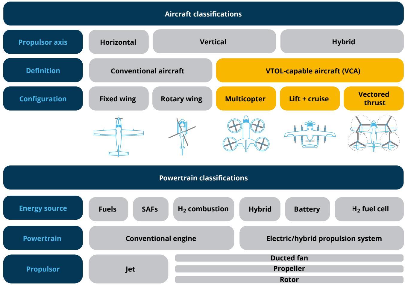
Figure 1 provides an overview of different aircraft types, including conventional aircraft and VCA, as well as their possible sources of power and propulsion systems. Aircraft types addressed by this guide are colour coded yellow.
Figure 1: Aircraft and powertrain classifications
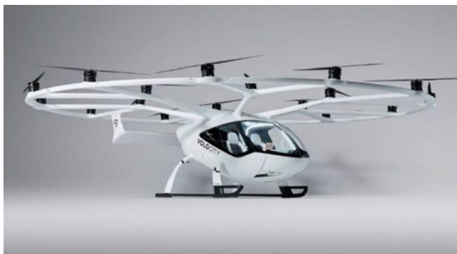
Multicopter (pure lift)
A multicopter is a VTOL-capable aircraft (VCA) with more than two lift-generating propulsors and with no fixed-wing surface for horizontal flight.
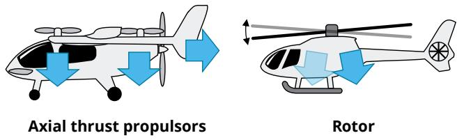
Current discussion within the AAM industry has suggested that a multicopter should be labelled as an axicraft. The rationale is based on the way lift is only generated along the propulsor axis (axial thrust). This is different from rotorcraft (helicopters or gyrocopters), where lift produced by the rotor can be tilted to direct thrust along, and off, its spin axis.
Figure 2: Thrust control: axial thrust propulsors versus rotor
Examples of multicopter VCA are the eHang EH216-S and the Volocopter VoloCity.
Figure 3: VoloCity Volocopter (image www.volocopter.com)
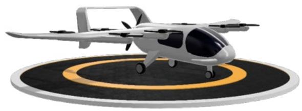
Lift plus (+) cruise
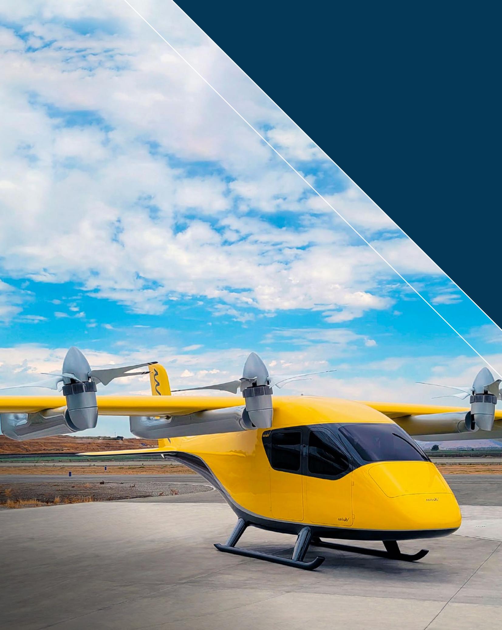
Lift plus (+) cruise VCA have a set of propulsors for generating lift for vertical flight and an additional set of propulsors combined with a fixed-wing surface for cruising in horizontal flight. It is a popular VCA design concept as there is no need for complex titling mechanisms for vectored thrust. Having a fixed wing for cruise provides better range than can be achieved by a pure multicopter. Examples of lift + cruise VCA are the Wisk Generation 5 (Cora), Eve Air Mobility’s EVE-100 and Beta’s ALIA-250. Below is the CASA reference VCA – an example of a fictitious lift + cruise VCA.
Figure 4: Example of a lift + cruise VCA
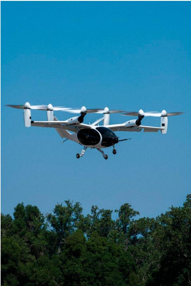
Vectored thrust
Vectored thrust VCA have propulsors that can change the direction of thrust during flight, enabling a transition from vertical to horizontal flight. The thrust propulsors provide thrust for both lift and for cruise, either by having the propulsors themselves tilt or by having the wing (with propulsors attached) tilt. Examples of vectored thrust VCA are the Joby S4 and AMSL Aero’s Vertiia.
Figure 5: Joby S4 (image www.jobyaviation.com)
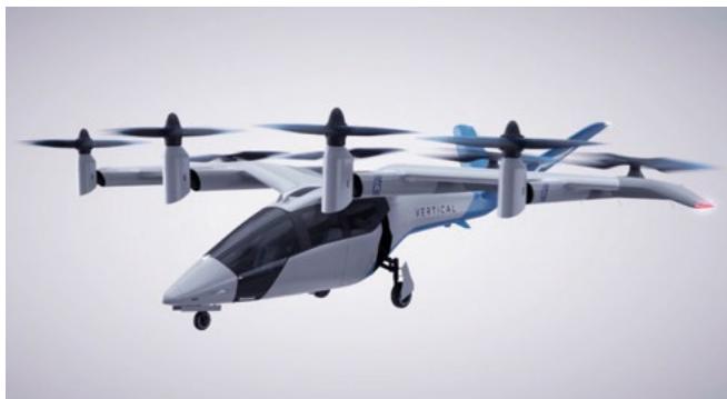
There is technically a subcategory of vectored thrust that is a lift (axial thrust) plus vectored thrust. This is a popular design configuration, where we see a high winged aircraft with a series of tilting propulsors in front of the wing augmented, during vertical procedures, by a series of lift propulsors behind the wing. Examples of this lift + vectored thrust configuration are the Vertical Aerospace VX–4, Wisk Gen 6 and Archers Midnight.
Figure 6: Vertical VX–4 (image www.avweb.com)
Vertiports – overview
Vertiports are an important infrastructure element of the advanced air mobility (AAM) ecosystem. Existing airports and heliports will continue to be used, however, there will eventually be a requirement for new infrastructure to accommodate emerging VCA types. A vertiport is different from a heliport (which can accommodate all vertical lift aircraft) as a vertiport facility will exclude use by helicopters.
Key driver for new infrastructure
The majority of VCA will be electrically powered and are therefore expected to generate less noise than traditional powered aircraft. The AAM industry wants to operate in urban areas. Typically in these areas, the construction of a heliport would not be accepted by the public, due to the noise associated with helicopter operations. Lower noise VCA present a viable alternative option, thus the requirement for vertiports.
Location
Some vertiports may be situated in large open areas that can accommodate runway-type final approach and take-off areas (FATOs). Others will be situated on small sites within a congested urban environment that are inaccessible to traditional fixed wing aircraft. These areas are where VCA can demonstrate their unique benefits and advantages.
Size
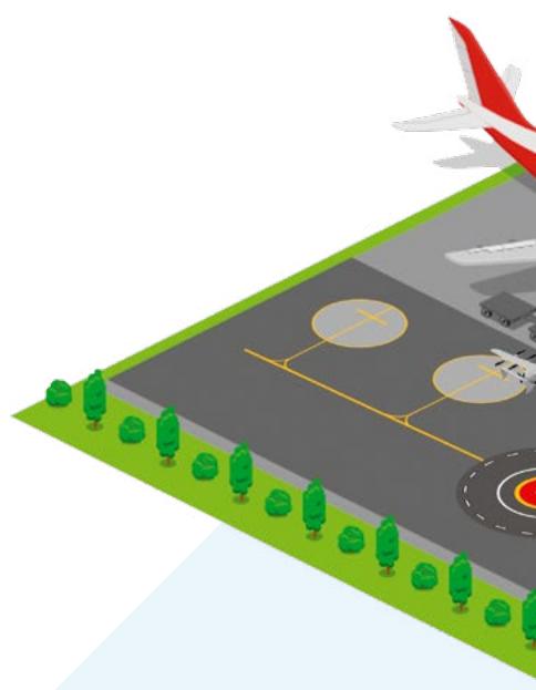
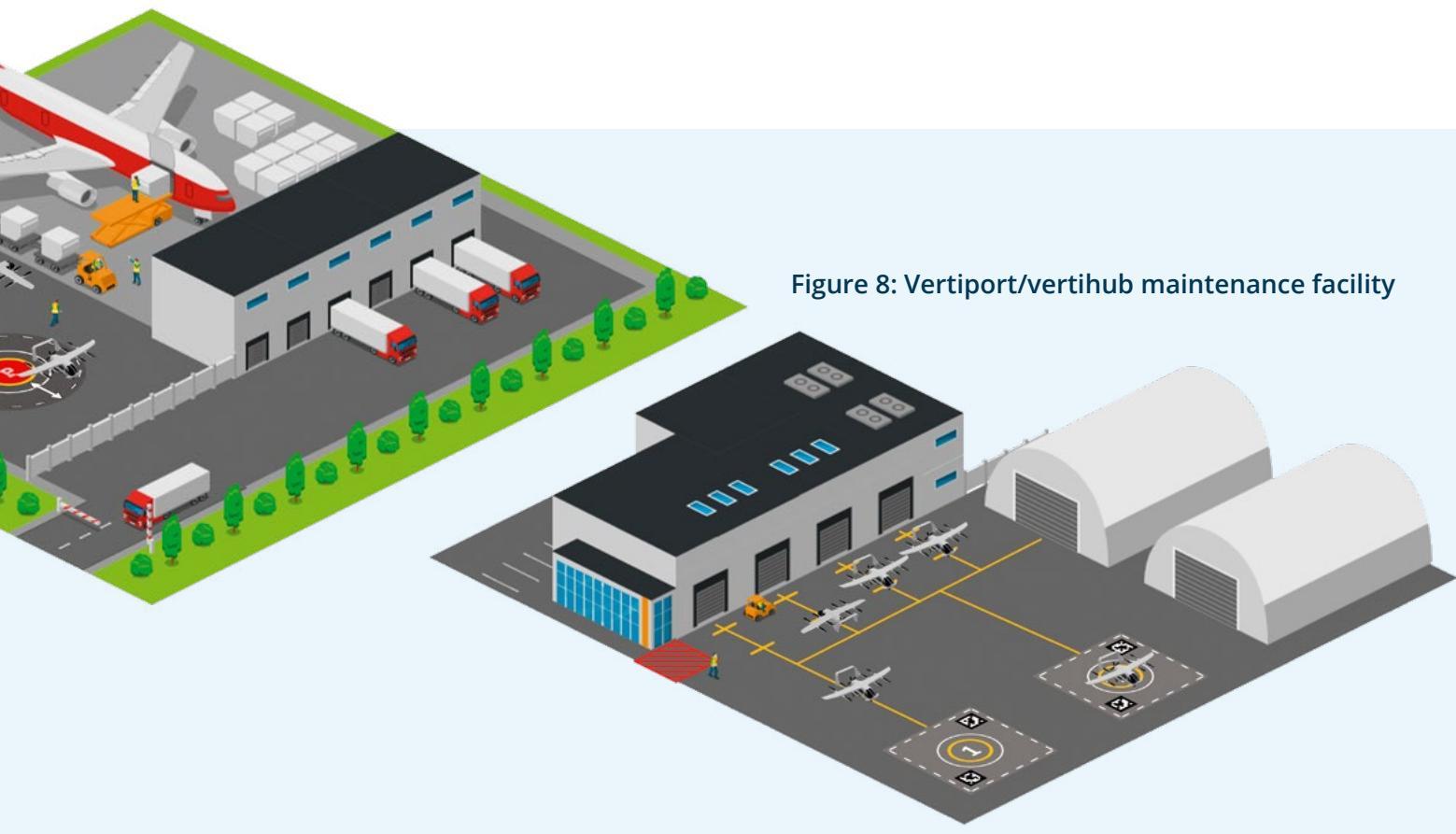
The size of a vertiport will need to suit the VCA types that will operate from it. Sizes will vary from small vertiports, with space for one aircraft and minimal infrastructure (vertistops), to large vertiports with infrastructure that can accommodate multiple aircraft. These vertiports would have facilities to accommodate larger passenger numbers and freight, with some large enough to offer maintenance and storage facilities for fleets of aircraft (vertihubs).
Figure 7: Vertiport located at a freight handling facility
Why do we need vertiport specifications when we already have heliport standards?
Vertiport specifications provide a clear separation between building a facility for all vertical lift aircraft (a heliport) and a facility that excludes helicopters (a vertiport).
This will give the AAM industry an opportunity to demonstrate to the community that a vertiport (catering only for VCA) may be more desirable than a heliport. If communities are going to accept AAM as an industry, then gaining this ‘social licence’ is vitally important. With the guidance for vertiports clearly excluding the use of helicopters then we hope that local councils and communities will be more accepting to AAM in their localities.
Also, vertiports are unlikely to cater for conventionally fuelled aircraft (for example, jet fuel or Avgas) and may not require liquid fuelling facilities or liquid fuel fire-fighting equipment. The International Civil Aviation Organization’s (ICAO) guidance for heliports (ICAO Doc 9261) recommends operators have access to firefighting foam, with quantities proportional to the size and complexity of their operation. The guidance also includes suggested deck designs which allow for safe drainage of liquid fuel from the surface. This is known as a passive fire-retarding system. Current research suggests foam and passive fire-retarding decks may be ineffective against lithium battery fires. Instead, vertiports will more likely need to be able to deliver high quantities of water for an extended period to cool runaway batteries. Future guidance will cover emergency response requirements for vertiports.
Table 1: Heliports versus vertiports
| Heliports | |
| perceived as noisy | expected to be quieter |
| hydrocarbon-fuelled aircraft often have fuelling facilities so need to meet the requirements to contain and fight | unlikely to cater for hydrocarbon-fuelled aircraft so won't need to consider such fire-retarding systems a hydrocarbon-based liquid fuel fire – for likely to need to provide large quantities |
| existing stigma of undesirable noise, which is not welcome in the community | runaway batteries VCA operators and manufacturers will need to demonstrate that VCA may be more desirable in the community |
Combined vertiports/heliports
If VTOL-capable aircraft (VCA) and helicopter operations are required at a single facility, the facility would need to comply with both heliport and vertiport specifications.
Vertiport site selection – considerations
Vertiport operators will need to consider many factors, including those that are outside CASA’s remit. CASA may only provide guidance on aviation safety matters, so vertiport operators will need to reach out to many other agencies and entities to cover all the different considerations. The following table shows sample considerations and suggested agencies to contact.
Table 2: Considerations for vertiport operators, and the relevant agencies
Sample considerations for vertiport operators
CASA
Airservices
Department of Infrastructure
Department of Environment
Home Affairs
Australian Communications and Media Authority
Bureau of Meteorology
Vertiport operator
State & local governments
Aviation safety – vertiport design, VCA certification, pilot licensing
Airspace and traffic management, published information
Aircraft noise certificates
Wildlife habitats, migratory path impacts
Physical and cyber security, screening
Communication & data – approvals, bandwidths & infrastructure
Weather recording and reporting
Land use planning approval (including noise and environmental impacts), zoning, existing transport networks, community impact and acceptance, emergency response
Vertiport concept (agnostic or bespoke ), design, layout, energy storage, local community engagement, emergency response, ground handling, OLS design and monitoring
Influences on vertiport design
Aircraft type
The types of aircraft that will operate from the vertiport will be one of the most important considerations in influencing vertiport design. Many of the design considerations (for example size, surface, layout) will be determined by the VCA design type (Design VCA), a concept described in detail later in this publication. A vertiport design that supports all VCA types would be an optimal approach.
VCA power source
Figure 9: A VCA parked at a vertistop being charged
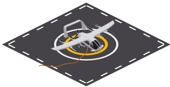
VCA power sources will influence different aspects of vertiport design. These include:
power grid impact and peak power availability
under apron, or on apron services, for on-stand charging or fuelling
storage area design and location for battery swapping vehicles
hydrogen fuel storage requirements
emergency response equipment – for example, roof top hydrants.

CASA will provide guidance on considerations for emergency response in future guidance material.
VCA manufacturer information
VCA manufacturers and operators should be an integral part of the discussion regarding the design of a vertiport. Manufacturers and operators should share the following information:
aircraft performance capabilities and limitations
aircraft dimensions and specifications
flight characteristics
how an aircraft handles in turbulence, inclement weather and crosswinds
g-loading and passenger comfort during landing, take-off and taxi
downwash and outwash modelling
equipment requirements
types of aircraft power cell – for example, battery, hydrogen or hybrid
recharging facilities and methods – for example, battery swaps versus on-aircraft charging
emergency response requirements
ground service equipment – for example, steps, tugs or other towing devices
maintenance of VCA
facilities for scheduled and unscheduled maintenance
the location of service centres and their proximity to the vertiport if not on site.
Downwash and outwash considerations
A potential hazard for vertiport operations will be the downwash and outwash from VCA operating in and out of the vertiports. Currently, there is limited operational information on VCA downwash and outwash characteristics. Vertiport operators and designers will need to work closely with VCA operators, manufacturers or other sources of research to obtain this technical data. VCA manufacturers will probably publish downwash and outwash data similar to that available to airport designers when they assess jet blast areas.
Figure 10: Concept of possible downwash and outwash data
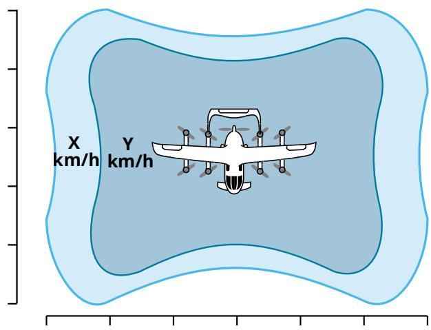
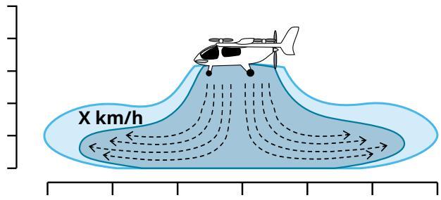
Vertiport operators and designers should assess the risk of possible injury or damage due to downwash, outwash and turbulence. This may include effects on locations under or near the approach and departure paths, both within and outside the boundary of the vertiport. Risks include:
injury to vertiport staff, passengers and the public
damage to other aircraft operating or parked at the vertiport
damage to buildings and structures
damage to vehicles
damage to equipment and utilities.
Localised downwash and outwash characteristics at a vertiport will be determined by local operational experience. Warning notices should be posted in appropriate locations to inform and warn of the dangers.
Downwash protection zone
A recent version of the Heliport Manual by ICAO includes a new section that focuses on the hazards of downwash and outwash. It has introduced the concept of a downwash protection zone. This area is specifically designed for the protection of the general public, other aircraft and those working in the vicinity of aircraft. The manual also provides new information on downwash and outwash, which quotes different caution and hazard limits for peak wind velocities.
Other systems of assessing wind comfort are also readily available online. For example, the Lawson Comfort Criteria (2001), which provides a baseline of generally acceptable wind velocities for the public.
Designing a vertiport
The Design VTOL-capable aircraft (Design VCA) concept 16
A building block approach to vertiport design 17
Obstacle limitation surfaces 24
Visual aids 31
The Design VTOL-capable aircraft (Design VCA) concept
Before considering the details of vertiport design, it is essential to understand the concept of a Design VTOL-capable aircraft (a Design VCA) as it influences the dimensions for the physical infrastructure and airspace above and around the vertiport. The Design VCA is an imaginary aircraft that embodies the critical characteristics of every aircraft that will operate at the vertiport.
Suggested parameters for the Design VCA
The Design VCA should incorporate the characteristics of all the anticipated VCA that will operate at the proposed vertiport. For example:
the largest diameter (the Design D)
the highest maximum take-off weight (MTOW)
the widest undercarriage width (UCW)
the longest take-off or landing distances
the most critical obstacle avoidance criteria
the most critical downwash and outwash criteria.
Figure 11 is an example of how Design VCA parameters can be derived from the possible VCA types that will operate from the vertiport.
Figure 11: How to derive the Design VCA parameters
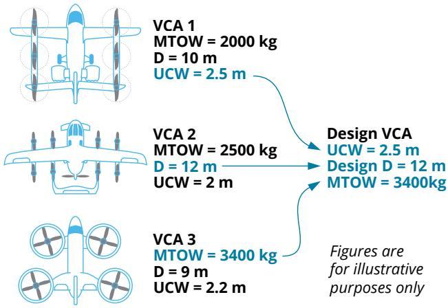

The diagram above is only an example of some of the parameters to be considered when formulating Design VCA specifications. Other criteria will also need to be considered and there can be more than one Design VCA for different facilities within a single vertiport.
Implementing the Design VCA
The example vertiport in Figure 12 demonstrates how to allow for two different Design VCA at one location.
The example has two terminals, each operating a specific VTOL aircraft. The vertiport has a single final approach and take-off (FATO) area that has been built using a Design D of 12 meters, as the Design VCA for the FATO area should have the most critical (largest) Design D of the two VCA.
Figure 12: Example vertiport design using two Design VCA
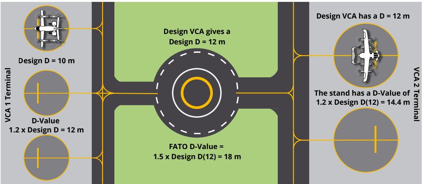
The taxi-routes and the stands leading to the VCA1 terminal have been built with a D-value based on a Design D of 10 m (from the Design VCA) and the characteristics of VCA1.
On the other side of the vertiport, the taxiways and stands leading to the VCA2 terminal are built with a D-value based on a Design D of 12 m and characteristics of VCA 2.

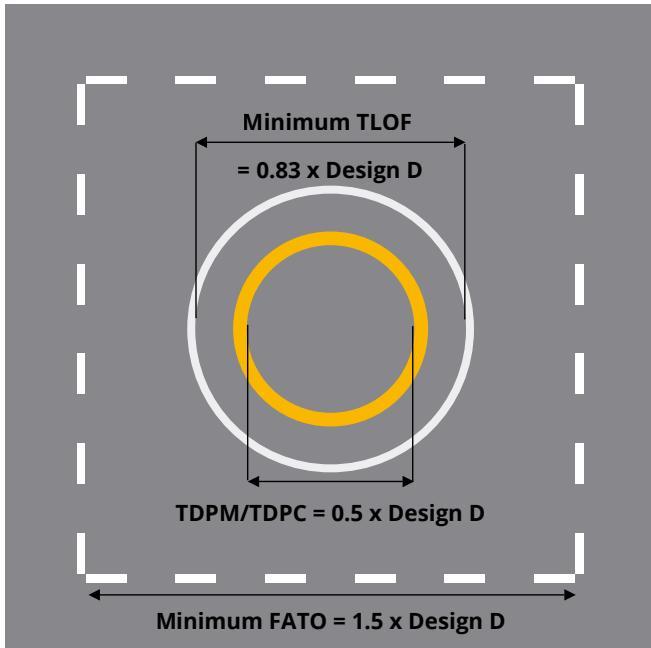
The term D-value is used for the dimension of a facility. For example, the D-value for size of a FATO (as specified in the AC) is 1.5 x Design D of the largest VCA.
Future-proofing the vertiport design
Future-proofing the vertiport design could prove challenging as the initial Design VCA used in a particular vertiport project may be different to the aircraft that operate in 5 to 10 years’ time. The risk is our inability to foresee the long-term operational model for vertiports and the future aircraft types that will operate from them. This might mean needing to restrict operations or needing to completely redesign and rebuild the vertiport so it can accommodate the new VCA types.
The introduction of the Airbus A380 is a good example: many airports around the world had to redesign aprons, taxiways and runways for an aircraft type that was significantly larger and heavier than anything envisaged when the airports were designed and built.
A building block approach to vertiport design
The concept of advanced air mobility (AAM) relies on an ecosystem of many landing sites that vary in location and design. This will range from a major vertiport with multiple stands and FATO areas, to a single pad vertistop in a semirural location. As such, the guidance for their design also needs to be flexible. CASA has taken the approach of looking at each of the vertiport physical components as building blocks consisting of essential and optional components.
Essential vertiport components
Regardless of size, a vertiport should have at least one final approach and take-off area (FATO) and one touchdown lift-off area (TLOF).
Figure 13: Basic dimensions of the FATO and TLOF
Final approach and take‑off area (FATO)
The FATO has two main purposes:
to provide a visual reference of the vertiport from the air
to provide an area of containment for a VTOL-capable aircraft (VCA) in the event of a deviation, such as a rejected take-off.
The dimensions of the vertiport’s FATO will be determined by the aircraft types that it needs to support. Using the Design VCA, the length and width of the FATO will be either:
1.5 times the Design D
the distance that has been specified in the aircraft flight manual for the VCA to conduct a rejected take-off (the rejected take-off distance required).
Solid FATO
The FATO should be solid. This is to ensure that, in the event of a critical failure during take-off, the landing of the VCA will be contained and supported until the VCA stops.
Current heliport guidance allows for a FATO to be non-solid. This is supported by many years of helicopter performance data and an understanding of their capabilities under certain circumstances. This includes helicopters operating with one engine inoperative and auto rotation capabilities. No such historical operational information is available for VCA.
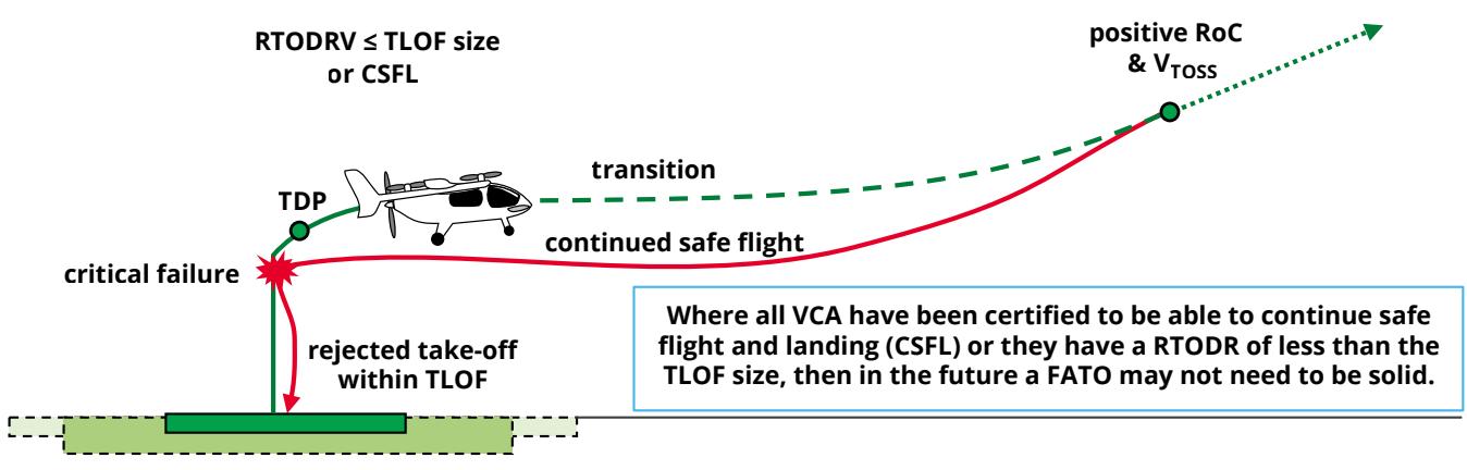
Future guidance materials may allow non-solid FATOs or have smaller FATO size requirements if:
VCA are certified and shown to be able to continue safe flight and landing (in the event of a critical failure)
their required distance during a rejected take-off is less than the current FATO specifications cater for.
Figure 14: FATO size versus rejected take‑off distance requirements
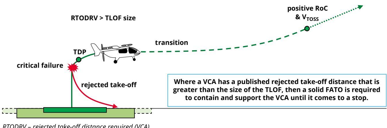
RTODRV – rejected take-off distance required (VCA)
Like a runway, a FATO may only be occupied by one aircraft at a time. Once occupied, the FATO is not available for landing or take-off by another VCA until the first aircraft is clear of the FATO protection area.
The FATO should be free of all but essential objects, such as visual aids (lights) or emergency equipment like in-deck firefighting nozzles. These items should not be higher than 5 cm above the FATO unless the TLOF is accessed by a taxiway; then they should be flush mounted.
Elongated FATOs
A FATO size is sometimes determined by the rejected take-off distance required. This means that the length of the FATO sometimes needs to be greater than 1.5 times the Design D. The vertiport may operate many VCA, but if one of the VCA requires a FATO longer than 1.5 of its D, then this will be the VCA that determines the FATO length.
Figure 15: An elongated FATO
In the above fictitious example, the VCA has a rejected take-off distance that requires a FATO length greater than twice its width. These departure directions are bi-directional in opposite directions. If the departures were omnidirectional, then the FATO would need to be larger or there would need to be additional operational procedures and restrictions.
Touchdown and lift-off area (TLOF)
The touchdown and lift-off area (TLOF) is required to provide a safe touchdown location for VCA. This may be within the FATO or a stand. (A stand is a location within a vertiport where an aircraft can be parked, passengers can embark and disembark, or maintenance can be performed.)
The main purpose of a TLOF is to contain the VCA undercarriage. The minimum dimensions of a TLOF should be 0.83 times the Design D. This is derived from heliport recommendations which are based on the study of helicopter designs.
Figure 16: Minimum and oversized touchdown and lift-off area (TLOF)
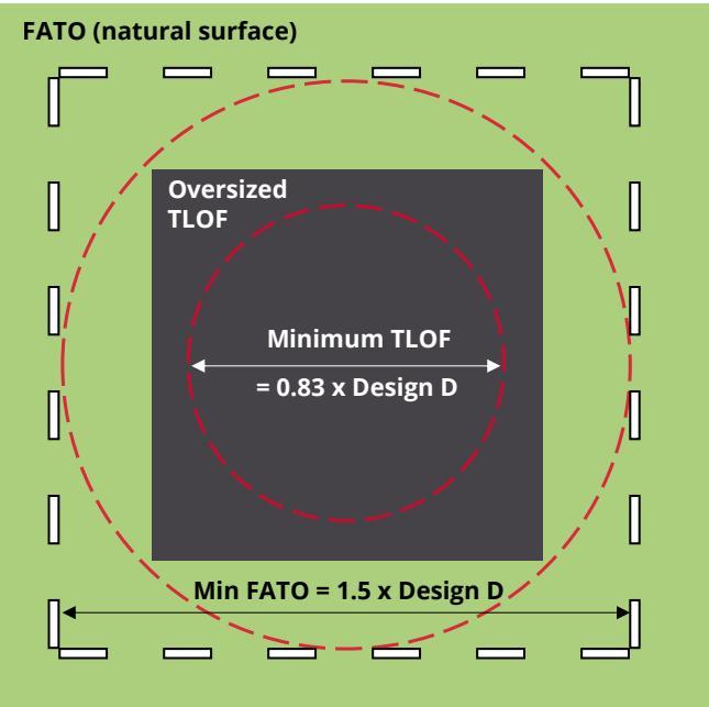
Illustration only, not all recommended markings shown
Based on the current understanding of VCA designs, this minimum dimension will accommodate the undercarriage of the majority of VCA currently in development. If a size larger than 0.83 times the Design D is required, vertiport operators can have an oversized TLOF. There are no upper size constraints other than cost and space availability.
The TLOF should be completely free of obstacles regardless of size.
FATO protection area (FPA)
The FATO protection area (FPA) is an area extending beyond the FATO set aside to ensure that there are no obstacles encroaching the FATO.
For heliports, this is known as the safety area. However, for vertiports, it has been decided to move away from this terminology due to potential confusion with general health and safety requirements. FATO protection areas are covered in more detail later in this guide.
Vertiport movement areas
Vertiport movement areas are prepared for the ground movement of VCA or VCA ground handling equipment such as tugs. They include:
the final approach and take-off area (FATO)
the touchdown and lift-off area (TLOF)
taxiways
aprons.
Movement area surfaces should:
be free of obstacles, including transient (for example, wind-blown) debris
have sufficient strength for the expected static (parked vehicle) and dynamic (emergency landing) loads
be smooth and free of irregularities (lumps and bumps)
provide enough friction to ensure aircraft and vehicles have good grip and braking performance
be resistant to downwash and outwash effects from VCA
have a shape or contour to ensure effective drainage while still ensuring the safe control and stability of VCA when touching down, lifting off or manoeuvring generally
not have a surface slope exceeding 2% (longitudinal slopes on a taxiway may be not more than 3%).
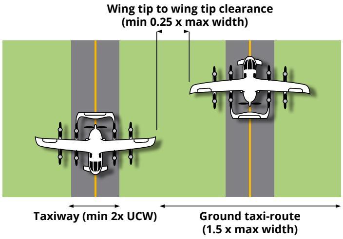
Figure 17: Vertiport taxiway clearance dimensions
Optional vertiport components
Taxiways
Vertiport taxiways allow VCA to taxi under their own power or to be towed. Taxiway dimensions are based on the width of the widest VCA undercarriage that will be operated from the vertiport. In cases where large vehicles and other pieces of ground servicing equipment are to be used, these dimensions will also need to be considered. Clearance distances between VCA on the taxiways and objects, for example parked aircraft, are also an important design consideration:
Taxiways should be at least two times the undercarriage width of the Design VCA.
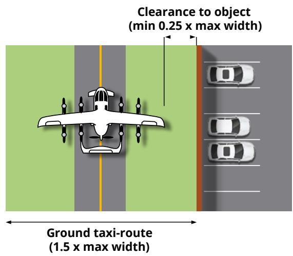
The distance between a VCA and an object should be at least 0.25 times the maximum width of the Design VCA.
The distance between the wingtips of two VCA should be at least 0.25 times the maximum width of the Design VCA.
Figure 17 below demonstrates required taxiway clearances.
Taxi-routes
A taxi-route is the protected area surrounding a taxiway and is a buffer area for VCA taxiing on the taxiway. It is the equivalent to a taxiway strip at a conventional aerodrome.
There are two types of taxi-routes:
| Type | Purpose | Width |
| Ground taxi- | provide protection | 1.5 times the maximum |
| routes | for taxiways that only / accommodate | width of the |
| ground taxing VCA and ground d vehicles | Design VCA | |
| Air taxi- routes | provide protection | 2 times the |
| for taxiways that | maximum | |
| accommodate air | width of the | |
| taxi operations | Design VCA |
Note: For taxiway dimensions, maximum width is used. This is not necessarily equal to the D.
Figure 18: Taxi-route and taxiway dimensions
Air taxi-route = 2 x overall width
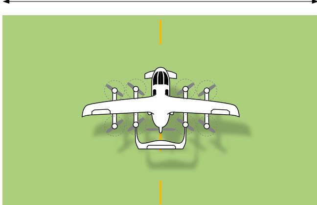
For vertiports accommodating air taxi operations (airborne taxiing of a VCA), air taxi-routes will need to be wider than ground taxi-routes to allow for the potential sideways movement of the VCA.
Air taxiing of helicopters is conducted at a height of not more than two times D above the ground at a speed of less than 20 knots. It is expected that VCA air taxiing will have similar flight performance requirements.
The ground beneath an air taxi-route may be an actual taxiway, or it may be another surface. In both cases it should be:
resistant to downwash and outwash effects
free of non-essential objects
a surface on which a VCA can conduct a forced landing.
Stands
Stands are areas that may be provided to permit the safe loading and off-loading of passengers and cargo, as well as the servicing of the VCA, without interfering with other traffic.
Stands should all:
provide a space to safely conduct turn-around operations
be free of obstacles
have sufficient strength to support the VCA, ground servicing equipment and personnel
• be free of irregularities (i.e. should be smooth)
have a surface with sufficient friction to prevent skidding or slipping
be designed to ensure it is safe for the personnel working around the aircraft and for the passengers embarking and disembarking the aircraft.
There are two ways to design stands for a vertiport:
stands based on the heliport concept using the value of Design D (D-value stands)
stands based on the geometry of the aircraft, like at traditional airports (geometry-based stands).
Figure 19: D-value based stands and a geometry-based stand
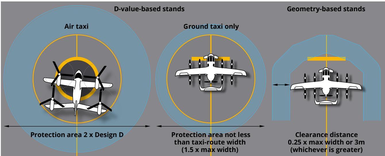
D-value stands are the circular stands that we see at heliports. They are designed to be omnidirectional to accommodate a helicopter turning itself into the wind. On aprons with multiple stands, these will often become taxi-through type stands placed next to each other.
D-value stands require an additional protection area. This gives a larger area requirement than the geometry-based stand design. This requirement is based on a typical helicopter conducting a powered taxi to the stand, either on the ground or by air-taxi.
Geometry-based stands are limited to operations where access to the stand is by ground taxiing or by being towed onto the stand. This provides increased safety because the hazards associated with downwash and outwash are significantly reduced or eliminated when the VCA can taxi without the need to produce lift. There is also less risk of a deviation from the centreline during ground taxiing or towing.
Designing geometry-based stands requires an imaginary boundary of either 3 m or 0.25 times the maximum width of the Design VCA (whichever is greater). This should then be used to work out the space needed between stands, buildings and other objects.

The 3 m or 0.25 times maximum width figures above apply to VCA with a maximum width that is less than 18 m. This covers the majority of VCA currently in development. If VCA with widths greater than 18 m are developed, then a minimum clearance distance of 4.5 m will apply.
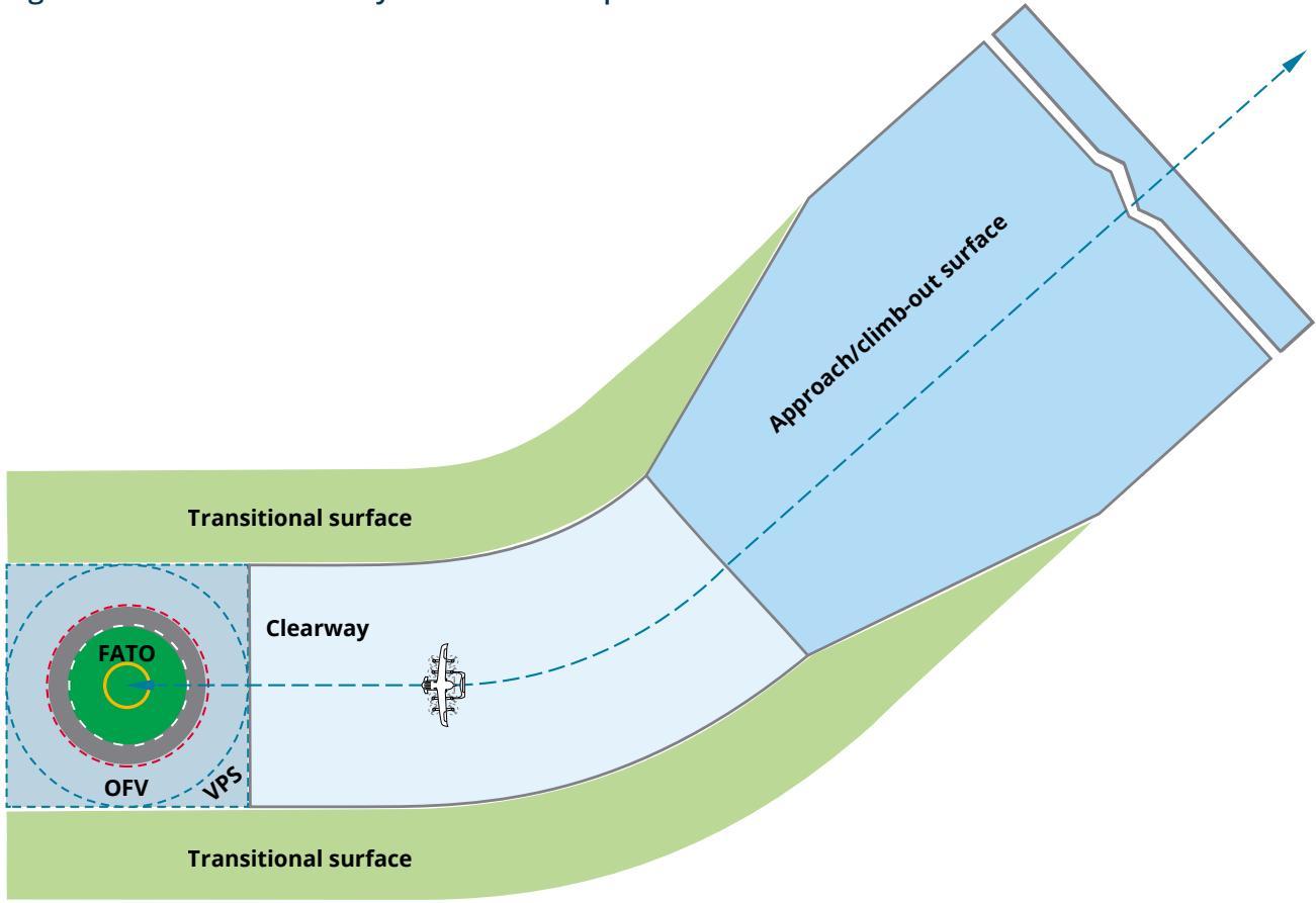
Obstacle limitation surfaces
A vertiport operator needs to be able to ensure that the vertiport has safe airspace that can be kept free from obstacles such as buildings, cranes or other structures. This is achieved by establishing a series of obstacle limitation surfaces (OLS) that define a volume of airspace around and above the vertiport and its surrounds.
OLS are designed to protect VCA performing visual approach-to-land or take-off procedures below 152 m above the elevation of the FATO. They comprise:
origin surfaces
approach/climb-out surfaces
transitional surfaces.
OLS origin surfaces
OLS origin surfaces are the protection surfaces immediately around the FATO from which the rest of the surfaces are built. They include FATO protection areas, vertical protection surfaces and vertiport clearways.
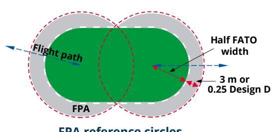
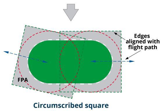
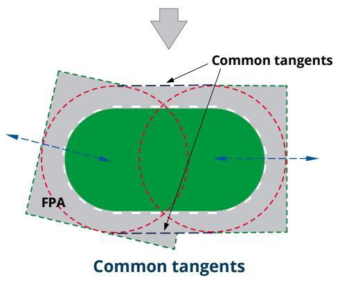
The FATO protection area (FPA) is an obstacle-free space surrounding the FATO. It provides extra protection to an airborne VCA if it experiences a variation in flight path (for example, caused by a wind gust). The FPA design is based on simple geometry using FPA reference circles, circumscribed squares and common tangents:
Figure 20: FATO protection areas – reference circles, circumscribed squares and common tangents
| Part | DescriptionDraw a final approach and take-off protection area(FPA) circle, centred on the FATOThe FPA reference circle has a radius of half the FATOwidth plus the greater of:•3mor0.25 Design D.If you have an elongated FATO, draw the FPAreference circle for each FATO end. |
| FPA | |
| reference | |
| circles | |
| Circum- | |
| scribed | |
| squares | |
| Common With an elongated FATO, the protection area (FPA)tangents needs to encompass the full length of the FATO. Thisis done by drawing direct common tangents betweenall the FATO protection area reference circles. | |
Building the FPA for a FATO without vertical procedures
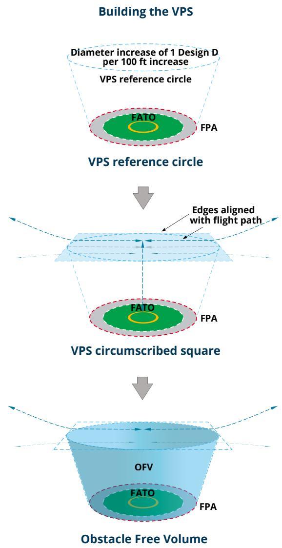
Vertical procedure surface (VPS)
For a FATO that supports vertical procedures, the FATO protection area is just the reference circle. The closer the VCA is to the FATO during landing and take-off phases, the slower and more precise the movements of the VCA should be. Procedures therefore require a protection surface that increases in size as the distance from the FATO increases.
Figure 21: Building a vertical procedure surface
| Part Description | |
| VPS Draw a reference circle above andReference centred on the FATO. The diameter ofcircle the reference circle is determined by itsheight above the FATO.For every 100 feet above the FATO,the diameter of the VPs referencecircle increases by 1 Design D from thediameter of the FPA reference circle.For example: a VPs height of 20 feetwould mean a reference circle that is0.2 times the Design D larger than theFPA reference circle. | |
| circle | |
| VPS | In the same way as for the FAToprotection area, the vertical protectionsurface will require a circumscribedsquare aligned with each flight path.This will define the inner edges of theapproach/climb-out surface and loweredges of the transitional surfaces. |
| circum- | |
| scribed | |
| square | |
| Obstacle | The obstacle-free volume is the spacethat is created by the truncated conethat is formed between the referencecircle of the FATO protection area (FPA)and the reference circle of the verticalprocedure surface (VPS). |
| free | |
| volume | |
| (OFV) | |
The vertical procedure surface (VPS) is an obstacle limitation surface (OLS) that is located at the height at which the VCA either begins its arriving vertical procedure, or where it ends its departing vertical procedure. This height will be determined by the performance characteristics of the most demanding VCA. For example, if one VCA has a vertical departing procedure that ends at 20 feet, and another VCA has an arriving procedure that starts at 30 feet, then the lowest, most limiting height (20 feet) is the one that needs to be protected.
The vertiport clearway
The next element for the vertiport obstacle limitation surfaces (OLS) is the clearway. The clearway is a protected surface that should be established where there is a need for a VCA to manoeuvre horizontally between the outer edge of either the FATO protection area (FPA) or the vertical protection surface (VPS), and the inner edge of the approach/climb-out surface.
Figure 22: Vertiport clearways
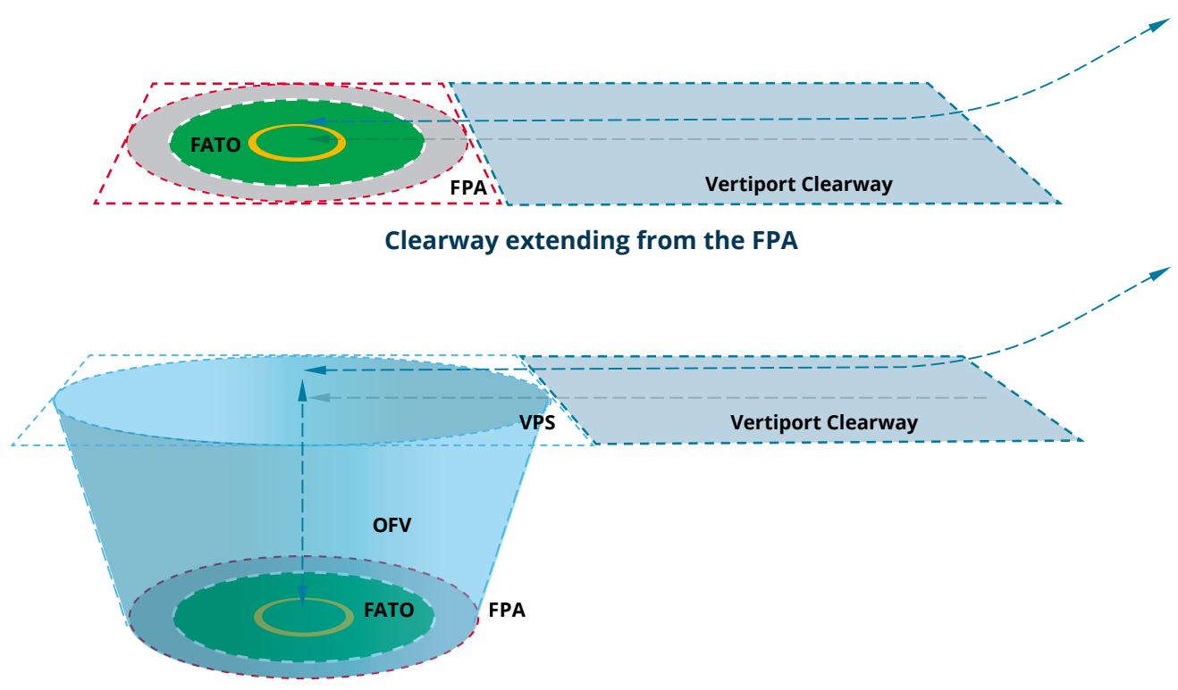
Elevated clearway extending from the VPS
The centreline of the clearway should align with the flight path and will have a width that is not less than the width of the FATO protection area or the vertical protection surface (VPS). If the flight path between the protection area or VPS and the approach/climb-out surface needs to curve or make a change in direction, then the clearway will do the same.
It is expected that clearways will become a common feature of vertiport OLS to protect VCA as they transition from vertical to horizontal flight before continuing their initial climb out.
Approach/climb‑out surfaces
The approach/climb-out surface consist of an inclined plane, or a series of inclined planes, or a complex surface that slopes up from inner edge of the FATO protection area (FPA) or the vertical protection surface (VPS).
Figure 23: Approach/climb-out surface
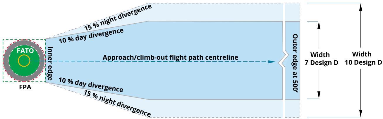
Table 3: Elements of approach/climb-out surfaces
| Part | Description |
| Inner edge | This should be coincident with, and equal to, the length of the edge of the circumscribed square of either the FATO protection area or the vertical protection surface (whichever has been established for the flight procedures relevant to the vertiport). |
| sides | Divergent The two sides of the surface extend from the ends of the inner edge and they diverge outwards uniformly at a rate of: 10% for day operations only 15% for day and night operations. The edges continue to splay outwards until they reach a final width of either 7 × Design D for day only operations or 10 × Design D for flightpaths to be used at night. |
| Outer edge | Once the surface reaches its final width, it will continue at that width until it reaches a final height of 152 m or 500 ft above the FATO. At that height, the surface ends at its outer edge, which will be horizontal and perpendicular to the flight path. |
| Surface slope | The upward slope of the surface is determined by the performance capabilities of the Design VCA and clearance requirements that are published by manufacturers in flight manuals. The slope or slopes will be measured in the vertical plane that contains the centreline of the approach/climb-out surface. |
Notes on approach/climb-out surfaces:
CASA has not received any flight performance documentation from any manufacturer currently developing VCA. Therefore, at this stage we are not providing slope guidance for the purposes of vertiport obstacle limitation surfaces design. This will be provided when actual performance data is available.
Rather than having one set of design specifications for approach surfaces and a different set for climb-out surfaces, the specifications for the surfaces are the same.
If the flight path on approach requires a shallower angle than the reciprocal climb-out, then it is the lower flight path (the approach) that needs to be protected and it would be the approach surface that forms the obstacle limitation surface (OLS).
As with the clearway design considerations, an approach/climb-out surface is aligned with a flight path. For example, if the flight path is curved then so is the OLS.
Transitional surfaces
The transitional surfaces provide protection parallel to the flight path from the FATO protection area (FPA) or the vertical protection surface (VPS) upwards and outwards.
The transitional surfaces protect an aircraft from obstacles if they move laterally from their intended flightpath.
Figure 24: Transitional surfaces
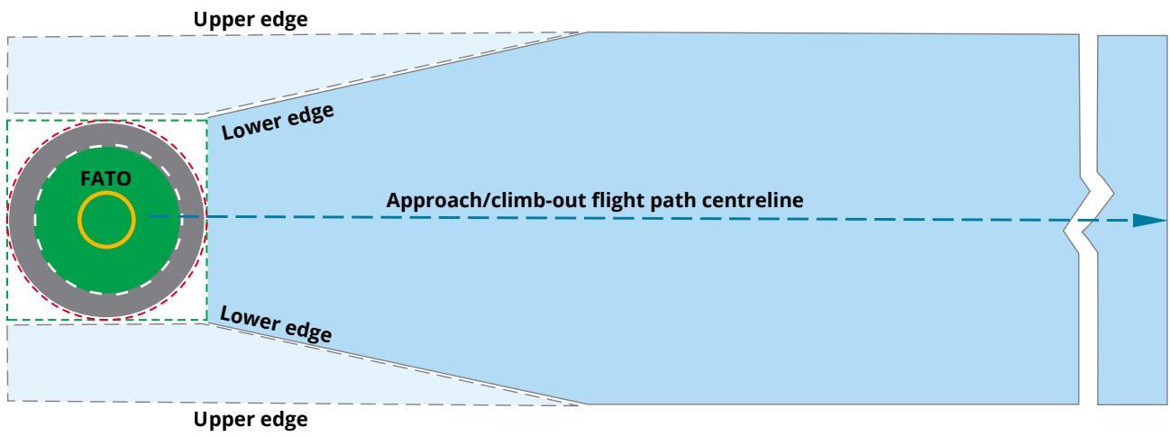
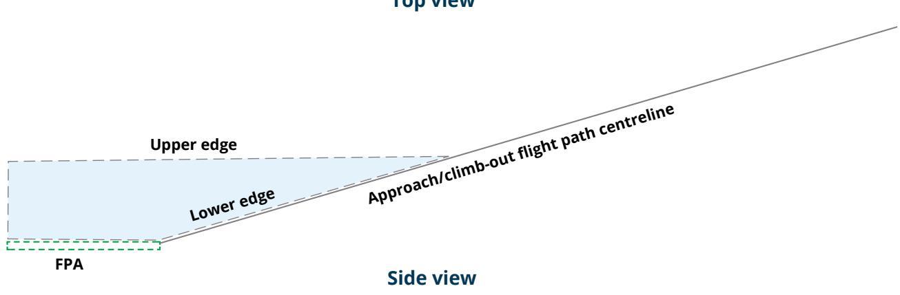
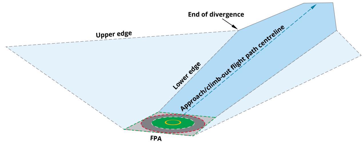
Table 4: Elements of transitional surfaces
| Part | Description |
| Lower edge | The lower edge of a transitional surface is drawn from the point where the approach/climb-out surface reaches its final width, then follows the edge of the approach/climb-out surface until it reaches the corner (where the splay meets the end of the inner edge). From there, the lower edge will follow the side of any clearway until it meets the vertical protection surface (VPs) or the FATO protection area (FPA). The last part of the lower edge will be along the edge of the VPs or FPA circumscribed square and any |
| Upper edge | common tangents. The upper edge also starts at the point where the approach/climb-out surface reaches its final width, but it then maintains a constant height whilst paralleling the flight path. The upper edge should end aligned with the lower edge. |
Notes on transitional surfaces:
Traditionally, the transitional surface has had its own separate set of dimensions. However, because of the possible combinations of slopes, turns and final widths of the approach/climb-out surfaces, the intersection with a traditional transitional surface would be complex. CASA has, therefore, simplified the process to ensure a neat OLS design.
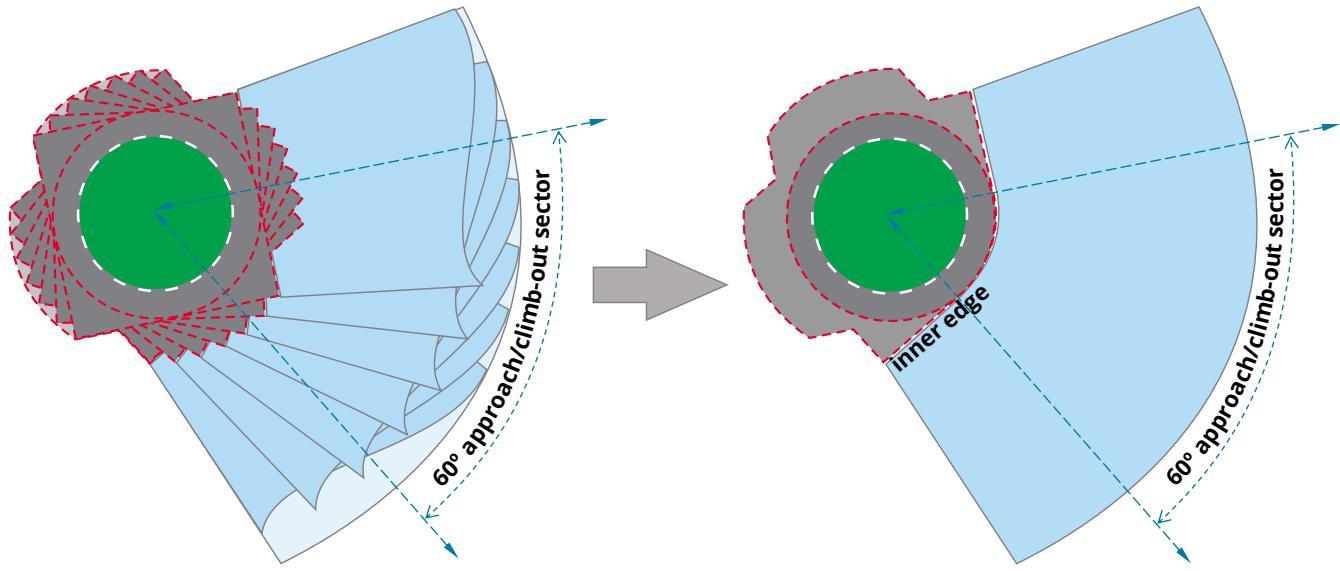
Complex obstacle limitation surface (OLS) designs
With the building block design methodology, vertiport operators and OLS designers will be able to construct OLS for more complex flight profiles if required.
The figures below show how a sector (or even an omnidirectional) approach can be designed by creating an arc of splays rotated around the FATO Protection Area (FPA) reference circle.LS for a sector
Figure 25: Building an OLS for a sector approach or departure
The figure below shows a curved clearway. Because the transitional surface follows the edge of the clearway on the bottom edge, it should be relatively straight forward to create a transitional surface for any shaped flightpath.
Figure 26: A curved clearway from a vertical procedure surface
Visual aids
In the world of aerodromes, the term ‘visual aids’ covers all the infrastructure that provides a form of information to pilots and ground operations staff around the aerodrome. These visual aids include wind indicators, ground markings and markers, lights and (on some aerodromes) movement area guidance signs.
At CASA, we tried to get a balance between outcome-based guidance and prescriptive guidance for vertiports. This is necessary for describing things like colours, shapes and patterns. We know things are going to change in this developing AAM space so we’ve tried to be flexible and to simplify the specifications wherever we could.
Advisory circular AC 139.V–01 provides details of recommended specifications for different types of visual aids. Like all the guidance in the advisory circular, the specifications are just recommendations and are not enforced by legislation. This means that a vertiport operator may choose to use other guidance material for the markers and markings, for example from the Federal Aviation Administration (FAA), the European Union Aviation Safety Agency (EASA) or ICAO. However, we hope that the guidance in the AC will give vertiport operators some flexibility in design. This will help vertiports stand out from each other visually while keeping a level of consistency so that a VCA pilot can readily identify each visual aid and its purpose.
Wind direction indicators
Wind direction indicators are an important visual aid for a pilot to assess wind direction and strength in the vicinity of the vertiport during the critical phases of flight. Considerations for the design of a wind indicator include length, diameter, colour and colour contrast. Future technologies such as non-crewed aircraft may lead to the physical wind indicators being replaced by real-time digital weather information.
Figure 27: Wind Direction Indicators
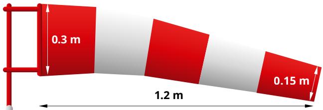
Colour/s that are clearly visible against its background
Markings and markers
The general specifications for the design of ground markings and markers have been kept very simple and outcome-based. The only general requirements are that markings and markers need to be clearly visible to the vertiport user and that they may be supplemented by reflective or refractive materials or even electroluminescent type paints if appropriate.
‘Clearly visible’ means that markings and markers need to contrast to their background or need to have a contrasting box or boundary as a background for the marking.
Markings need to be identifiable to various vertiport users, whether a pilot, operational/ ground personnel or the public.
Each marking or marker has a specific meaning or purpose:
| Marker type | Meaning or purpose | Example | |
| Flight path alignment guidance markings | used to show when there are defined approach and/or departure flight paths into or out from the vertiport provide important flight path information so should be the prominent marking where it overlaps with another marking, such as the FATO perimeter of TLOF |   | |
| FATO perimeter markings or markers | used to show the outer edge of the FATO the marking for the edge of a FATO is a dashed line required when the edge of the FATO is not self-evident for example when the FATO is part of a much larger concrete or asphalt surface should have contrast (consider a black background to the white dotted line) markers can be used where the surface cannot take a painted marking (such as grass) – they should be flush to the ground and resistant to downwash and outwash |  | |
| Marker type | Meaning or purpose | ||
| TLOF perimeter markings or markers | only recommended when the TLOF is not self-evident the marking for the edge of a TLOF is a solid line - otherwise same as FATO perimeter specifications | should be white |  |
| Aiming point markings | used when a FATO is provided but where there is no TLOF if there is a preferred approach direction, this triangular marking should be aligned to that direction should be white |  | |
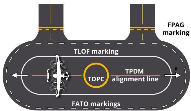
| Touchdown positioning marking (TDPM) | the marking that the pilot uses to align and position their aircraft within the TLOF (or a stand). By positioning the pilot's seat over the touchdown positioning marking, the pilot ensures that the aircraft is correctly contained, the undercarriage is safely within the TLOF and the aircraft itself is wholly contained within the boundary of the FATO includes the touchdown positioning circle used | where touchdown direction |  |
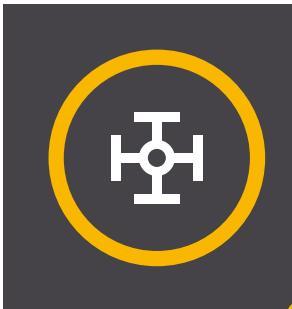
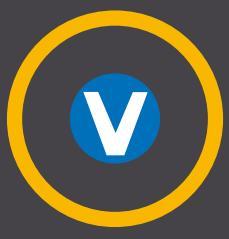
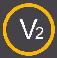
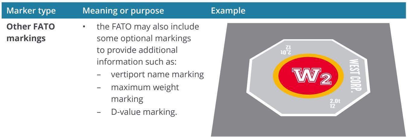
Vertiport identification marking
Meaning or purpose
doesn’t have a safety purpose; more about identification. (In the future, when VCA are autonomous, the identification will mainly be for the passengers.)
needs to identify the vertiport and be readable when aligned with the preferred approach
should be centred within the touchdown positioning circle
should not be an H or an X (already used for heliport identification)
may use ordinal numbers to identify multiple FATOs within the vertiport
Example
FAA broken wheel marking
EASA V on blue marking
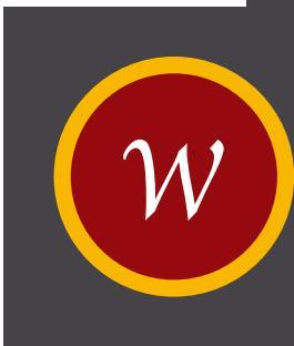
3 corporate marking examples


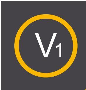
Ordinal numbering example
Taxiway and stand markings
Taxiway and stand markings provide manoeuvring guidance and are yellow in colour. The specifications for these markings have been kept consistent with traditional aerodrome (and heliport) guidance.

In general, white markings provide guidance information to the pilot for the direction of approach, acquiring the FATO area, and whether to approach to a hover (where there is an aiming point marking) or to prepare to conduct a landing. All the yellow markings take the next step and provide manoeuvring and positioning information to the pilot.
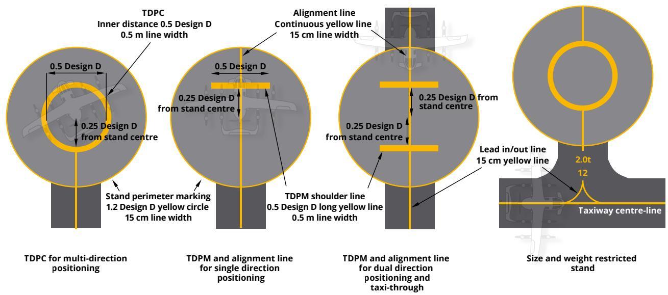
Figure 28: Stands
| Marker type Meaning or purpose | ||
| Taxiways | a continuous yellow centreline if the surface can be painted | |
| in-ground, flush-mounted markers if the surface cannot be painted (for example on clay or grass surfaces) | ||
| where there is no physical taxiway (where there are air-taxi routes), the ground under the air-taxi route should still be marked in the same way as a physical taxiway | ||
| VCA stands | the most important markings are: | |
| a touchdown positioning marking: shoulder line type is the most common and is used where the apron design is based on a single direction parking of aircraft | ||
| a stand perimeter marking: provides an indication of the edge of the stand | ||
| perimeter where the stand is designed using the Design D lead-in/lead out markings: an extension of the taxiway centrelines leading | ||
| into the stand optional markings include: | ||
| alignment lines: assist in keeping the correct alignment for the last part of the | ||
| taxi onto the stand up to the parking position a stand designation and limitation markings: provide information to pilots | ||
| taxing into the apron. They can be used to show stand numbering or to | ||
| indicate where there is a limitation on the stand such as a maximum weight limit or a maximum wingspan apron safety lines: general markings used to show a safe limit of aircraft |
Other markings
Vertiport operators may also reference other guidance for providing airside visual aids. The Part 139 Manual of Standards has several other markings and visual aids that might be suitable for a vertiport such as:
pedestrian walkways (zebra crossings)
equipment storage and equipment clearance lines
apron edge lines
movement area guidance signs (MAGS).
Vertiport lighting
CASA’s guidance on lighting in the advisory circular AC 139.V–01 is limited as our initial brief for the AC is for VCA operating in visual conditions (so lights associated only with instrument conditions were not included). However, once there is a better understanding of operations in instrument conditions, then additional lighting guidance will be added to the AC.
Traditional lighting guidance may not be appropriate
We used outcome-based specifications for light photometrics in our guidance as traditional lighting guidance may not be appropriate.
The photometrics for vertiport lights and lighting elements (including light output, vertical and horizontal distribution, and chromaticity) should be appropriate to the vertiport environment and intended operations without being visually distracting or confusing to pilots.
Traditional aerodrome lighting guidance has been based on aerodrome environments that are typically wide-open areas outside an inner city. At night, the important lights from the perspective of a pilot approaching the airport are viewed within a void of other light. However, we expect that vertiports may be in areas where:
there will be far more light pollution around the vertiport, requiring a different or stronger light output
excess light pollution from the vertiport could cause a disturbance to nearby residents in and around residential high rises.
Also, there have been many leaps in lighting technology since aerodrome lighting specifications were written and the technology is likely to continue evolving. There could be any number of different solutions to designing an appropriate lighting system for a vertiport, and one vertiport may require a different solution to another depending on the environment within which they are located and how VCA operate to and from the vertiport.
Different lights for different purposes
Light systems should follow a colour philosophy that matches a purpose of the lights with a particular colour.
| Light colour | Purpose |
| white lights | provide initial acquisition of, and guidance to, the vertiport and include the FATO perimeter lights, the flight path alignment lights orthe aiming point lights |
| yellow lights | provide alignment guidance for touching down and alignment for taxing |
| green lights | define the TLOF or provide guidance for an aircraft air-taxiing to a TLOF |
| Use of light | Description | Example | |
| Flight path alignment guidance lighting system (FPAGLS) | The FPAGLS provides an indication of available landing and take-off path directions. These are the lights that match with the alignment guidance markings and should be located within the marking as far as practicable. With the recommended minimum |  | |
| distance between the first and last of the lights being 6 m, there will be instances where | |||
| FATO perimeter lights | |||
| Aiming point lights | pilots with a visual means to acquire the FATO while on approach to the vertiport. This system is a series of six white lights located within the white line of the triangular aiming point marking, one light | ||
| located at each point and one light located between each pair of corner lights. TLOF lighting systems | There are a few options for TLOF lighting systems. The options are dependent on the locations of the TLOF. TLOFs within a FATO should by lit by green perimeter lights or yellow TDPC lighting segments, while TLOFs within a parking stand are | ||
| TLOF perimeter lighting | lit by flodlighting. Green TLOF perimeter lights should be outside, but within 0.3 m of the TLOF edge. They should be spaced evenly around the TLOF not more than 3 m apart. | ||
| Use of light Lighting | Description | Example | |
| segments and lighting elements | Lighting segments are any low-profile lighting fixture that consists of a line of lighting elements within a frame or a unit. These lighting elements could be LEDs, fibre optic cable or electro luminescent panels. There may be a single light source or there may be many. Lighting segments are used to create patterns of lights to mimic the marking they are conveying. In the case of | simplified example of a lighting segment, with three individual lighting elements. oolo 月 ≤0.1 m 0.5m | |
| Lighting taxiways and taxi-routes | Guidance is outcome-based: The centreline should be lit, preferably yellow for consistency with the touchdown positioning circle to prevent confusion with the green TLOF perimeter light. The lights should be sufficiently spaced to provide guidance. Air taxi-routes could be lit with alternating green and yellow lights to help visually distinguish between a taxi-route that does not support air-taxing (ground |  | |
| Flood lighting for stands | Light sources from multiple angles reduce the likelihood of having shadowed areas on the apron. Consider the horizontal and vertical components of the lighting to ensure the stand is adequately lit but that there is not a risk of glare to the pilots (or nearby | ||
Thinking outside the box
The lighting guidance that has been provided in the AC is generally based on historical lighting guidance for heliports as well as trying to mirror some initial guidance from a few overseas regulatory agencies. However, these historical specifications are all based on pre-existing technologies. LED technology has come a long way since there has been any update to heliport or aerodrome guidance. There is nothing in the AC that precludes a vertiport operator from looking at new technologies for lighting the vertiport so long as the specified outcomes are met.
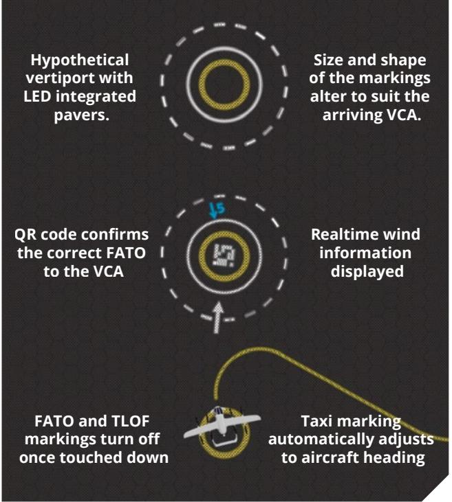
Hypothetical examples:
Example 1:
Paving technology proposed for roadways and paths is being developed that has integrated LEDs. Providing all the physical specifications such as strength, friction, drainage can be met, this could revolutionise how vertiports are marked and lit. This kind of ‘digital FATO’ could project its markings in real time to the FATO, the approach path and wind data could be displayed within the FATO area. Also, you could turn off FATO edge markings to indicate a FATO is occupied, and then bring up passenger markings to guide passengers to and from the terminal.
Example 2:
FATO information could be shared in real time with aircraft operators and aircraft in flight, allowing fine adjustment for departure, flight and arrival time to match the usage of the FATO.
Example 3:
Future fully-autonomous aircraft may mean that markings and lights will become superfluous. Visual aids are to be seen – by a pilot. Machine readable aids such as QR codes may be used on vertiports to guide aircraft. What will a future vertiport need to be able to guide a VCA safely and accurately?

Where to from here?
Advisory Circular AC139.V–01 provides greater detail of the design requirements and methods for vertiport design and should be used for actual design work.
CASA has not received (at time of publication) any flight performance documentation from any manufacturers currently developing VCA. We hope the guidance provided in the AC is specific enough to guide vertiport designers and operators in developing a safe and operationally effective facility yet open enough to promote new thinking in this evolving industry.
So, what does this mean for vertiport operators? In short, it means start talking to prospective VCA manufacturers and other stakeholders as soon as possible: the design of the vertiport may take some time.
To even start designing a vertiport, you will need to get a very good understanding of:
the sort of operations you are planning for your vertiport – both initially and in the future
• the types of VCA you want to cater for
how the flight performance of these VCA is going affect the possible flight paths
the obstacle environment that exists around your vertiport
the future development plans in the area and whether they impact the design of the vertiport.
As the industry evolves, new guidance will be produced and current guidance will be updated. Please keep in touch at the CASA emerging technologies program webpage: www.casa.gov. au/resources-and-education/publications-andresources/corporate-publications/emergingtechnologies-program.
Image: Eve Air Mobility
Appendix A – Acronyms and initialisms
| Term | Definition |
| AAM | advanced air mobility |
| AC | advisory circular |
| D | (largest) diameter (see definitions table) |
| EASA | European Union Aviation Safety Agency |
| FAA | Federal Aviation Administration |
| FATO | final approach and take-off (area) |
| FPA | FATO protection area |
| FPAGLS | flight path alignment guidance lighting system(s) |
| ICAO | International Civil Aviation Organization |
| MTOW | maximum take-off weight |
| NASA | National Aeronautics and Space Administration |
| OFV | obstacle free volume |
| OLS | obstacle limitation surface |
| RTODRV | rejected take-off distance required |
| SAF | sustainable aviation fuel |
| STOL | short take-off and landing |
| TDPC | touchdown positioning circle |
| TDPM | touchdown positioning marking |
| TLOF | touchdown lift-ff (area) |
| UCW | undercarriage width |
| VCA | VTOL-capable aircraft |
| VPS | vertical procedure surface |
| VTOL | vertical take-off and landing |
Appendix B – Definitions
| Term | Definition |
| aerodrome | an area on land or water (including any buildings, installations and equipment) which is authorised under the regulations to be used as an aerodrome for the arrival, departure and movement of aircraft |
| D | for VCA: the diameter of the smallest circle enclosing the aircraft projected on a horizontal plane, while the aircraft is in the take-off or landing configuration, with lift/thrust units turning, if applicable Note: If the aircraft changes dimensions during taxing or parking (for example, folding |
| Design VCA | wings), a corresponding D(taxing) or D(parking) should also be provided a virtual aircraft type that has the largest set of dimensions, the greatest maximum take-off weight (MTOW) and the most critical obstacle avoidance criteria of the aircraft that the vertiport, or for a defined area within the vertiport, is intended |
| Design D | to serve the D of the Design VCA |
| elongated | when used with TLOF or FATO, elongated means an area which has a length more than twice its width |
| final approach and take-off area (FATO) | for the operation of a VCA, a solid area: • from which a take-off is commenced |
| instrument meteorological conditions | • over which the final phase of approach to hover is completed means meteorological conditions other than visual meteorological conditions (see below) |
| obstacle obstacle limitation surfaces | an object (whether temporary or permanent) or part of such an object that: • is located on an area provided for the movement of aircraft • extends above a defined surface designated to protect aircraft in flight a series of planes associated with each FATO at a vertiport, which define the desirable limits to which objects or structures may project into the airspace around the vertiport so that aircraft operations at the vertiport may be conducted safely. The obstacle limitation surfaces are as follows: • FATO protection area (FPA) |
| reference circle a horizontal circle, of the specified dimension, that is centred on any intended position/flight path at or above the applicable area/surface | |
| rejected take-off distance required (RTODRV) | the horizontal distance that is required from the start of the take-of to the point where the aircraft comes to a full stop, following a critical failure that is recognised at the to take-off decision point |
| touchdown and lift-off area (TLOF) | an area where a VTOL-capable aircraft may touchdown or lift off |
| touchdown positioning circle (TDPC) | a TDPM in the form of a circle, which is used for omnidirectional positioning in a TLOF |
| touchdown positioning marking (TDPM) | a marking or set of markings that provide visual cues for the directional positioning of an aircraft |
| vertical | a take-off and landing procedure that includes an initial and/or final vertical profile. The profile may or may not include a horizontal component |
| procedure vertical | a surface at which a VTOL-capable aircraft either: |
| procedure | • begins its arriving vertical procedure |
| surface (VPs) vertiport | • ends its departing vertical procedure the highest point of the FATO, or where there are multiple FATOs, the highest point |
| elevation vertiport | of the highest FATO an area of land, water or structure that is used or intended to be used for the landing, take-of and movement of VTOL-capable aircraft |
| vertiports also include vertihubs and vertistops: • vertihub: a vertiport with infrastructure for maintenance, repair, fuelling and | |
| vertistop: a vertiport intended for take-off and landing of VCA to drop off or | |
| parking spaces for storage of VCA | |
| pick up passengers or cargo, but where there are no facilities for fuelling, | |
| defuelling, scheduled maintenance, scheduled repairs or storage of aircraft | |
| vertiport | a defined horizontal surface selected and/or prepared as a suitable area over |
| clearway | which an aircraft, capable of continued safe flight after a critical failure, may |
| operate between the FATO/VPS and the approach/climb-out surface inner edge | |
| visual meteorological conditions | meteorological conditions expressed in terms of visibility, distance from cloud, and ceiling, equal to or better than specified minima |
| VTOL-capable aircraft (VCA) | a heavier-than-air aircraft, other than aeroplane or helicopter, capable of performing vertical procedures by means of more than two lift/thrust units |
| VCA stand | a defined area that is intended to accommodate aircraft for loading or unloading passengers, mail, or cargo, fuelling/charging, parking or maintenance |
| VCA taxi-route | a defined path that is established for the movement of VCA from one part of a vertiport to another: • an air taxi-route: a marked taxi-route that is intended for air taxing • a ground taxi-route: a marked taxi-route centred on a taxiway that is intended for ground movement |
| VCA taxiway | a defined path on a vertiport that is intended for the ground movement of VCA from one part of a vertiport to another |