FAA AC 150/5390-2D 完整版
Subject: Heliport Design
Date: 1/5/2023
Initiated By: AAS-100
AC No: 150/5390-2D
Change:
1 Purpose.
This advisory circular (AC) provides standards for the planning, design and construction of heliports serving helicopters with single, tandem (front and rear) or dual (side by side) rotors.
2 Cancellation.
This AC cancels AC 150/5390-2C, Heliport Design, dated April 24, 2012.
3 Applicability.
The Federal Aviation Administration (FAA) recommends the standards and guidelines in this AC for uniformity in planning, design, and construction of heliports. This AC does not constitute a regulation, is not mandatory and is not legally binding in its own right. This AC will not be relied upon as a separate basis by the FAA for affirmative enforcement action or other administrative penalty. The standards and guidelines contained in this AC are practices the FAA recommends for establishing an acceptable level of safety, performance, and operation for heliports. Conformity with this AC is voluntary, except for the projects described in subparagraphs 1, 2, and 3 below:
Use of these standards and guidelines is mandatory for projects funded under Federal grant assistance programs, including but not limited to the Airport Improvement Program (AIP) and Coronavirus Aid, Relief, and Economic Security (CARES) Act Airport Grants program. See Grant Assurance #34. Heliport sponsors should familiarize themselves with the obligations and assurances that apply to each grant program from which they obtained grant funds.
This AC is mandatory, as required by regulation, for projects funded by the Passenger Facility Charge (PFC) program. See PFC Assurance #9.
This AC has no applicability under Title 14 Code of the Federal Regulations (CFR) Part 139 due to an exemption for heliport operators per § 139.1(c)(5).
Other federal agencies, states, or other authorities having jurisdiction over the construction of heliports not funded with AIP, CARES Act, or PFC funds have discretion in establishing the extent to which these standards apply.
4 Related Documents.
ACs and Orders referenced in the text of this AC do not include a revision letter, as they refer to the latest version. See Appendix E for a list of associated publications.
5 Principal Changes.
The AC incorporates the following principal changes:
Complete reorganization of this AC:
a. Consolidated Chapters 2, 3 and 4 (GENERAL AVIATION, TRANSPORT, and HOSPITAL heliport chapters, respectively) into Chapter 2.
b. Consolidated Chapter 7 (Heliport Gradients and Pavement Design) into Chapter 2.
c. Included a separate Chapter 3 on Heliport Taxiways, Taxi Routes, and Helicopter Parking.
d. Included a separate Chapter 4 on Heliport Markings and Lighting.
e. Included a separate Chapter 7 on Heliport Site Safety Elements.
f. Added new Appendix B, Pre-designated Emergency Landing Areas (PELAs).
g. Incorporated Engineering Brief #87, Heliport Perimeter Light for Visual Meteorological Conditions, into this AC to address specific heliport lighting requirements. Heliport lighting design requirements are included in Appendix G.
Revised figures and tables to correspond with the design requirements and dimensions for GENERAL AVIATION, TRANSPORT, and HOSPITAL heliports.
Enhanced the figures to include dimensional, layout, and offset requirements.
Updated the format of the document and made minor editorial changes throughout.
Included a heliport evaluation process flow chart in Appendix F.
6 Using this Document.
Hyperlinks (allowing the reader to access documents located on the internet and to maneuver within this document) are provided throughout this document and are identified with underlined text. When navigating within this document, return to the previously viewed page by pressing the “ALT” and “ ←” keys simultaneously.
Figures in this document are general representations and are not to scale. Colors and shading used in the figures are illustrative only. Guidance on specific heliport markings is provided in Chapter 4.
7 Use of Metrics.
Throughout this AC, U.S. customary units are used followed with “soft” (rounded) conversion to metric units. The U.S. customary units govern.
8 Where to Find this AC.
You can view a list of all ACs at
https://www.faa.gov/regulations_policies/advisory_circulars/. You can view the Federal Aviation Regulations at https://www.faa.gov/regulations_policies/faa_regulations/.
9 Feedback on this AC.
If you have suggestions for improving this AC, you may use the Advisory Circular Feedback form at the end of this AC.

John R. Dermody
Director of Airport Safety and Standards
CONTENTS
Paragraph Page
CHAPTER 1. Introduction.. .... 1-1
1.1 Background.. ..... 1-1
1.2 General... .... 1-1
1.3 Facilities. . .... 1-1
1.4 Planning. ... .... 1-2
1.5 Existing Heliports. ..... ..... 1-2
1.6 Location. ............. ...................... 1-2
1.7 AC Organization. ........ ....... 1-3
1.8 Explanation of Terms...... ....... 1-3
1.9 Selection of Approach/Departure Paths.. ... 1-10
1.10 Notification Requirements. .. ..... 1-10
1.11 Hazards to Air Navigation. . .... 1-15
1.12 Federal Assistance. . ... 1-18
1.13 Environmental Impact Analyses.. ... 1-18
1.14 Terminal Facilities Design Considerations.. ..... 1-19
1.15 Zoning for Compatible Land Use. ...... ................. 1-19
1.16 Access to Heliports by Individuals with Disabilities..... ....... 1-20
1.17 State Role. ... ..... 1-20
1.18 Local Role and Building Code.. ... 1-20
1.19 Related Referenced Material.. .... 1-20
CHAPTER 2. Heliport Design... ..... 2-1
2.1 General... .... 2-1
2.2 Prior Permission Required (PPR) Facilities........... ........ 2-1
2.3 Design Approach. ..... .... 2-1
2.4 Access by Individuals with Disabilities.. ..... 2-1
2.5 Heliport Site Selection. . ... 2-4
2.6 TLOF/FATO and Safety Area Relationships. ..... 2-7
2.7 Touchdown and Liftoff Area (TLOF).. ... 2-9
2.8 Final Approach and Takeoff Area (FATO). .. 2-17
CONTENTS
Paragraph Page
2.9 Safety Area.. .. 2-21
2.10 Fall Protection and Safety Net Design.. ... 2-24
2.11 Pavement Design and Soil Stabilization. . ... 2-25
2.12 VFR Approach/Departure Paths. . .. 2-27
2.13 Heliport Protection Zone (HPZ). . .. 2-35
2.14 Wind Cone. . ... 2-35
CHAPTER 3. Heliport Taxiways, Taxi Routes, and Helicopter Parking ...... ...... 3-1
3.1 General.. .... 3-1
3.2 Taxiways and Taxi Routes....... ........ 3-1
3.3 Taxiway/Taxi Route Widths..... ...... 3-1
3.4 Taxiway Surfaces.... ..... 3-6
3.5 Taxiway and Taxi Route Gradients. ... 3-6
3.6 Helicopter Parking. . .... 3-6
3.7 Parking Position Sizes.... .... 3-13
3.8 Walkways.... ... 3-16
3.9 Fueling. ........ ... 3-16
3.10 Tiedowns.... ... 3-16
CHAPTER 4. Heliport Markings and Lighting...... ......... 4-1
4.1 General.. .... 4-1
4.2 Heliport Retroreflective Markers and Markings. .... 4-1
4.3 Standard Heliport Identification Marking... ..... 4-1
4.4 TLOF and FATO Markings.. ..... 4-6
4.5 Extended Pavement/Structure Markings for GENERAL AVIATION and
HOSPITAL Heliports. ..... .... 4-10
4.6 FATO Perimeter Markings. .... ................ ..... 4-10
4.7 Flight Path Alignment Guidance Marking.. ... 4-11
4.8 Taxiway and Taxi Route Markings..... ........................................................... 4-12
4.9 Helicopter Parking Position Markings.. ...... 4-13
4.10 Walkways..... ... 4-14
4.11 Closed Heliport. . .. 4-14
CONTENTS
Paragraph Page
4.12 Marking Sizes. .. ... 4-15
4.13 Heliport Lighting. . .. 4-15
CHAPTER 5. Helicopter Facilities on Airports... ..... 5-1
5.1 General.. .... 5-1
5.2 Touchdown and Liftoff Area (TLOF). ... 5-1
5.3 On-Airport Location of Final Approach and Takeoff Area (FATO). ... 5-1
5.4 Safety Area..... ...... 5-3
5.5 VFR Approach/Departure Paths. .. .... 5-3
5.6 Heliport Protection Zone (HPZ). ... 5-3
5.7 Taxiways and Taxi Routes..... ... 5-3
5.8 Helicopter Parking. . .. 5-4
5.9 Security. .. .. 5-4
CHAPTER 6. Instrument Operations .... ..... 6-1
6.1 General.. ... 6-1
6.2 Planning. ... ... 6-3
6.3 Airspace. .. ... 6-3
6.4 Final Approach Reference Area (FARA). .. ...... 6-3
6.5 Improved Instrument Lighting System. ... ..... 6-4
6.6 Obstacle Evaluation Surfaces. .... 6-8
6.7 Visual Glideslope Indicators (VGSI)... ..... 6-8
CHAPTER 7. Heliport Site Safety Elements ... ..... 7-1
7.1 General.... ..... 7-1
7.2 Marking and Lighting of Difficult-To-See Objects.. ..... 7-1
7.3 Safety Considerations. . ... 7-4
Appendix A. Emergency Helicopter Landing Facilities (EHLF)..... ..... A-1
A.1 General... .. A-1
A.2 Notification and Coordination. .. ... A-1
A.3 Rooftop Emergency Facilities.. .. A-1
CONTENTS
Paragraph Page
Appendix B. Pre-designated Emergency Landing Areas (PELAs) ..... ..B-1
Appendix C. Helicopter Data... .... C-1
Appendix D. Dimensions for Marking Size and Weight Limitations............... . D-1
Appendix E. Associated Publications and Resources ...... .....E-1
Appendix F. Heliport Evaluation Process Flow Chart ... .....F-1
Appendix G. Design Requirements for Heliport Perimeter Lighting ..... ..... G-1
G.1 Elevated and In-pavement Omnidirectional Helipad Perimeter Light. ... G-1
G.2 Photometric Requirements.. .. G-2
G.3 Additional Heliport Perimeter Light Requirements.. .. G-2
G.4 L-860H and L-852H Light Fixture Testing. ... .. G-3
G.5 Installation Criteria. .. .. G-3
FIGURES
Figure 1-1. FAA Form 7480-1, Notice for Construction, Alteration and Deactivation of Airports
... 1-12
Figure 1-2. Example of a Heliport Layout Plan.. .... 1-13
Figure 1-3. Example of a Heliport Location Map... ..... 1-14
Figure 1-4. Offsite Development Requiring Notice to the FAA . ... 1-17
Figure 2-1. GENERAL AVIATION Heliport – Basic Features... ... 2-2
Figure 2-2. TRANSPORT Heliport – Basic Features...... ..... 2-3
Figure 2-3. HOSPITAL Heliport (Ground Level) – Basic Features.. .. 2-4
Figure 2-4. Heliport EMI Hazard Marking.. .. 2-6
Figure 2-5. Heliport EMI Hazard Sign .... .. 2-7
Figure 2-6. TLOF/FATO/Safety Area Relationships and Minimum Dimensions . .. 2-8
Figure 2-7. Heliport Gradients and Rapid Runoff Shoulder - Load-bearing FATOs. ... 2-12
Figure 2-8. Optional Elongated TLOF and FATO with Two Takeoff Positions.. ... 2-13
Figure 2-9. Elevated Heliport: GENERAL AVIATION and HOSPITAL. ... 2-15
Figure 2-10. Elevated Heliport: TRANSPORT . .... 2-16
Figure 2-11. Additional FATO Length for Heliports at Higher Elevations .. ... 2-19
Figure 2-12. Non-load-bearing FATO and Safety Area over Water: GENERAL AVIATION and
HOSPITAL Heliports .. ... 2-23
Figure 2-13. Non-load-bearing Safety Area over Water: TRANSPORT ... ... 2-24
Figure 2-14. Helicopter Landing Gear Loading: Gradients and Pavement ..... ..... 2-26
Figure 2-15. VFR Heliport Approach/Departure and Transitional Surfaces. .. 2-28
Figure 2-16. VFR Curved Approach/Departure and Transitional Surfaces – GENERAL
AVIATION and TRANSPORT Heliports. .. 2-29
Figure 2-17. VFR HOSPTIAL and PPR Heliport Optional Lateral Extensions of the 8:1
Approach/Departure Surface .. 2-31
Figure 2-18. VFR HOSPITAL and PPR Heliport Optional Lateral Extension of the Curved 8:1
Approach/Departure Surface . ... 2-33
Figure 2-19. Flight Path Alignment Marking and Lights ... ... 2-34
Figure 2-20. Heliport Protection Zone (HPZ).. ... 2-36
Figure 3-1. Taxiway/Taxi Route Relationship – Paved Taxiway.. .. 3-2
Figure 3-2. Taxiway/Taxi Route Relationship – Unpaved Taxiway with Elevated Retroreflective
Edge Markers .... .. 3-3
Figure 3-3. Taxiway/Taxi Route Relationship – Unpaved Taxiway with In-Pavement
Retroreflective Edge Markers ........ ...... 3-4
Figure 3-4. Hover Taxi Area.. ... 3-5
Figure 3-5. Typical Parking Area Design – “Taxi-through” Parking Positions. ............ ........ 3-7
Figure 3-6. Typical Parking Area Design – “Turn-around” Parking Positions ....... ...... 3-8
Figure 3-7. Typical Parking Area Design – “Back-out” Parking Positions.. .... 3-9
Figure 3-8. “Turn-around” Parking Position Marking.. .. 3-11
Figure 3-9. “Taxi-through” and “Back-out” Parking Position Marking.. .. 3-12
Figure 3-10. Parking Position Identification, Size, and Weight Limitations – Paved Areas, Turn-
Around Parking...... ..... 3-14
Figure 3-11. Parking Position Identification, Size, and Weight Limitations – Paved Areas, “Taxi
through” and “Back-out” Parking........ ........ 3-15
Figure 4-1. Standard TLOF Markings ..... .... 4-3
Figure 4-2. Standard Heliport Identification Symbol, TLOF Size and Weight Limitations ....... 4-4
Figure 4-3. HOSPITAL Heliport – Standard Identification Marking.. .... 4-5
Figure 4-4. HOSPITAL Heliport – Alternative Identification Marking.. .... 4-6
Figure 4-5. Paved TLOF/Paved FATO – Paved TLOF/Unpaved FATO – Marking:
TRANSPORT Heliports and Other Heliports with a Paved TLOF...... ...... 4-7
Figure 4-6. Unpaved TLOF/Unpaved FATO – Marking: GENERAL AVIATION and
HOSPITAL Heliports ... .... 4-8
Figure 4-7. Extended Pavement/Structure Marking: GENERAL AVIATION and HOSPITAL
Heliports.. ... 4-11
Figure 4-8. Marking a Closed Heliport... ................................... ...... 4-15
Figure 4-9. Elevated TLOF – Perimeter Lighting ...... .................................. ..... ...... 4-17
Figure 4-10. TLOF/FATO Perimeter Lighting...... ................ .... 4-18
Figure 4-11. TLOF In-pavement and FATO Elevated Perimeter Lighting . .... 4-19
Figure 4-12. FATO Elevation.. .... 4-21
Figure 4-13. Landing Direction Lights. .. 4-23
Figure 5-1. Example of Heliport Facilities Located on an Airport.. .. 5-2
Figure 6-1. FARA/FATO Relationship: Precision Instrument Procedure...... ....... 6-4
Figure 6-2. Heliport Instrument Lighting System (HILS): Non-precision .... ....... 6-6
Figure 6-3. Heliport Approach Lighting System ... ....... 6-7
Figure 6-4. Visual Glideslope Indicator (VGSI) Siting and Clearance Criteria .......................... 6-9
Figure 7-1. Airspace Where Heliport Marking and Lighting are Recommended: Straight
Approach.. ... 7-2
Figure 7-2. Airspace Where Heliport Marking and Lighting are Recommended: Curved
Approach.. .. 7-3
Figure 7-3. Heliport Caution Sign . .. 7-5
Figure A-1. Rooftop Emergency Landing Facility.. . A-2
Figure C-1. Helicopter Dimensions ... . C-2
Figure D-1. Form and Proportions of 36-inch (0.9 m) Numbers for Marking Size and Weight
Limitations . . D-2
Figure D-2. Form and Proportions of 18-inch (0.5 m) Numbers for Marking Size and Weight
Limitation. . D-3
Figure G-1. Perimeter Light Intensity Distribution ... . G-2
TABLES
Table 2-1. TLOF/FATO Minimum Dimensions 1 .. 2-8
Table 2-2. Minimum Dimensions for Elongated FATO with Two Takeoff Positions.... .. 2-13
Table 2-3. TLOF Elevation and Configuration of Rooftop and other Elevated Heliports ........ 2-14
Table 2-4. Minimum VFR Safety Area Width as a Function of Heliport Markings GENERAL
AVIATION, HOSPITAL, and PPR Heliports... ... 2-21
Table 2-5. Differences in Safety Net Design for Rooftop and Elevated Heliports.. .. 2-25
Table 3-1. Taxiway/Taxi Route Dimensions – GENERAL AVIATION, TRANSPORT, and
HOSPITAL Heliports .. .. 3-5
Table 4-1. FATO Perimeter Light Design .. ... 4-20
Table 5-1. Recommended Distance between FATO Center to Runway Centerline for VFR
Operations .. .. 5-3
Table 6-1. Standards for Instrument Approach Procedures. .. 6-2
Table C-1. Helicopter Data . . C-3
Table G-1. Helicopter Approach Angles Assuming VMC. . G-1
Table G-2. Perimeter Lighting Intensity Recommendations .. . G-2
CHAPTER 1. Introduction
1.1 Background.
Section 103 of the Federal Aviation Act of 1958 states in part, “In the exercise and performance of his power and duties under this Act, the Secretary of Transportation shall consider the following, among other things, as being in the public interest: (a) The regulation of air commerce in such manner as to best promote its development and safety and fulfill the requirements of defense; (b) The promotion, encouragement, and development of civil aeronautics . . .” This public charge, in effect, requires the development and maintenance of a national system of safe heliports. Using the standards and recommendations contained in this publication in the design of heliports supports this public charge.
These standards and recommendations do not limit or regulate the operations of helicopters, aircraft or heliports. When it is not feasible to meet the standards and recommendations in this advisory circular (AC), consult with the appropriate offices of the Federal Aviation Administration (FAA) Office of Airports and Flight Standards Service to identify possible adjustments to include operational procedures that accommodate safe heliport operations to the maximum extent.
The guidance provided in this AC is limited to heliports and helicopter operations. This AC does not specifically consider the characteristics of all vertical takeoff and landing (VTOL) aircraft or unmanned aircraft. New aircraft entrants that have an interest in operating at heliports should work with the FAA Office of Airports and Flight Standards to demonstrate that their aircraft’s operational and safety parameters comply with this AC, prior to operations.
The FAA is developing guidance for vertiports that would be intended for VTOL and/or unmanned aircraft. Until that guidance is published, entities developing operating sites for new aircraft entrants are encouraged to work with the FAA Office of Airports and Flight Standards on applicable design, operational, and safety criteria tailored to the performance of aircraft which intend to operate at those facilities.
1.2 General.
This chapter provides:
an explanation of terms used in this AC,
• notification responsibilities of heliport proponents to the FAA,
general heliport siting guidance, and
sources of technical information relating to the planning and design of a civil heliport.
1.3 Facilities.
Most heliports are not large and elaborate. A minimal facility may be adequate as a private-use prior permission required (PPR) heliport (see Appendix A) and may serve as the initial phase in the development of a public-use heliport capable of serving the
general aviation segment of the helicopter community. See Chapter 2 for requirements and design guidance for each specific heliport type.
The basic elements of a heliport include:
clear approach/departure paths,
• clear area for ground maneuvers,
• final approach and takeoff area (FATO),
• touchdown and liftoff area (TLOF),
safety area, and
a wind cone.
1.4 Planning.
This AC is a design document intended to assist engineers, architects, and city planners to design, locate, and build a suitable heliport. While the heliport itself may be simple, the planning and organization necessary to properly develop a heliport can present challenges. Ensure proper consideration of the physical, technical, safety, and public interest matters described in this document during the planning and establishment of a heliport.
1.5 Existing Heliports.
Whenever a change or alteration to an existing heliport requires the submission of FAA Form 7460-1, Notice of Proposed Construction or Alteration, or FAA Form 7480-1, Notice of Landing Area Proposal, consider taking necessary actions, as practical, to bring the heliport up to current design standards. Refer to paragraph 1.11.3 for additional information.
1.6 Location.
The optimum location for a heliport is near the desired origination and/or destination of the potential heliport users. Industrial, commercial, and medical operations in urban locations are demand generators for helicopter services, even though they often compete for the limited ground space available.
1.6.1 Factors to Consider.
Heliport sites adjacent to a river, lake, railroad, freeway, or highway offer potential for multi-functional land usage.
Locations that have the advantage of unobstructed airspace and which have properly enacted zoning can provide further protection from disruptive encroachment.
Requirements for scheduled “airline-type” passenger services may necessitate the development of an instrument procedure to permit “all-weather” service.
1.7 AC Organization.
This AC covers GENERAL AVIATION heliports (including PPR heliports), TRANSPORT heliports, HOSPITAL heliports, and emergency landing facilities. Heliport proponent familiarity with the terminology used in this specialized field is imperative. See paragraph 1.8 for specific heliport terminology and definitions.
1.7.1 Helicopter Facilities on Airports.
Consider developing separate heliport facilities for helicopter use when there are a significant number of helicopter operations on an airport. Chapter 5 addresses helicopter facilities on airports.
1.7.2 Instrument Operations.
Instrument approach procedures at heliports are practical since the introduction of the global positioning system (GPS). Good planning suggests that heliport proponents plan for the eventual development of instrument approaches to their heliports. Consider the recommendations in Chapter 6 in contemplating future instrument operations at a heliport during heliport site selection and design, even if the heliport will not initially have instrument operations.
1.7.3 Heliport Gradients and Pavement Design.
Chapter 2 provides guidance on heliport gradients and pavement design issues.
1.7.4 Additional Information and Resources.
Additional information and resources are found in the Appendices as follows:
• Appendix A provides guidance on emergency helicopter landing facilities.
• Appendix B provides guidance for pre-designated emergency landing areas.
Appendix C provides helicopter dimensional data.
Appendix D provides guidance on the form, size, and proportions of certain heliport markings.
Appendix E provides a list of associated publications and resources referenced in this AC.
• Appendix F provides a heliport evaluation process flow chart.
Appendix G provides design guidance on heliport lighting.
1.8 Explanation of Terms.
The Pilot/Controller Glossary of the Aeronautical Information Manual (AIM) defines terms used in the Air Traffic System. Copies of the AIM are available from the FAA website https://www.faa.gov/air_traffic/publications/. Other terms used in this publication follow.
1.8.1 Air Taxi.
Refers to helicopter taxi operations, typically below 100 feet (30.5 m) above ground level (AGL), which allows helicopter movement from one point to another.
1.8.2 Approach/Departure Path.
1.8.3 Controlling Dimension (D).
The greater of helicopter overall length (OL) and overall width (OW).
1.8.4 Design Helicopter.
A single or composite helicopter that reflects the maximum weight, maximum contact load/minimum contact area, controlling dimension (D), overall width (OW), rotor diameter (RD), tail rotor arc radius, undercarriage dimensions, and pilot’s eye height of all helicopters expected to operate at the heliport.
1.8.5 Design Loads.
Design and construct the touchdown and lift area (TLOF), and any load-bearing surfaces, to support the loads imposed by the design helicopter and any ground support vehicles and equipment.
1.8.5.1 Static Load.
For design purposes, the design static load is equal to the helicopter’s maximum takeoff weight applied through the total contact area of the wheels or skids. See paragraph 2.7.3.1.
1.8.5.2 Dynamic Load.
For design purposes, assume the dynamic load at 150 percent of the maximum takeoff weight of the design helicopter applied through the main undercarriage on a wheel-equipped helicopter or aft contact areas of skidequipped helicopter. See paragraph 2.7.3.2.
1.8.6 Elevated Heliport.
A heliport located on a rooftop or other elevated structure where the TLOF is at least 30 inches (0.8 m) above the surrounding surface (a ground-level heliport with the TLOF on a mound is not an elevated heliport).
1.8.7 Emergency Helicopter Landing Facility (EHLF).
A clear area at ground level or on the roof of a building capable of accommodating helicopters engaged in fire fighting and/or emergency evacuation operations. An EHLF meets the definition of a heliport in this AC and under 14 CFR Part 157, Notice of Construction, Alteration, Activation, and Deactivation of Airports.
1.8.8 Final Approach and Takeoff Area (FATO).
A defined area over which the pilot completes the final phase of the approach to a hover or a landing and from which the pilot initiates takeoff. The FATO and TLOF are normally co-located but may be located separately. The FATO is associated with all instrument approach/departure procedures.
1.8.9 Final Approach Reference Area (FARA). An obstacle-free area with its center aligned on the final approach course. It is located at the end of a precision instrument FATO.
1.8.10 Frangibly Mounted. While there is no accepted standard for frangibility regarding helicopter operations, remove all objects from a FATO and safety area except those of the lowest mass practicable and frangibly mounted objects no higher than 2 inches (51 mm) above the adjacent TLOF elevation, to the extent practicable.
A heliport intended to accommodate individuals, corporations, aerial tourism, and public safety agencies. For the purposes of this AC, “general aviation” refers to all helicopter operations other than scheduled service (with the exception of unscheduled service with helicopters with maximum takeoff weight (MTOW) greater than 12,500 pounds (lbs)). HOSPITAL heliports and emergency landing facilities fall under general aviation but are treated separately in the AC due to their specific requirements. GENERAL AVIATION heliports may be publicly or privately owned.
1.8.12 Ground Taxi. The surface movement of a wheeled helicopter under its own power with wheels touching the ground.
1.8.13 Hazard to Air Navigation. An existing or proposed object that the FAA, as a result of an aeronautical study, determines will have a substantial adverse effect upon the safe and efficient use of navigable airspace by helicopters and other aircraft, operation of air navigation facilities, or existing or potential airport capacity.
1.8.14 Helipad. A small, designated area, usually with a prepared surface, on a heliport, airport, landing/takeoff area, apron/ramp, or movement area used for takeoff, landing, or parking of helicopters. A helipad on an airport does not constitute a heliport.
1.8.15 Heliport. An area of land, water, or structure used or intended to be used for helicopter landings and takeoffs and includes associated buildings and facilities.
1.8.16 Heliport Elevation. The highest elevation of all helicopter landing areas (TLOFs) within the heliport, expressed as the distance above mean sea level (MSL).
1.8.17 Heliport Imaginary Surfaces. The imaginary planes defined in 14 CFR Part 77, Safe, Efficient Use, and Preservation of the Navigable Airspace, centered about the FATO and the approach/departure paths, which are used to identify the objects where notice to and evaluation by the FAA is
required. Recommendations for mitigating possible obstructions to air navigation may include realignment of approach/departure paths or removal, lowering, marking, and lighting of objects.
1.8.18 Heliport Layout Plan.
The plan of a heliport showing the layout of existing and proposed heliport facilities including the approach/departure paths and dimensions of TLOF, FATO, and Safety Area.
1.8.19 Heliport Protection Zone (HPZ).
An area off the end of the FATO and under the approach/departure path intended to enhance the protection of people and property on the ground.
1.8.20 Heliport Reference Point (HRP).
The geographic position of the heliport expressed as the latitude and longitude at:
The center of the FATO, or the centroid of multiple FATOs, for heliports having visual and non-precision instrument approach procedures; or
The center of the final approach reference area (FARA) when the heliport has a precision instrument procedure.
1.8.21 Helistop.
A heliport that provides no fueling, defueling, maintenance, repairs, or storage of helicopters. The geometry and approach/departure surfaces of a helistop are identical to those of a heliport. This AC does not use this term, as the design standards and recommendations in this AC apply to all heliports.
1.8.22 HOSPITAL Heliport.
A HOSPITAL heliport services helicopters used by helicopter air ambulance providers. A HOSPITAL heliport may be designed to accommodate large military helicopters in some emergencies. Air ambulance helicopters are often used to transport injured persons from the scene of an accident to a hospital and to transfer patients from one hospital to another. A designated helicopter landing area located at a hospital or medical facility is a heliport and not a medical emergency site.
1.8.23 Hover Taxi.
The movement of a helicopter above the surface, typically used to move short distances from one point to another. Generally, this takes place at a wheel/skid height of 1 to 5 feet (0.3 to 1.5 m) and at a slow ground speed of less than 20 knots (37 kilometers(km)/h). For facility design purposes, assume a skid-equipped helicopter to hover-taxi.
1.8.24 In-Pavement Lights.
Where the term “in-pavement lights” is specified in this AC, interpret it as including inground lights.
1.8.25 Landing Position. An area, normally located in the center of an elongated TLOF, on which the helicopter lands.
1.8.26 Large Helicopter. A helicopter with a maximum takeoff weight of more than 12,500 lbs (5,670 kilograms (kg)).
1.8.27 Load-Bearing Area (LBA). The portion of the TLOF and any additional support structure capable of supporting the dynamic load of the design helicopter.
1.8.28 Medical Emergency Site. An unprepared site at or near the scene of an accident or similar medical emergency on which a helicopter may land to pick up a patient to provide emergency medical transport. A medical emergency site is not a heliport as defined in this AC.
1.8.29 Medium Helicopter. A helicopter with a maximum takeoff weight of more than 7,000 lbs (3,175 kg) and up to 12,500 lbs (5,670 kg).
1.8.30 Obstruction to Air Navigation. Any fixed or mobile object, including a parked helicopter, of greater height than any of the heights or surfaces presented in subpart C of Part 77.
1.8.31 Overall Helicopter Length (OL). The overall length of the helicopter, which is the dimension from the tip of the main or forward rotor to the tip of the tail rotor, fin, or other rear-most point of the helicopter. This value is with the rotors at their maximum extension. See Appendix C. If only the value of the RD is known, estimate the value for OL using the relationship OL = 1.2 RD (or conversely, RD = 0.83 OL).
1.8.32 Overall Width (OW). The OW is defined as the maximum outer dimension of the aircraft rotors or wings. See Appendix C.
1.8.33 Parking Pad. The center portion of a helicopter parking position, whether paved or grass.
A heliport developed for exclusive use of the owner and persons authorized by the owner and about which the owner and operator ensure all authorized pilots are thoroughly knowledgeable. These features include but are not limited to:
approach/departure path characteristics
• preferred heading
obstacles in the area
size and weight capacity of the facility
• heliport facility limitations
1.8.35 Public-use Heliport. A heliport available for use by the public without a requirement for prior approval of the owner or operator.
1.8.36 Rotor Diameter (RD). The length of the main rotor, from tip to tip.
1.8.37 Rotor Downwash. The downward movement of air caused by the action of the rotating main rotor blades. When this air strikes the ground or some other surface, it causes a turbulent outflow of air from beneath the helicopter.
1.8.38 Safety Area. A defined area on a heliport surrounding the FATO intended to reduce the risk of damage to helicopters accidentally diverging from the FATO.
1.8.39 Shielded Obstruction. A proposed or existing obstruction that does not need to be marked or lighted due to its proximity to another obstruction whose highest point is at the same or higher elevation.
1.8.40 Shoulder Line. A marking line perpendicular to a helicopter parking position centerline that is intended to provide the pilot with a visual cue to assist in parking.
1.8.41 Small Helicopter. A helicopter with a maximum takeoff weight of 7,000 lbs (3,175 kg) or less.
1.8.42 Tail Rotor Arc Radius. The distance from the hub of the main rotor to the outermost tip of the tail rotor or the rear-most point of the helicopter tail, whichever is farther.
1.8.43 Takeoff Position. An area, normally located on the centerline and at the ends of an elongated TLOF, from which the helicopter takes off. Typically, there are two such positions on an elongated TLOF, one at each end.
1.8.44 Taxi Route. An obstruction-free corridor established for the movement of helicopters from one part of a heliport/airport to another. A taxi route includes the taxiway plus the appropriate clearances on both sides.
1.8.45 Taxiway.
A marked route between the TLOF and other areas on the heliport. This AC defines two types of helicopter taxiways:
1.8.45.1 Ground Taxiway. A taxiway intended to permit the surface movement of a wheeled helicopter under its own power with wheels on the ground. The minimum dimensions defined for a ground taxiway may not be adequate for hover taxi.
1.8.45.2 Hover Taxiway. A taxiway intended to permit the hover taxiing of a helicopter.
1.8.46 Touchdown and Liftoff Area (TLOF). A load-bearing (generally paved) area normally centered in the FATO, on which the helicopter performs a touchdown or liftoff.
1.8.47 Transitional Surface. An imaginary surface which, in conjunction with the approach/departure surface, provides airspace clear of hazards to allow safe approaches to, and departures from, the FATO.
1.8.48 TRANSPORT Heliport.
A heliport designed to accommodate air carriers providing scheduled service on large helicopters (helicopters with a maximum takeoff weight greater than 12,500 lbs (5,670 kg)). Extensive airside and landside infrastructure is provided to accommodate passengers and to enable operations in instrument meteorological conditions.
1.8.49 Touchdown/Positioning Circle (TDPC) Marking.
A circular marking located in the center of a TLOF or a parking position. When the pilot’s seat is over the TDPC, the whole of the helicopter undercarriage will be within the TLOF or parking position, and all parts of the helicopter rotor system, will be clear of any obstacle by a safe margin.
1.8.50 Undercarriage Width (UCW). The distance between the outside edges of the outer tires or skids. See Figure B-1.
1.8.51 Unshielded Obstruction. A proposed or existing obstruction that may need to be marked or lighted since it is not near another marked and lighted obstruction whose highest point is at the same or higher elevation.
1.9 Selection of Approach/Departure Paths.
Design heliports to the extent practicable for two approach/departure paths. Consider wind, obstructions, and environmental impacts, for example, in selecting the approach/departure paths.
1.9.1 Wind.
Well-designed approach/departure paths permit pilots to avoid downwind conditions and minimize crosswind operations. Align the preferred flight approach paths and departure paths, to the extent feasible, with the predominant wind direction. Base other approach paths and departure paths on the assessment of the prevailing winds or, when this information is not available, separate such flight paths and the preferred flight path by at least 135 degrees. If it is not feasible to provide adequate coverage of wind conditions through multiple approach/departure paths, operational limitations may be necessary under certain wind conditions. See paragraph 2.12.1.
1.9.2 Obstructions.
In determining approach/departure paths, consider any existing or proposed (future) obstructions near the heliport and those likely to be a hazard to air navigation. See paragraph 1.11.
1.9.3 Environmental Impacts.
In environmentally sensitive areas, select the final approach/departure path(s) to minimize any environmental impact, providing it does not decrease flight safety. See paragraph 1.13.
1.10 Notification Requirements.
Part 157 sets requirements for persons proposing to construct, activate, deactivate, or alter a heliport to give advance notice of their intent to the FAA. This includes but is not limited to the following changes:
• changing the size or number of FATOs;
• adding, deleting, or changing an approach or departure route;
change to a heliport status (for example, changing the heliport status) from private to public-use or vice versa.
File FAA Form 7480-1 (see Figure 1-1) with the appropriate FAA Airports Regional or District Office at least 90 days before construction, alteration, deactivation, or change in use when notification is required. See the FAA Airports website at https://www.faa.gov/airports/ for contact information. Alterations to an existing heliport requiring notification could include changes to heliport dimensions, approach and departure surfaces, heliport location, and heliport relocation to a different site.
Appendix F provides the general heliport evaluation process flow chart to be followed by heliport proponents.
1.10.1 Draw the heliport layout plan to scale showing key dimensions, such as:
heliport elevation
TLOF size
FATO size
safety area size
distance from safety area perimeter to property edges
approach/departure paths showing locations of:
o buildings
o trees
fences
o power lines
o obstructions (including elevations)
o schools
o churches
o hospitals
o residential communities
o waste disposal sites
o other significant features, as specified on FAA Form 7480-1 and shown in Figure 1-2.
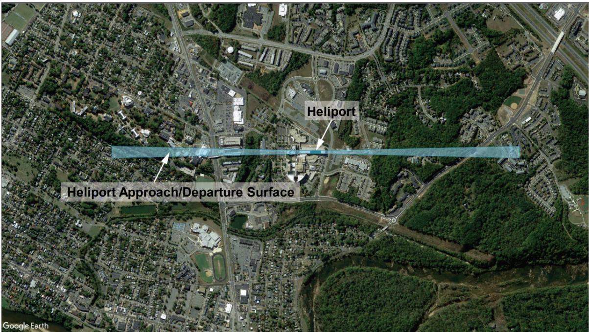
1.10.2 The preferred type of heliport location map using current web-based satellite imagery. Show the location of the heliport site and the approach/departure paths on the map. Point out the heliport site on this map with a red arrow. Indicate the latitude and longitude of the proposed heliport in North American Datum of 1983 (NAD-83) coordinates. See Figure 1-3.
Figure 1-1. FAA Form 7480-1, Notice for Construction, Alteration and Deactivation of Airports
| U.S. Depatment of Transportation OMBCONTROLNUMBER:2120-0036Federal Aviation Administration EXPIRATIONDATE:11/30/2022 | ||||||||||||
| NOTICE FOR CONSTRUCTION, ALTERATION AND DEACTIVATION OF AIRPORTS | ||||||||||||
| A. Airport Owner Check if this is also the Property Owner | B. Airport Manager (Complete if different than the Airport Owner) | |||||||||||
| 1.Name and Address Check if this is the Airport's Physical Address | 1.Name and Address Check if this is the Airport's Physical Address | |||||||||||
| 2.Phone | 3.Email | 2.Phone | 3.Email | |||||||||
| C. Purpose of Notification (Answer allquestions that apply) | D. Name, Location, Use and Type of Landing Area | |||||||||||
| 1.Construct orEstablish an: | AiportUtralight Fightpark□BallonportHeliport□Seaplane Base □Other | 1.Name of Landing Area | 2.Loc ID (for existing) | |||||||||
| 2.Construct, AlterorRealign a | □Runway□Helipad(s) □other□TaxiwayPublic UseAiports only) | 3.Associated City and State | 4.Distance from City(mm) | |||||||||
| 3.Change StatusFrom/To: | □VFR to IFR □IFR to VFR□Private Use to Public Use□Public Use to Other | 5.County(Physical Location) | 6.Direction from City | |||||||||
| 4.Change Traff cPattern | □DIRECTION:ALTITUDEChee Litalitueif nortannTurbo:std.nonstd. Prop:□stdnonstd.Helo. std nonstd. Otter Describein boxC6. | 7.Latitude。 1 = | 8. Longitude。 1 " | 9.Elevation | ||||||||
| 10.CurentUse: | PrivatePublic Private Use of Public Lands | |||||||||||
| 5.Deactivate | Airpot RWY □TWY | 11.Ownership | □PrivatePublic Military(Branch) | |||||||||
| 6. Description: | 12.Airport □Airport Ultralight Flihtpark BallonportHeliport(applicable elecAmbulanceLaw EnforcementType: Fire Protection) Seaplane Base□Other | |||||||||||
| E. Landing Area Data (List any Proposed, New or Unregistered Runways, Helipads etc.) | ||||||||||||
| 1.Airport, Seaplane Base or Ultralight Flightpark (use second pageif needed) | 2.Heliport, Balloonport or other Landing Area (use second pageif needed) | |||||||||||
| RWY ID | / | / | Helipad ID | |||||||||
| Lat. & Long. | Show on attachment(s) | Showon attachment(s) | Lat. & Long. | Show on atachment(s) | Show on attachment(s) | |||||||
| Surface Type | Surface Type | |||||||||||
| Length feet) | TLOF Dimensions | |||||||||||
| Width feet) | FATO Dimensions | |||||||||||
| Lighting (f any) | Lighting (if any) | |||||||||||
| Right Tratic (YN) | / | / | Ingress/Egress (Degrees) | |||||||||
| Elevation (AMSL) | Show on attachment(s) | Showon attachment(s) | Elevation (AMSL) | Showon attachment(s) | Show on attachment(s) | |||||||
| VFR or IFR | / | / | Elevated Height (AGL) | |||||||||
| F.Operational Dat | F. Operational Data (Indicate if the number provided is Actual or Estimated) | |||||||||||
| 1.Number of Based Aircraft | 2.Average Number of Monthly Landings | |||||||||||
| Present or Estim ated | Estimated in 5 Years | Present or Estimated | Estimated in 5 Years | |||||||||
| Single Engine | ||||||||||||
| Muli Engine | ||||||||||||
| Jet | ||||||||||||
| Helicopter | ||||||||||||
| Glider | ||||||||||||
| Military | ||||||||||||
| Utralight | ||||||||||||
| 3haie | ||||||||||||
| 4.Are IFRProcedures forthe Airport Anticipated?□Yes□No.IfYes,within _years | ||||||||||||
| G.CERTereycerify hatalof theabvestateertsae earetreancopleteheestofy wee. | ||||||||||||
| 1.Name,tite of person fing this notice (ype or prit) | 2.Signature (inink) | |||||||||||
| 3.Date 4.Phone 5.Email | ||||||||||||
FAAForm7480-1(7/20)SUPERSEDES PREVIOUSEDITION
See online FAA Form 7480-1.
Figure 1-2. Example of a Heliport Layout Plan
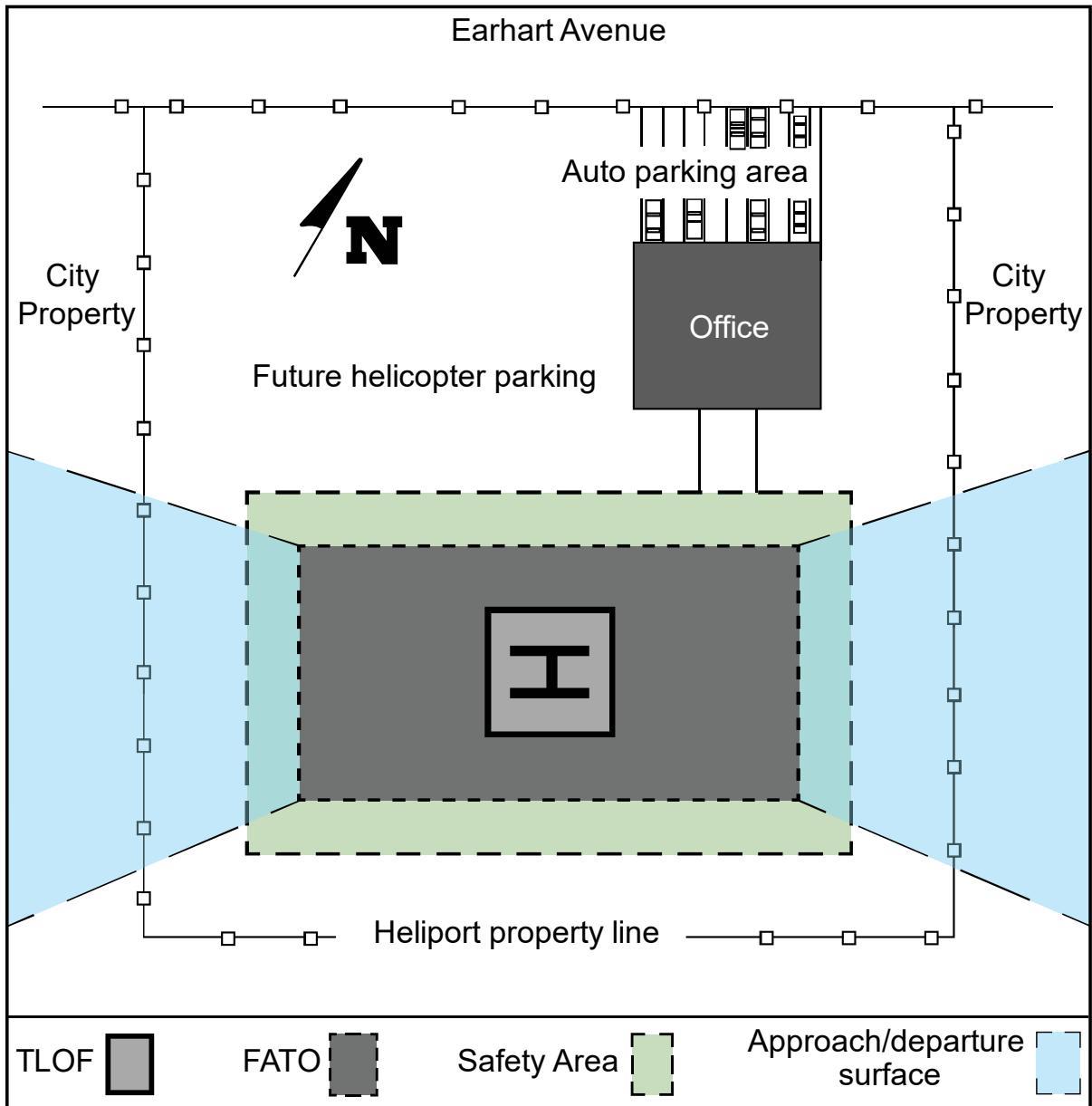
Draw heliport layout plan to scale with key dimensions and locations, including:
a. TLOF and FATO size
b. Safety area dimensions
c. Distances from the safety area perimeter to property boundaries, buildings, etc.
d. Site furnishings (bollards, signs, benches, and other site accessories)
See Chapter 2 for guidance on heliport facility sizes and shapes.
Figure 1-3. Example of a Heliport Location Map
1.10.3 The FAA Role.
The FAA will conduct an aeronautical study of the proposed heliport under § 157.7, FAA Determinations. Part (a) of this section of the regulation states:
“The FAA will conduct an aeronautical study of an airport proposal and, after consultations with interested persons, as appropriate, issue a determination to the proponent and advise those concerned of the FAA determination. The FAA will consider matters such as the effects the proposed action would have on existing or contemplated traffic patterns of neighboring airports; the effects the proposed action would have on the existing airspace structure and projected programs of the FAA; and the effects that existing or proposed manmade objects (on file with the FAA) and natural objects within the affected area would have on the airport proposal. While determinations consider the effects of the proposed action on the safe and efficient use of airspace by aircraft and the safety of persons and property on the ground, the determinations are only advisory. Except for an objectionable determination, each determination will contain a determinationvoid date to facilitate efficient planning of the use of the navigable airspace. A determination does not relieve the proponent of responsibility for compliance with any local law, ordinance or regulation, or state or other federal regulation. Aeronautical studies and determinations will not consider environmental or land use compatibility impacts.”
1.10.4 Penalty for Failure to Provide Notice.
Persons who fail to give notice are subject to civil penalty under Title 49 United States Code 46301, Civil Penalties, of not more than $25,000 (or $1,100 if the person is an individual or small business concern).
1.10.5 Notice Exemptions.
Section 157.1, Applicability, exempts sites meeting one of the conditions below from the requirement to submit notice. These exemptions do not negate a notice or formal approval requirement prescribed by state law or local ordinance. For the purposes of applying the Part 157 exemption criteria cited in (2) and (3) below, a landing and associated takeoff is considered one operation. Section 157.1 projects are:
[A heliport] subject to conditions of a federal agreement that requires an approved current heliport layout plan to be on file with the FAA, or
[A heliport] at which flight operations will be conducted under visual flight rules (VFR) and which is used or intended to be used for a period of less than 30 consecutive days with no more than ten operations per day.
The intermittent use of a site that is not an established airport, that is used or intended to be used for less than one year, and at which flight operations will be conducted only under VFR. For this part, “intermittent use of a site” means:
a. the site is used or is intended to be used for no more than three days in any one week, and
b. no more than ten operations will be conducted in any one day at that site.
1.11 Hazards to Air Navigation.
Part 77 establishes requirements for notification to the FAA of objects that may affect navigable airspace. See Figure 1-4 for examples of development requiring notice to the FAA.
Part 77 sets standards for determining obstructions to navigable airspace and provides for aeronautical studies of such obstructions to determine their effect on the safe and efficient use of airspace. Part 77 applies only to the following:
public heliports and public airports;
airports operated by a federal agency or the Department of Defense (DoD); and
private airports and heliports with at least one FAA-approved instrument approach procedure.
1.11.1 FAA Studies.
1.11.1.1 Part 77.
Part 77 defines objects that are obstructions to surfaces. Presume these objects to be hazards to air navigation unless an FAA study determines otherwise. The FAA conducts aeronautical studies to determine the
physical and electromagnetic effect on the use of navigable airspace, air navigational facilities, public airports and heliports, and private airports and heliports with at least one FAA-approved instrument approach procedure. The FAA encourages public agencies to enact zoning ordinances to prevent man-made features from becoming hazards to navigation.
1.11.1.2 Part 157.
FAA aeronautical studies performed under Part 157 establish standards and notification requirements for anyone proposing to construct, alter, or deactivate a civil or joint-use (civil/military) airport or heliport. This regulation also addresses proposals that alter the status or use of airport or heliport facilities.
1.11.2 Mitigation of Hazards.
You may mitigate the adverse effect of an object presumed or determined to be a hazard by:
Removing the object.
Altering the object, for example, reducing its height.
Marking and/or lighting the object, provided an FAA aeronautical study has determined that the object would not be a hazard to air navigation if it were marked and/or lighted. Find guidance on marking and lighting objects in AC 70/7460-1, Obstruction Marking and Lighting.
1.11.3 Notification Requirements.
Part 77 requires persons proposing certain construction or alteration to give a 45-day notice to the FAA of their intent. Use FAA Form 7460-1, Notice of Proposed Construction or Alteration, to provide notification. See https://oeaaa.faa.gov/ for more information and to download FAA Form 7460-1. Alterations to an existing heliport requiring notification could include changes to heliport dimensions, approach and departure surfaces, heliport location, and heliport relocation to a different site.
Figure 1-4. Offsite Development Requiring Notice to the FAA
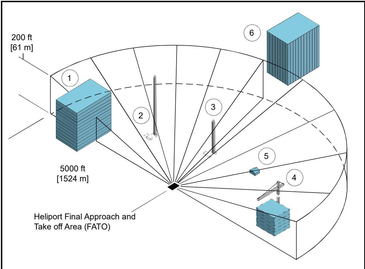
Notice under Part 77 is required for all public-use heliports or private-use heliports with at least one FAA-approved instrument approach procedure.
Offsite Development Examples for Figure 1-4:
① Building is less than 200 feet (ft) (61 meters (m)) in height, but top will penetrate the 25:1 surface (notice required by § 77.9).
② Antenna is over 200 ft (61 m) in height (notice is required by § 77.9(a)).
③ Antenna is less than 200 ft (61 m) in height and penetrates the 25:1 surface (notice is required by § 77.9(b)(3)).
④ Construction crane penetrates 25:1 surface (notice is required by § 77.9(b)(3)).
⑤ Building is less than 200 ft (61 m) in height and does not penetrate the 25:1 surface (notice is not required).
⑥ Building is more than 5,000 ft (1,524 m) from heliport (notice is required if building will be 200 ft (61 m) or more in height).
1.11.4 Heliport Development Plans.
Future public heliport development plans and feasibility studies on file with the FAA may influence the determinations resulting from Part 77 studies. Owners of public and private heliports with FAA-approved instrument approach procedures can ensure full consideration of future heliport development in Part 77 studies only when they file plans with the FAA. Ensure the coordinates and elevations of planned FATO(s),
approach/departure paths including their azimuths, and types of approaches for any new FATO or modification of an existing FATO are included in heliport plan data.
1.12 Federal Assistance.
The FAA administers a grant program that provides financial assistance to eligible sponsors to develop a public-use heliport. Information on federal aid program eligibility requirements is available from FAA Airports Regional and District Offices and on the FAA Airports website, www.faa.gov/airports.
1.13 Environmental Impact Analyses.
The National Environmental Policy Act (NEPA) of 1969 requires the FAA to consider potential environmental impacts prior to agency decision making, including, for example, the decision to fund or approve a project, plan, license, permit, certification, rulemaking, or operations specification. Actions that may warrant an environmental review are normally associated with federal grants or airport layout plan (ALP) approvals leading to the construction of a new heliport or significant expansion of an existing heliport.
1.13.1 Environmental Review Items.
An environmental review addresses noise, historic and cultural resources, wildlife, energy conservation, land usage, air quality, water quality, pollution prevention, light emissions, and other visual effects, and other public health and safety issues. The review evaluates the “no action” alternative and a reasonable range of feasible alternatives, including mitigation not included in the initial alternative. The review will also describe actions taken to ensure public involvement in the planning process. An opportunity for a public hearing may be required for the federally funded development of, or significant improvement to, an existing heliport.
1.13.2 Guidance.
FAA Order 1050.1, Polices and Procedures for Considering Environmental Impacts, FAA Order 5050.4, National Environmental Policy Act (NEPA) Implementing Instructions for Airport Projects, and other supplemental guidance from FAA Air Traffic and Flight Standards provide guidance on environmental impact analysis. Contact state and local governments, including metropolitan planning organizations and local transit agencies, directly, as they may also necessitate an environmental report. The procedures in AC 150/5020-1, Noise Control and Compatibility Planning for Airports, describe a means of assessing the noise impact. Contact the appropriate FAA Airports Regional or District Office for current information related to assessing the noise impact of heliports. Proponents of non-federally assisted heliports work with local governmental authorities concerning environmental issues.
1.14 Terminal Facilities Design Considerations.
A heliport terminal provides curbside access for passengers using private autos, taxicabs, and public transit vehicles. Public waiting areas need the usual amenities, and a counter for rental car services may be desirable. Design passenger auto parking areas to accommodate current requirements, with the ability to expand them to meet future requirements. Readily available public transportation may reduce the requirement for employee and service personnel auto parking spaces. Build attractive and functional heliport terminal buildings or sheltered waiting areas. Guidance on designing terminal facilities is provided in AC 150/5360-13, Airport Terminal Planning.
At PPR heliports, the number of people using the facility may be so small that there is no need for a terminal building, and minimal needs for other facilities and amenities.
1.14.1 Security – TRANSPORT Heliports.
Unless screening was carried out at the helicopter passengers’ departure location, Transportation Security Administration regulations may require that a screening area and/or screening be provided before passengers enter the airport’s secured areas. If needed, provide multiple helicopter parking positions and/or locations in the terminal area to service helicopter passenger and/or cargo interconnecting needs. Find information about passenger screening at the Transportation Security Administration website (https://www.tsa.gov/public/).
1.15 Zoning for Compatible Land Use.
The FAA encourages all heliport operators to promote the adoption of the following zoning measures where state and local statutes permit to ensure the heliport will continue to be available and to protect the investment in the facility.
1.15.1 Zoning to Limit Building/Object Heights.
Find general guidance on drafting an ordinance that would limit building and object heights in AC 150/5190-4, A Model Zoning Ordinance to Limit Height of Objects Around Airports. Substitute the heliport surfaces for the airport surfaces described in the model ordinance.
1.15.2 Zoning for Compatible Land Use.
The FAA encourages public agencies to enact zoning ordinances to control the use of property within the HPZ and the approach/departure path environment, restricting activities to those that are compatible with helicopter operations. See paragraph 2.13.
1.15.3 Air Rights and Property Easements.
Use air rights and property easements as options to prevent the encroachment of obstacles near a heliport.
1.16 Access to Heliports by Individuals with Disabilities.
Congress has passed various laws concerning access to airports. Since heliports are a type of airport, these laws are similarly applicable. Find guidance in AC 150/5360-14, Access to Airports by Individuals with Disabilities.
1.17 State Role.
Many state departments of transportation, aeronautical commissions, or similar authorities require prior approval and, in some instances, a license for the establishment and operation of a heliport. Several states administer a financial assistance program like the federal program and are staffed to provide technical advice. Contact your respective state aeronautics commissions or departments for specifics on licensing and assistance programs. Contact information for state aviation agencies is available at https://www.faa.gov/airports/resources/state_aviation.
1.18 Local Role and Building Code.
Some communities have enacted zoning laws, building codes, fire regulations, etc., that can affect heliport establishment and operation. Most municipalities have a formal process such as a “Conditional Use Permit” in place for the establishment of a heliport. Check with your local Planning and Zoning Commission for details. Some have or are in the process of developing codes or ordinances regulating environmental issues such as noise and air pollution. A few localities have enacted specific rules governing the establishment of a heliport. Therefore, make early contact with officials or agencies representing the local zoning board, the fire, police, or sheriff's department, and elected personnel who represent the area where the heliport is to be located.
1.19 Related Referenced Material.
Find a list of associated publications and references in Appendix E.
CHAPTER 2. Heliport Design
2.1 General.
This chapter provides guidance on the design of heliports. There are three types of heliports. GENERAL AVIATION, TRANSPORT, and HOSPITAL. Figure 2-1, Figure 2-2, and Figure 2-3 show basic features of these three heliport types. See paragraph 1.8 for descriptions of the three heliport types. This chapter provides general heliport design guidance and also highlights any differences in design elements among the types of heliports.
2.2 Prior Permission Required (PPR) Facilities.
Unless required by federal law or regulation, the recommendations in this AC are not mandatory for PPR heliports. Recommendations for PPR heliports are provided due to the specific nature of these heliport facilities where the operator ensures that pilots are thoroughly familiar with the heliport, its procedures, and any facility limitations.
2.3 Design Approach.
The design standards in this chapter assume that there will never be more than one helicopter within the FATO and the associated safety area. A TLOF can be located within the FATO or outside the FATO, as described in paragraph 2.7.
2.4 Access by Individuals with Disabilities.
Various laws require heliports operated by public entities and those receiving federal financial assistance to meet accessibility requirements. See paragraph 1.16.
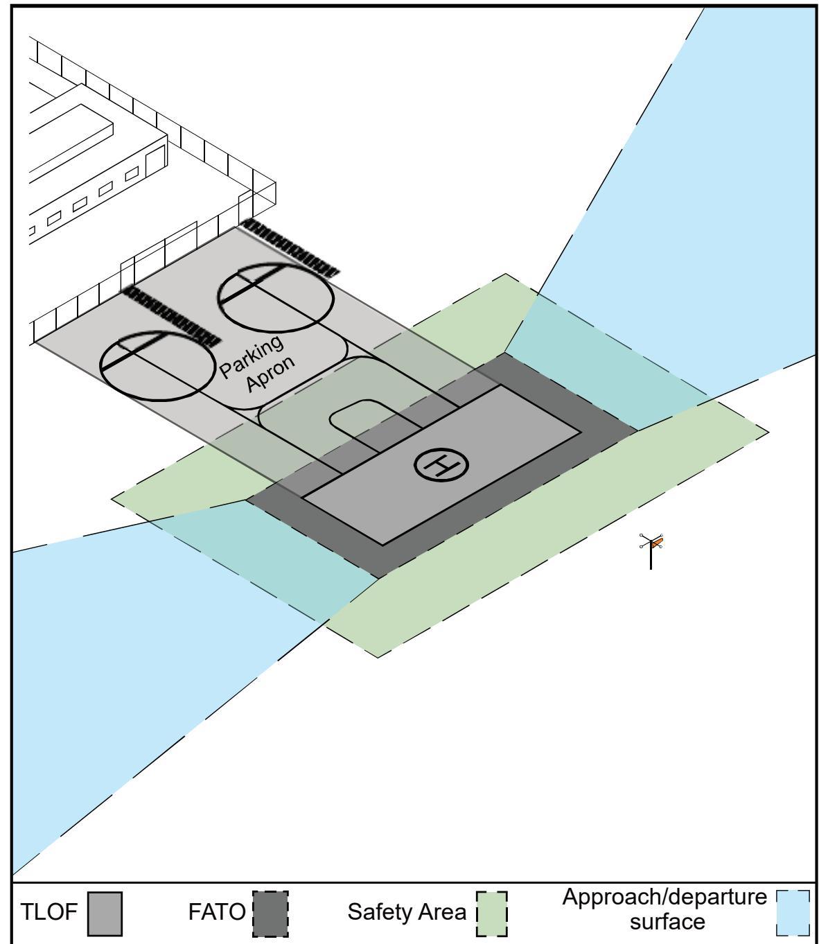
Figure 2-1. GENERAL AVIATION Heliport – Basic Features
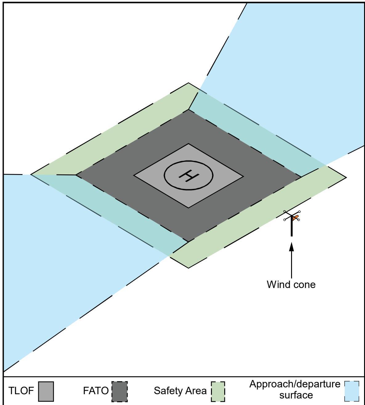
See Chapter 4 for guidance on heliport markings.
Locate the wind cone outside of the Safety Area. Ensure the wind cone and any security fencing or security barrier will not interfere with the approach/departure surface or transitional surface.
Figure 2-2. TRANSPORT Heliport – Basic Features
See Chapter 4 for guidance on heliport markings.
Locate the wind cone outside of the Safety Area. Ensure that the wind cone and any security fencing or security barrier will not interfere with the approach/departure surface or transitional surface.
Figure 2-3. HOSPITAL Heliport (Ground Level) – Basic Features
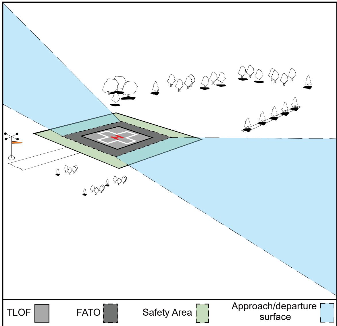
Locate the security fence and wind cone outside of the Safety Area. Ensure that the wind cone and any security fencing or security barrier will not interfere with the approach/departure surface or transitional surface.
See Chapter 4 for guidance on heliport markings.
2.5 Heliport Site Selection.
2.5.1 Long-term Planning.
The FAA encourages public agencies and others planning to develop a GENERAL AVIATION, TRANSPORT, or HOSPITAL heliport to consider the possible future need for instrument operations and facility expansion. Consider any current or future potential use by military helicopters that may be used in disaster relief efforts during planning for HOSPITAL heliports.
2.5.2 Property Requirements.
The property needed for GENERAL AVIATION and TRANSPORT heliports is dependent upon the volume and types of users, helicopter sizes, and the scope of amenities provided for each type of heliport facility. Property requirements for helicopter operators and for passenger amenities frequently exceed the property needed for “airside” purposes. The area needed for heliport or helipad operations may be as simple as a cleared area on the ground, a wind cone, and a clear approach/departure path for day heliport operations.
2.5.3 Turbulence.
Air flowing around and over buildings, stands of trees, terrain irregularities, etc., can create turbulence on ground-level and roof-top heliports that may affect helicopter operations. Assess the turbulence and airflow characteristics near, and across the surface of the FATO, and along the final section of the approach/departure path to determine if an air gap among the roof, roof parapet or supporting structure, and/or some other turbulence mitigating design measure is necessary. Perform this assessment where the FATO is located near the edge and top of a building or structure, or within the influence of turbulent wakes from other buildings or structures. The FAA’s Technical Report FAA/RD-84/25, Evaluating Wind Flow around Buildings on Heliport Placement, addresses the wind’s effect on helicopter operations. Take the following actions in selecting a site to minimize the effects of turbulence, as described in paragraphs below.
2.5.3.1 Ground-Level Heliports.
Proximity of buildings, trees, and other large objects to ground-level heliports can cause air turbulence and affect helicopter operations. Locate the landing and takeoff area away from such objects to minimize air turbulence near the FATO and the approach/departure paths.
2.5.3.2 Elevated Heliports.
Establishing a 6-foot (1.8 m) or more air gap on all sides above the roof level will generally minimize the turbulent effect of air flowing over the roof edge. If an air gap is included in the elevated heliport design, keep it free of objects that would obstruct the airflow. Where it is impractical to include an air gap or other turbulence mitigating design measures, operational limitations may be necessary under certain wind conditions.
2.5.4 Electromagnetic Effects.
Nearby electromagnetic devices, such as a large ventilator motor, elevator motor, magnetic resonance imaging machine (MRI), or other devices that consume large amounts of electricity may cause temporary abnormalities in the helicopter magnetic compass and interfere with other onboard navigational equipment. Buried rebar or other objects made of iron/steel below the heliport surface have also been shown to interfere with a helicopter’s navigation instruments.
Be alert to the location of any such devices with respect to a HOSPITAL heliport. A warning sign alerting pilots to the presence of an MRI is recommended. Take steps to inform pilots of the MRI locations or other electromagnetic equipment that consume large amounts of electricity. Heliports are recommended to include Heliport electromagnetic interference (EMI) hazard marking and signage to alert pilots to potential EMI impacts, as shown in Figure 2-4 and Figure 2-5. Locate the EMI hazard sign at ingress/egress points on the heliport for maximum visibility.
For additional information, see the FAA’s Technical Report FAA/RD-92/15, Potential Hazards of Magnetic Resonance Imagers to Emergency Medical Service Helicopter Services.
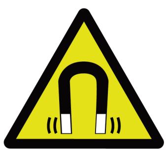
Figure 2-4. Heliport EMI Hazard Marking

Align the compass with magnetic north. Use arrows, as shown, to indicate the four cardinal headings (N, S, E, W) and four intercardinal headings (NE, SE, SW, and NW).
Use a minimum dimension of a 6-foot (1.8 m) outer diameter and a 4-foot (1.2 m) inner diameter for the compass circle.
Use blue paint for the compass circle and white paint for the inner portion of the compass. If necessary for visual contrast, use a one-foot white outline along the outer edge of the compass and arrows.
Figure 2-5. Heliport EMI Hazard Sign
CAUTION
Strong Magnetic Field
2.6 TLOF/FATO and Safety Area Relationships.
The relationship, minimum dimensions, and separation distances of the TLOF, FATO and safety area are shown in Figure 2-6 and Table 2-1. A heliport consists of the following:
A TLOF is typically located within a FATO but can be located outside of the FATO. See paragraph 2.7.1.
A safety area which surrounds the FATO.
Approach/departure surfaces to allow safe approaches to and departures from a heliport landing sites.
Figure 2-6. TLOF/FATO/Safety Area Relationships and Minimum Dimensions
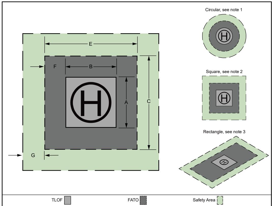
For a circular TLOF and FATO, dimensions A, B, C, and E refer to diameters.
For a square TLOF and FATO, all sides of the TLOF and FATO have equal length (e.g., dimension E = dimension C and dimension A = dimension B).
For a square TLOF with a rectangular FATO, dimension E ≠ dimension C.
Table 2-1. TLOF/FATO Minimum Dimensions 1
| Dim | Item | GA | TRANSPORT | HOSPITAL |
| A | TLOF Width | 0.83D | 0.83 D but not less than50 ft (15.2 m) | 0.83 D but not lessthan 40 ft (12.2 m) |
| B | TLOF Length | 0.83D | 0.83 D but not less than50 ft (15.2 m) | 0.83 D but not lessthan 40 ft (12.2 m) |
| C | FATO Length 2 | 1.50D | 1.66 D but not less than100 ft (30.5 m) | 1.50D |
| E | FATO Width | 1.50D | 1.66 D but not less than100 ft (30.5 m) | 1.50D |
| F | Separation between TLOFand FATO perimeters 3 | 0.34D | 0.34D | 0.34D |
| G | Safety Area Width | SeeTable 2-4 | 0.42 D but not less than30 ft (9.1 m) | See Table 2-4 |
See paragraph 2.7.2 for additional guidance.
See paragraph 2.8.5 for adjustments for heliport elevations above 1000′ MSL.
Confirm minimum separation between TLOF and FATO is maintained when the TLOF dimensions are adjusted.
2.7 Touchdown and Liftoff Area (TLOF).
2.7.1 TLOF Location.
TLOFs are located per the following guidelines:
Heliport TLOFs can be located at ground level, on elevated structures, and at rooftop level.
Every heliport will have at least one TLOF. For ground-based or water-based operations (but not rooftop operations), a TLOF can be located within the FATO or outside the FATO. This can be accomplished either over land or over water where the FATO is over the water and the TLOF is on land or is located on a water-based vessel. When the TLOF is located outside of the FATO, provide additional taxi route and/or hover taxi capability. See Figure 3-4.
When the TLOF is located within the FATO, the TLOF is centered within the FATO and along the major axis of the FATO, centered within the load-bearing area (LBA) and designed for dynamic loads.
As an option, TLOFs can be co-located with heliport parking positions outside of the FATO, as shown in Figure 3-4. These TLOFs are designed for static loadbearing. For TLOFs located outside of a FATO, ensure that there are no buildings or other obstacles in the vicinity of the TLOF that could cause turbulence or difficulties with helicopter maneuvering in crosswind conditions.
At a PPR heliport rooftop or other PPR elevated facility, where the entire FATO is not load-bearing, locating the TLOF in an LBA that is as large as possible may provide some operational advantages. Locate the TLOF in the center of the LBA in this case.
2.7.2 TLOF Size and Shape.
The TLOF size is a function of the heliport type and controlling dimension D of the design helicopter. A rectangular TLOF may provide the pilot with better alignment cues than a circular shape, but a circular TLOF may be more recognizable in an urban environment. Increasing the TLOF and the size of the LBA centered on the TLOF may provide enhanced safety and operational advantages. See Figure 2-6 and Table 2-1.
2.7.2.1 TLOF Size.
The size of the TLOF is shown in Table 2-1. Design considerations include:
For elevated public GENERAL AVIATION heliport and elevated HOSPITAL heliports, if the FATO is not load-bearing, increase the minimum width, length, or diameter of the TLOF to the D of the design helicopter.
At PPR facilities, if only a portion of the TLOF is paved, design the TLOF so the minimum length and width of this paved portion is not less than twice the maximum dimension (length or width) of the
undercarriage of the design helicopter. Locate the center of the TLOF in the center of this paved portion.
For HOSPITAL heliports, the minimum TLOF size is 40 ft × 40 ft (12.2 m × 12.2 m).
At PPR rooftop or elevated facilities, locate the center of the LBA of the TLOF in the center of the FATO when the TLOF is located inside and in the center of the FATO. Design the minimum dimension of the TLOF to be at least the smaller of 0.83 D and twice the maximum dimension (length or width) of the undercarriage of the design helicopter when the following two conditions are:
a. the height of the TLOF surface above the adjacent ground or structure is no greater than 30 inches (0.8 m),
b. there is a solid adjacent ground or structure equal to the OL able to support 20 lbs/square (sq) ft (98 kg/sq m) live load.
Consider the specified facility requirements for heliports where helicopter flight manuals specify the minimum size required for operations.
2.7.2.2 TLOF Shape.
For GENERAL AVIATION and HOSPITAL heliports, TLOFs are generally square, rectangular, or circular; however, other shapes may be used.
For TRANSPORT heliports, the TLOF is generally square or rectangular.
2.7.3 TLOF Design Loads.
2.7.3.1 Static Loads.
Design and construct the TLOF and any load-bearing surfaces to support the weight of the design helicopter and any ground support vehicles, as a minimum. For design purposes, the design static load is equal to the design helicopter’s maximum takeoff weight applied through the total contact area of the wheels or skids. Consult with helicopter manufacturers to obtain the contact area for the specific helicopters of interest.
Loads are applied through the contact area of the tires for wheel-equipped helicopters or the contact area of the skid for skid-equipped helicopters. See Appendix C for helicopter weights, landing gear configurations, and helicopter dimensional data.
2.7.3.2 Dynamic Loads.
Design elevated TLOFs, and any TLOF supporting structure, to be capable of supporting the dynamic loads of the design helicopter. See paragraph 2.7.7.2. A dynamic load of 0.2 second or less duration may occur during a hard landing. For design purposes, assume dynamic loads at 150 percent of the takeoff weight of the design helicopter. When specific loading data is not available, assume 75 percent of the weight of the design helicopter is applied equally through the contact area of the rear two wheels (or the pair of rear wheels of a dual-wheel configuration) of a wheel-equipped helicopter. For a skid-equipped helicopter, assume 75 percent of the weight of the design helicopter is applied equally through the aft contact areas of the two skids of a skid-equipped helicopter. (See Figure 2-14.) Contact manufacturers to obtain the aft contact area for specific helicopters of interest.
2.7.3.3 Rotor Loads.
Rotor downwash loads are approximately equal to the weight of the helicopter distributed uniformly over the disk area of the rotor. Rotor downwash loads are generally less than the loads specified in building codes for snow, rain, or wind loads typically used in structural design calculations.
2.7.4 Ground-level TLOF Pavement and Surface Characteristics.
General surface characteristics and pavement guidelines include:
Provide either a paved or aggregate-turf surface for the TLOF (see AC 150/5370- 10, Standard Specifications for Construction of Airports, Items P-217, Aggregate-Turf Pavement, and P-501, Cement Concrete Pavement).
Use Portland cement concrete (PCC) when feasible for ground-level facilities. An asphalt surface is less desirable for heliports as it may rut under the wheels or skids of a parked helicopter. This has been a factor in some rollover accidents. In addition, sections of asphalt have also been known to adhere to a helicopter’s skids only to fall off after takeoff creating a hazard to vehicles, buildings, and persons on the ground.
Use a roughened (broomed) pavement finish to provide a skid-resistant surface for helicopters and non-slippery footing for people.
Design the paved portion to dynamic load bearing where only a portion of the TLOF is paved for PPR heliports. Design the adjacent ground or structure of the TLOF for the static loads of the design helicopter.
To avoid unstable risk factors such as dynamic rollovers, match the transition elevations between the paved and unpaved portions of the TLOF.
Provide a 10-foot-wide rapid runoff shoulder at a negative 3-5% grade.
2.7.5 Ground-level TLOF Gradients.
To ensure positive drainage of the entire TLOF area, design the TLOF to have a negative gradient between 0.5 percent and 2 percent for GENERAL AVIATION and HOSPITAL heliports. For TRANSPORT heliports, design the TLOF to have a longitudinal gradient between 0.5 and 1 percent and a transverse gradient between 0.5 and 1.5 percent. Grade the entire TLOF to provide positive drainage. In addition, slope grades away from ingress/egress areas and emergency exits. See Figure 2-7.
Figure 2-7. Heliport Gradients and Rapid Runoff Shoulder - Load-bearing FATOs
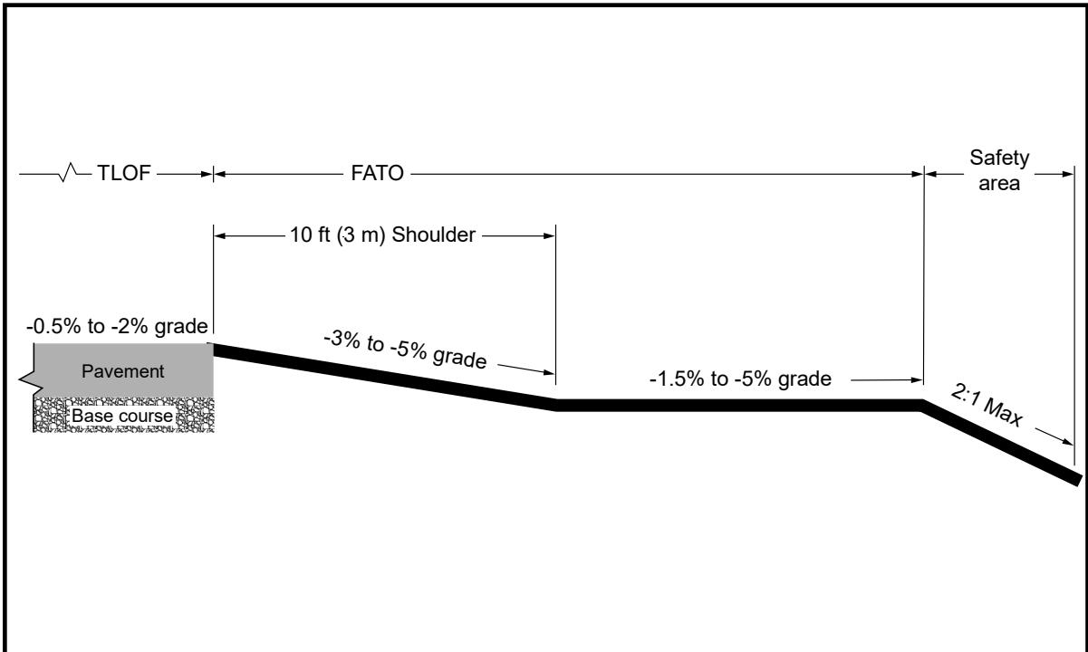
See paragraph 2.7.5 for specific gradient standards for HOSPITAL, GENERAL AVIATION, and TRANSPORT heliports.
The slope direction is based on the topography of the site.
Grade the TLOF, FATO, and safety area to provide positive drainage of the entire area for the TLOF, FATO, and safety area.
Stabilize FATO non-load-bearing surfaces.
2.7.6 Elongated TLOF and FATO.
2.7.6.1 Where space allows, an elongated TLOF and FATO can be provided to enhance safety and operational flexibility. This enhanced safety is particularly relevant during emergency landings as the elongated TLOF provides a longer TLOF area and longer FATO area for approach and landing. This configuration also provides enhanced obstruction clearance both longitudinally (along the approach/departure surfaces) and laterally (due to the longer transitional surfaces).
2.7.6.2 As an option, design an elongated TLOF with a landing position in the center and two takeoff positions, one at either end. If the TLOF is elongated, also provide an elongated FATO. See Figure 2-8 and Table 2-2 for the layout dimensions of an elongated FATO.
Figure 2-8. Optional Elongated TLOF and FATO with Two Takeoff Positions
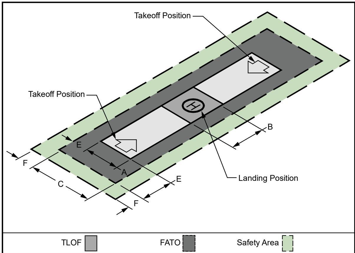
For a circular TLOF and FATO, dimensions A, B, C, and E refer to diameters.
Table 2-2. Minimum Dimensions for Elongated FATO with Two Takeoff Positions
| Dim | Item | GA | TRANSPORT | HOSPITAL |
| A | TLOF Width | 0.83D | 0.83 D but not less than50 ft (15.2 m) | 0.83 D but not less than40 ft (12.2 m) |
| B | TLOF/LandingPosition Length | 0.83D | 0.83 D but not less than50 ft (15.2 m) | 0.83 D but not less than40 ft (12.2 m) |
| C | FATO Width | 1.25 D | 1.66 D but not less than100 ft (30.5 m) | 1.25D |
| E | Separation Betweenthe TLOF and FATO | 0.34D | 0.34D | 0.34D |
| F | Safety Area Width | See Table 2-4 | 0.42 D but not less than50 ft (15.2 m) | See Table 2-4 |
2.7.7 Rooftop and Other Elevated TLOFs and FATOs.
2.7.7.1 Elevation and Configuration of Rooftop and other Elevated Heliports.
Table 2-3 provides design parameters related to elevation, obstacles, and edge restraints for rooftop and other elevated TLOFs and FATOs.
Table 2-3. TLOF Elevation and Configuration of Rooftop and other Elevated Heliports
| GA | TRANSPORT | HOSPITAL | |
| Elevation | TLOF elevation is abovethe elevation of theFATO | FATO and TLOFelevations are both abovethe elevation of theadjacent safety area | TLOF elevation is abovethe elevation of theFATO |
| Obstacles | Construct the TLOFabove the level of anyobstacle in the FATO andsafety area that cannot be|removed | Construct the FATOabove the level of anyobstacle in the safety area|that cannot be removed | Construct the TLOFabove the level of anyobstacle in the FATO andsafety area that cannot beremoved |
| Edgerestraints | N/A | N/A | Edge restraints ofminimal height (no higherthan 4 inches (102 mm))on ramps may projectabove the elevation of theedge of the TLOF |
See Figure 2-9 and Figure 2-10 for elevated heliport configurations.
Figure 2-9. Elevated Heliport: GENERAL AVIATION and HOSPITAL
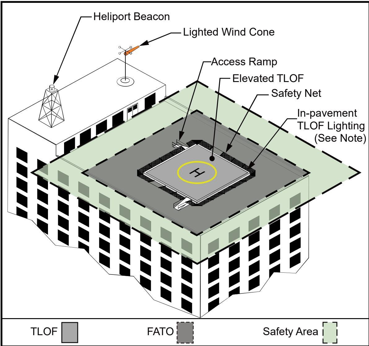
See Figure 4-9 for safety net and lighting details.
Figure 2-10. Elevated Heliport: TRANSPORT
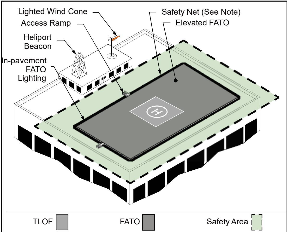
See Figure 4-9 for safety net and lighting details.
2.7.7.2 Elevated TLOF Design Loads.
Design elevated TLOFs, and any TLOF supporting structure, to be capable of supporting the dynamic loads of the design helicopter, described in paragraph 2.7.3.2 and Figure 2-14.
For TRANSPORT heliports, design both the TLOF and FATO, and any supporting structures, for the TLOF and FATO to be capable of supporting the dynamic loads of the design helicopter.
2.7.7.3 Elevated TLOF Surface Characteristics.
Construct rooftop and other elevated heliport TLOFs of aluminum, metal, or concrete (or other materials subject to local building codes).
Use a finish for TLOF surfaces that provides a skid-resistant surface for helicopters and non-slippery footing for people.
For TRANSPORT heliports, the surface characteristics described above apply to both the TLOF and FATO.
2.7.7.4 Access to Elevated TLOFs and Elevated FATOs.
Title 29 CFR Part 1926.34, Means of Egress, requires two separate access points for an elevated structure such as an elevated TLOF or FATO. Guidelines for access design include:
Design stairs in compliance with 29 CFR Part 1910.25, Stairways.
Design handrails described in this regulation to fold down or be removable to below the level of the TLOF or FATO so they will not be hazards during helicopter operations.
For HOSPITAL heliports, provide access to and from the TLOF via a ramp to provide for quick and easy transportation of a patient on a gurney. Build ramps in accordance with state and local requirements. Design the width of the ramp, and any turns in the ramp, to be wide enough to accommodate a gurney with a person walking on each side. Design straight segments of the ramp to be at least 6 feet (1.8 m) wide. Additional width may be required in the turns. Provide the ramp with a slip-resistant surface.
2.7.7.5 Elevated Heliport Design Considerations.
2.7.7.5.1 Obstructions.
Elevator penthouses, cooling towers, exhaust vents, fresh-air vents, and other elevated features can affect heliport operations. Establish control mechanisms to ensure obstruction hazards are not installed after the heliport is operational.
2.7.7.5.2 Air Quality.
Helicopter engine exhaust can affect building air quality if the heliport is too close to fresh air vents. When designing a building intended to support a helipad, locate fresh air vents to mitigate impacts on building air quality. When adding a heliport to an existing building, relocate fresh air vents, if necessary, or if relocation is not practical, install charcoal filters or a fresh air intake bypass louver system for heating, ventilation, and air conditioning (HVAC) systems or implement other measures as needed.
2.8 Final Approach and Takeoff Area (FATO).
A heliport has at least one FATO. The FATO typically contains a TLOF within its borders at which arriving helicopters terminate their approach and from which departing helicopters take off.
2.8.1 FATO Minimum Width, Length (or Diameter).
Design the FATO per the following guidelines:
Design the FATO and the safety area to be square or rectangular if the TLOF is square or rectangular, respectively.
Design the FATO and the safety area to be round if the TLOF is round.
The long axis of a rectangular FATO is aligned with the preferred flight path.
The minimum width and length of the FATO are shown in Table 2-1 for all three types of heliports.
See Figure 2-6 for a depiction of the relationship of the TLOF to the FATO and the safety area.
Design the distance between the TLOF, FATO, and safety area perimeters to be equidistant regardless of the shape of the TLOF.
For HOSPITAL heliports, locate the FATO to provide ready access to the hospital’s emergency room or to the intended destination for the patient.
At PPR heliports, the operator and heliport owner ensure all pilots using the facility are thoroughly knowledgeable with all facility limitations when the operator of a PPR heliport chooses not to provide additional FATO length.
2.8.2 FATO Load-bearing Capacity – Ground-level Heliports.
For both standard shaped FATOs and extended/elongated FATOs, the FATO outside the TLOF need not be load-bearing if the heliport operator marks the TLOF as load-bearing. This guidance applies to standard FATO shapes, or elongated or extended FATOs.
For GENERAL AVIATION and PPR heliports, if the heliport operator does not mark the TLOF and/or intends that the helicopter be able to land anywhere within the FATO, design the FATO outside the TLOF, and any FATO supporting structure (like the TLOF) to be capable of supporting the dynamic loads of the design helicopter, as described in paragraph 2.7.3.2.
2.8.3 FATO Ground-level Surface Characteristics.
Design the edge of the FATO abutting the TLOF to be at the same elevation as the TLOF. Treat the FATO to prevent loose stones and any other flying debris caused by rotor downwash, if the FATO is unpaved.
2.8.4 FATO Gradients.
2.8.4.1 Load-bearing FATO.
Design a load-bearing FATO to have a negative gradient between 0.5 percent and 5 percent away from the edge of the TLOF. Design a negative gradient of not more than 2 percent in any areas where a helicopter is expected to land. To ensure TLOF drainage, design gradients of rapid runoff shoulders to be between 3 and 5 percent. In addition, slope grades away from ingress/egress areas and emergency exits. See Figure 2-7.
2.8.4.2 Non-load-bearing FATO.
When the FATO is non-load-bearing and/or not intended for use by the helicopter, there are no specific requirements for the gradient of the
FATO. In this case, design the gradient to be negative 5 percent (-5%) or more to ensure adequate drainage away from the TLOF. However, stabilize non-load-bearing surfaces.
2.8.5 FATO Additional Length for Higher Elevations.
At elevations above 1000 feet (305 m) MSL, a longer FATO provides an increased safety margin and greater operational flexibility. For ground-level heliports, provide the additional FATO length required, as shown in Figure 2-11. Design the minimum distance between the TLOF perimeter and the FATO perimeter to be no less than 0.34 D of the design helicopter to provide an increased safety margin and greater operational flexibility.
For elevated heliports above 1000 feet (305 m) MSL, performance characteristics of helicopters using the facility may be considered in lieu of, or in conjunction with, an additional FATO length, in particular related to Hover-Out-of-Ground Effect (HOGE) capability.
Figure 2-11. Additional FATO Length for Heliports at Higher Elevations
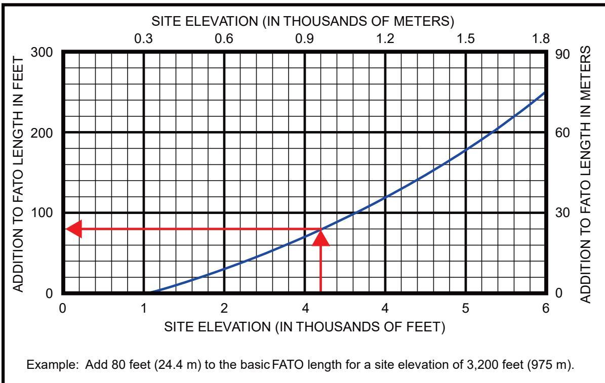
2.8.6 Rooftop and Other Elevated FATOs.
2.8.6.1 Design Loads.
Design elevated FATOs, and any FATO supporting structure, to be capable of supporting the dynamic loads of the design helicopter. See paragraph 2.7.3.2.
There are some helicopter performance benefits and increased operational flexibility if the FATO outside the TLOF is load-bearing. Design the FATO outside of the TLOF to be load-bearing or, as an option, increase the minimum width and length, or diameter of the TLOF, to the controlling dimension D of the design helicopter.
2.8.6.2 Elevation.
Elevate the FATO and TLOF above the level of any object in the safety area that cannot be removed.
2.8.6.3 FATO Extension into Clear Airspace.
As an option, where the FATO is non-load bearing, design the FATO outside the TLOF to extend into clear airspace for elevated heliports. Where space is available, portions of the FATO may share the rooftop for increased operational flexibility and helicopter performance benefits.
For elevated PPR heliports, consider the following:
a. As an option for elevated PPR heliports, design the FATO outside the TLOF and the safety area to extend into the clear airspace for elevated PPR heliports, if the heliport operator intends to mark the TLOF.
b. If the heliport operator does not mark the TLOF and/or intends that the helicopter be able to land anywhere within the FATO, design the FATO outside the TLOF and any FATO supporting structure (including the TLOF), to support the dynamic loads of the design helicopter.
c. As an option, increase the LBA length and width (or diameter, if a circle) without a corresponding increase in the size of the FATO.
FATOs can extend over water, as shown in Figure 2-12. In addition, FATOs can be located over water with associated TLOFs located on land. See Figure 3-4.
2.8.6.4 FATO Only Area.
A FATO can be established at a heliport for common-use approaches and departures only and would not include a TLOF within the FATO. In this case, one or more TLOFs would be located outside of the FATO, as described in paragraph 2.7 and shown in Figure 3-4.
2.8.6.5 Elevated Surface Characteristics.
Construct rooftop and other elevated heliport FATOs of metal, concrete, or other materials subject to local building codes. Provide the FATO surface with non-slippery footing for people.
2.8.6.6 Safety Net.
Construct safety nets, as described in paragraph 2.10.
2.8.6.7 Access to Elevated FATOs.
Provide access, as described in paragraph 2.7.7.4.
2.8.6.8 Fixed and Mobile Objects within the FATO.
The FATO design standards of this AC assume the TLOF and FATO are closed to other aircraft if a helicopter or other mobile object is within the FATO or the safety area. Remove all fixed objects projecting above the FATO elevation except for lighting fixtures, which may project a maximum of 2 inches (51 mm) and must be frangible. For ground-level heliports, remove all above-ground objects to the extent practicable.
2.8.6.9 FATO/FATO Separation.
Simultaneous landings or takeoffs may be authorized if the distance between the landing or takeoff points is at least 200 feet (61 m) and the courses to be flown do not conflict. Refer to surface markings to determine the 200-foot minimum.
2.9 Safety Area.
A safety area surrounds a FATO, as shown in Figure 2-1. The minimum safety area dimensions are provided in Table 2-1 for TRANSPORT heliports. For GENERAL AVIATION, HOSPITAL, and PPR heliports, the safety area width is the same on all sides and is a function of heliport marking scenarios, as shown in Table 2-4.
Table 2-4. Minimum VFR Safety Area Width as a Function of Heliport Markings GENERAL AVIATION, HOSPITAL, and PPR Heliports
| Scenario 1 | Scenario 2 | Scenario 3 | Scenario 4 | |
| TLOF perimeter marked | Yes | Yes | No | No |
| FATO perimeter marked | See Note | See Note | Yes | Yes |
| Standard "H" ' marking | Yes | No | Yes | No |
| Safety area widthGENERAL AVIATIONheliports | 0.28 D butnot less than20 ft (6.1 m) | 0.28 D butnot less than30 ft (9.1 m) | 0.50 D butnot less than20 ft (6.1 m) | 0.50 D butnot less than30 ft (9.1 m) |
| Safety area widthHOSPTIAL and PPRheliports | 0.28 D butnot less than10 ft (3 m) | 0.28 D butnot less than20 ft (6.1 m) | 0.50 D butnot less than20 ft (6.1 m) | 0.50D butnot less than30 ft (9.1 m) |
| Note: Scenarios 1 and 2 apply whether the FATO is not marked or not. Do not mark the FATO if (a) the FATO (or part of the FATO) is a non-load-bearing surface and/or (b) the TLOF iselevated above the level of a surrounding load-bearing area. | ||||
2.9.1 Fixed and Mobile Objects within the Safety Area.
The Safety Area design standards of this AC assume the TLOF and FATO are closed to other aircraft if a helicopter or other mobile object is within the FATO or the safety area. Remove all fixed objects within the Safety Area projecting above the FATO elevation except for lighting fixtures, which may project a maximum of 2 inches (51 mm) and must be frangible. For ground-level heliports, remove all above-ground objects to the extent practicable.
2.9.2 Safety Area Surface.
Guidelines on surface characteristics of safety areas include:
The safety area need not be load-bearing.
Design the safety area abutting the FATO at the same elevation as the FATO to avoid the risk of catching a helicopter skid or wheel.
Clear the safety area of flammable materials and treat the area to prevent loose stones and any other flying debris caused by rotor wash.
Safety areas can extend over water, as shown in Figure 2-12 and Figure 2-13.
2.9.3 Safety Area Gradients.
Design the surface of the safety area to be no steeper than a downward slope of 2:1 (2 units horizontal in 1 unit vertical). In addition, design the safety area elevation to be at or below the FATO edge elevation. See Figure 2-7.
Figure 2-12. Non-load-bearing FATO and Safety Area over Water: GENERAL AVIATION and HOSPITAL Heliports
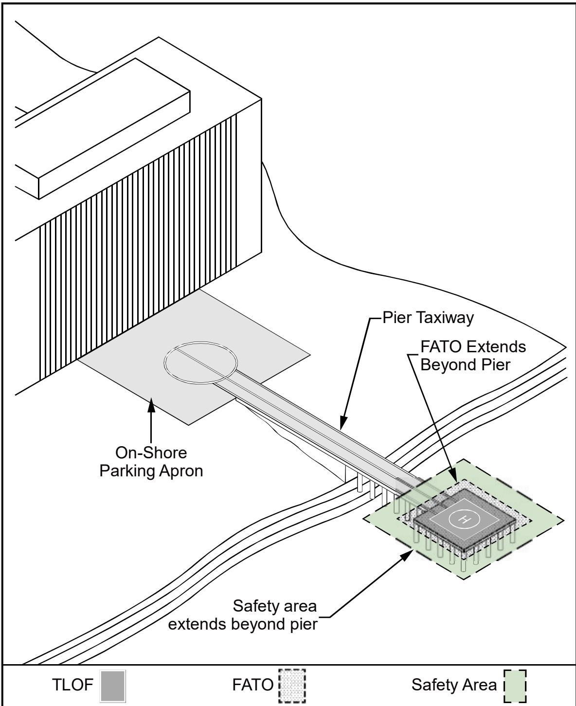
Figure 2-13. Non-load-bearing Safety Area over Water: TRANSPORT
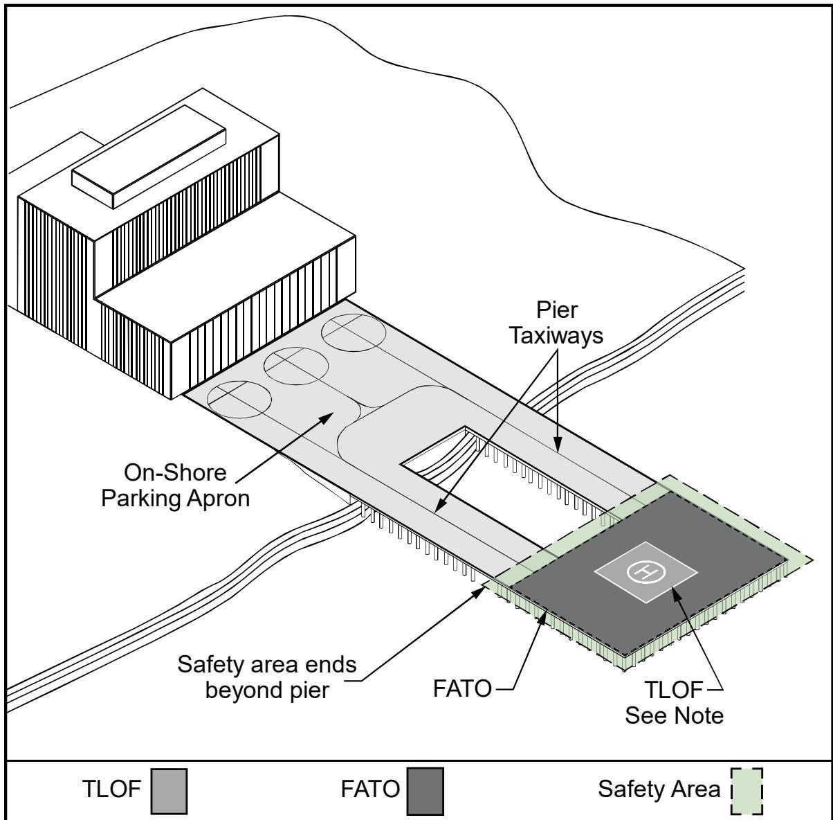
See paragraph 2.7 and Figure 3-4 for guidance on a TLOF located outside of the FATO.
2.10 Fall Protection and Safety Net Design.
Design heliport safety nets as follows:
Title 29 CFR Part 1910.23, Guarding Floor and Wall Openings and Holes, requires the provision of fall protection if the platform is elevated 4 feet (1.2 m) or more above its surroundings. The FAA recommends such protection for all platforms elevated 30 inches (0.8 m) or more.
Do not use permanent railings or fences since they would be safety hazards during helicopter operations.
Install a safety net meeting state and local regulations but not less than 5 feet (1.5 m) wide as an option.
Fasten both the inside and outside edges of the safety net to a solid structure.
Construct nets of materials that are resistant to environmental effects.
Table 2-5 describes the differences in safety net design for rooftop and other elevated heliports.
Table 2-5. Differences in Safety Net Design for Rooftop and Elevated Heliports
| GA | TRANSPORT | HOSPITAL | |
| Load | Design the safety net tohave a load carryingcapability of 25 1bs/sq ft(122 kg/sq m) | Design the safety net tohave a load carryingcapability of 50 1bs/sq ft(244 kg/sq m) | Design the safety net tohave a load carryingcapability of 25 lbs/sq ft(122 kg/sq m) |
| Elevation | Design the safety net tobe at or below theelevation of the TLOF | Design the safety net tobe at or below theelevation of the FATO | Design the safety net tobe at or below theelevation of the TLOF |
See Figure 4-9 for safety net characteristics.
2.11 Pavement Design and Soil Stabilization.
Pavements distribute a helicopter’s weight over a larger area of the subsurface, as well as provide a water-impervious, skid-resistant wearing surface. See Figure 2-14 and paragraph 2.7.3 for guidance on design loads.
Pave TLOFs, FATOs, taxiways, and parking aprons to improve their load carrying ability, minimize the erosive effects of rotor wash, and facilitate surface runoff.
PCC pavement is preferred over asphalt pavement for areas used for helicopter operations, wherever practical.
Stabilize turf areas on heliports subject to rotor downwash (including unpaved FATOs, unpaved taxiway shoulders, and other unpaved areas as needed), so these areas will not be subject to erosion or damage from rotor downwash due to helicopter operations.
In some instances, loads imposed by ground support vehicles may exceed those of the largest helicopter expected to use the facility and may require additional pavement thickness.
Thicker pavements may be needed to support heavier helicopters or where the quality of the subsurface soil is poor or questionable.
Find guidance on pavement design and soil stabilization in AC 150/5320-6, Airport Pavement Design and Evaluation, and AC 150/5370-10 at the FAA Airports website (https://www.faa.gov/airports).
Figure 2-14. Helicopter Landing Gear Loading: Gradients and Pavement
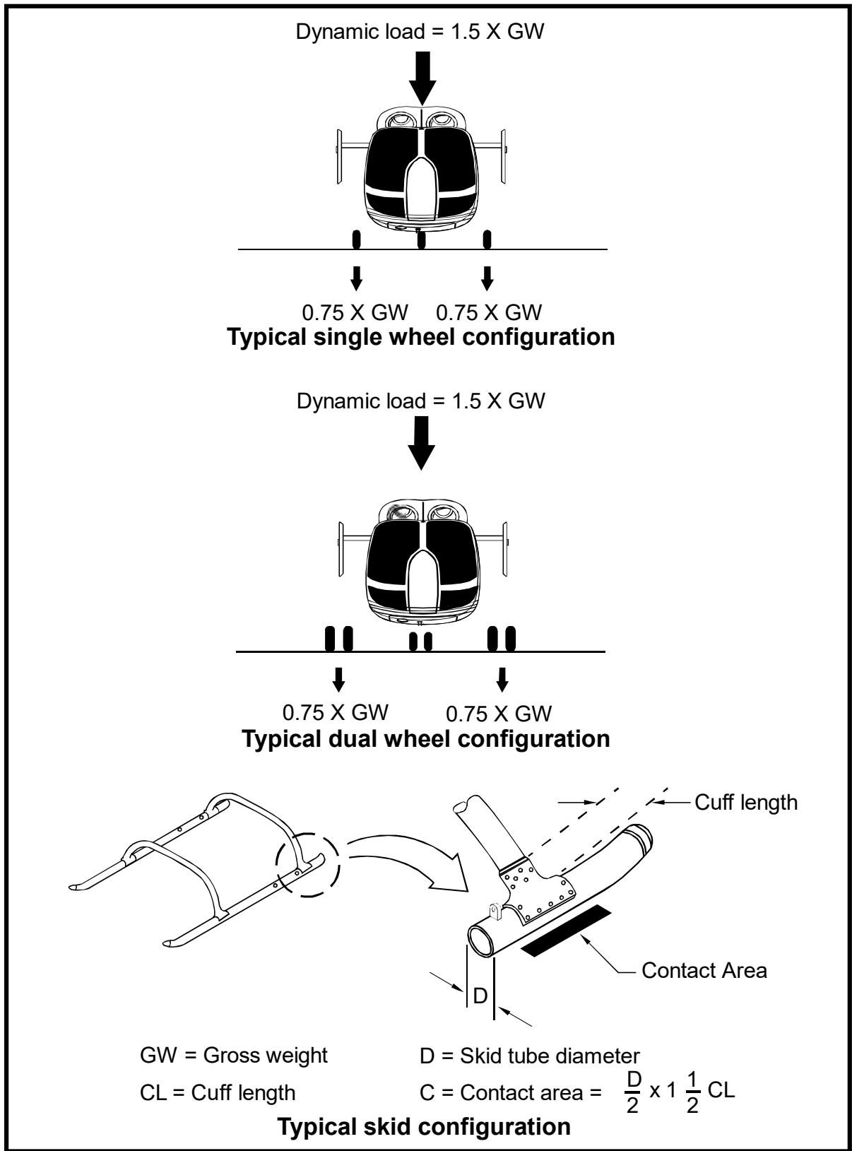
2.11.1 Soil Stabilization.
Use appropriate methods of soil stabilization to meet different site requirements. Consider helicopter weight, ground support vehicle weight, operational frequency, soil analysis, and climatic conditions in selecting the method(s) and extent of surface stabilization.
2.11.1.1 Turf.
A well-drained and well-established turf that presents a smooth, dense surface is usually the most cost-effective surface stabilization available. In some combinations of climates and weather conditions, turf surfaces can support the weight of many of the smaller helicopters for low frequency use by private and corporate operators during much of the year. Turf surfaces also provide reasonable protection against wind, rotor wash, or water erosion. Climatic and soil conditions dictate the appropriate grass species to use at the site. Find guidance on turf establishment in AC 150/5370-10.
2.11.1.2 Aggregate Turf.
Where heliports are located on soils that have poor load-carrying capabilities when wet, consider overcoming this deficiency by mixing selected granular materials into the upper 12 inches (0.3 m) of the soil. Suitable granular materials for this purpose are crushed stone, pit-run gravel, coarse sand, or oyster shells. Use a sufficient ratio of aggregate to soil to improve the stability of the soil yet retain the soil’s ability to support grass. For additional guidance, see Item 217 of AC 150/5370-10.
2.11.2 Formed Masonry Shapes and Other Materials.
Precast masonry shapes vary in size and shape from a brick paver to an open block. Lay pavers on a prepared bed to present a solid surface. Embed precast blocks in the soil with grass growing in the natural openings. Architectural catalogs identify different masonry shapes that are commercially available for this purpose. Other materials such as pre-manufactured concrete or newer materials may be used where applicable.
2.11.3 Pierced Metal Panels.
Lay perforated metal panels that may allow grass to grow through the openings on the ground to provide a hard surface for helicopter operations. Engineering catalogs identify commercially available panels.
2.12 VFR Approach/Departure Paths.
The approach/departure and transitional surfaces provide enough airspace clear of hazards to allow safe approaches to, and departures from, the FATO. Figure 2-15 and Figure 2-16 show these surfaces for straight-in and curved approaches, respectively. Note that VFR approach/departure sectored airspace can be used to provide increased approach/departure airspace and enhanced obstacle clearance surfaces for helicopter approaches and departures. Sectored airspace can provide helicopter pilots with greater flexibility and enhanced safety, particularly in areas with mountains or nearby obstructions (e.g., buildings), or heliports in areas with variable wind conditions.
Figure 2-15. VFR Heliport Approach/Departure and Transitional Surfaces
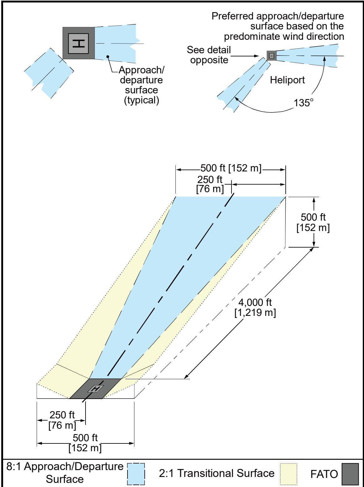
Figure 2-16. VFR Curved Approach/Departure and Transitional Surfaces – GENERAL AVIATION and TRANSPORT Heliports
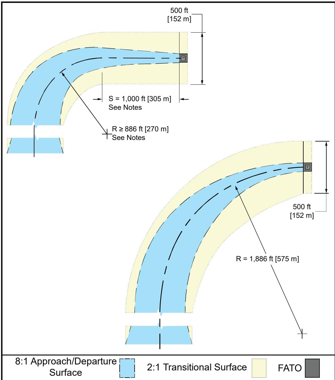
Use any combination of straight portions of one curved portion using the following formula: S + R ≥ 1,886 ft (575 m) and R ≥ 886 ft (270 m), where S is the length of the straight portion(s) and R is the radius of the turn. Note that any combination ≥ 1,886 ft (575 m) will work.
The minimum total length of the centerline of the straight and curved portion is 4,000 ft (1,219 m).
Helicopter takeoff performance may be reduced in a curve. Consider a straight portion along the takeoff climb surface prior to the start of the curve to allow for acceleration.
2.12.1 Number of Approach/Departure Paths.
Develop heliport approach/departure paths per the following guidelines:
Align preferred approach/departure paths with the predominant wind direction so downwind operations are avoided and crosswind operations are kept to a minimum.
To accomplish this, design a heliport to have several approach/departure paths or sector approach/departure paths. This ability is especially important for TRANSPORT heliports.
Base additional approach/departure paths on the assessment of the prevailing winds and surrounding obstructions. When wind data is not available, separate additional flight paths and the preferred flight path by at least (but not limited to) 135 degrees. See Figure 2-15.
A second flight path provides an additional safety margin and operational flexibility for variable wind conditions. If it is not feasible to provide complete coverage of wind conditions through multiple approach/departure paths, operational limitations may be necessary under certain wind conditions. See paragraph 1.9.1.
At a PPR heliport that has only one approach/departure path, the heliport operator ensures all pilots using the facility are thoroughly knowledgeable with the approach/departure path, and any other facility limitations specific to this PPR heliport.
2.12.2 VFR Approach/Departure and Transitional Surfaces.
Figure 2-15 illustrates the approach/departure surfaces and transitional surfaces. Develop these heliport surfaces per the following guidelines:
An approach/departure surface is centered on each approach/departure path. The approach/departure path starts at the outer edge of the FATO and slopes upward at 8:1 (8 units horizontal in 1 unit vertical) for 4,000 feet (1,219 m) where the width is 500 feet (152 m) at a height of 500 feet (152 m) above the heliport elevation.
The transitional surfaces start from the edges of the FATO parallel to the flight path centerline, and from the outer edges of the 8:1 approach/departure surface and extend outwards at a slope of 2:1 (2 units horizontal in 1 unit vertical) for 250 feet (76 m) from the centerline. The transitional surfaces extend longitudinally from the edge of the FATO to the far end of the approach/departure surface. The transitional surface does not apply to the FATO edge opposite the approach/departure surface. See Figure 2-15.
Clear the approach/departure and transitional surfaces of penetrations unless an FAA aeronautical study determines such penetrations not to be hazards. The FAA conducts such aeronautical studies only at public heliports, heliports operated by a federal agency or the DoD, and private heliports. Paragraph 1.11 provides additional information on hazards to air navigation.
At HOSPITAL and PPR heliports, consider implementation of lateral extensions as an option per the following guidelines:
a. Increase the width of the 8:1 approach/departure surface for a distance of 2,000 feet (610 m) by adding lateral extensions, as shown in Figure 2-17.
b. The lateral extensions on each side of the 8:1 approach/departure surface start at the width of the FATO and are increased so that at 2,000 feet (610 m) from the FATO they are 100 feet (30.5 m) wide.
c. Ensure that obstacles do not penetrate both Area A and Area B, unless the FAA determines that the penetration is not a hazard. Mark or light all such penetrations. See paragraph 1.11 for more information on hazard determinations.
Figure 2-17. VFR HOSPTIAL and PPR Heliport Optional Lateral Extensions of the 8:1 Approach/Departure Surface
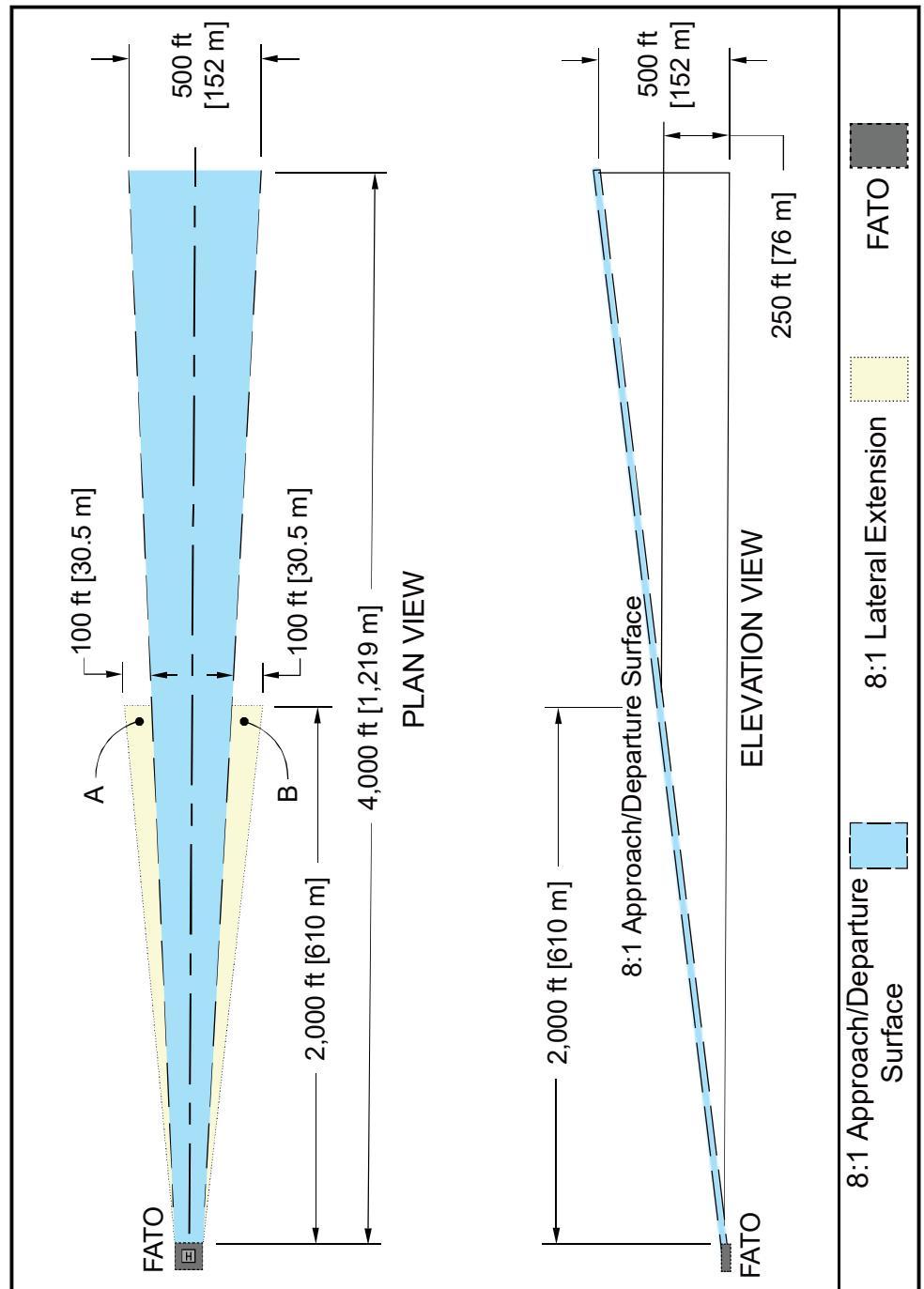
Allow penetration(s) of Area A or Area B lateral extensions but not both, provided that obstacles are marked or lighted and obstacles are not determined to be a hazard by the FAA.
2.12.3 Curved VFR Approach/Departure Paths.
2.12.3.1 Figure 2-16 shows curved approach/departure surfaces for GENERAL AVIATION and TRANSPORT heliports. Figure 2-18 shows curved approach/departure surfaces for HOSPITAL and PPR heliports.
2.12.3.2 Develop heliport curved VFR approach/departure paths per the following guidelines:
When including a curved portion in the approach/departure path, confirm the sum of the radius of the arc defining the centerline and the length of the straight portion originating at the FATO is not less than 1,886 feet (575 m).
Design the approach/departure path so the minimum radius of the curve is 886 feet (270 m) and that the curve follows a 1,000-foot (305 m) straight section.
Design the approach/departure path so the combined length of the centerline of the curved portion and the straight portion is 4,000 feet (1,219 m).
For HOSPITAL and PPR heliports, consider use of lateral extensions, as described in paragraph 2.12.2 subparagraph 4.
As an option, include one curve in VFR approach/departure paths.
As an option, design these paths to use the airspace above public lands, such as freeways, railroads, lakes, or rivers.
2.12.4 Flight Path Alignment Guidance.
As an option, use flight path alignment markings and/or flight path alignment lights where it is desirable and practicable to indicate approach and/or departure flight path direction(s). See Figure 2-19 and paragraph 4.8.
2.12.5 Periodic Review of Obstructions.
Heliport owners and operators should re-examine obstacles near approach/departure paths, at least annually, to prevent the encroachment of hazards. This re-examination includes an appraisal of tree growth near approach and departure paths. Paragraph 1.11 provides additional information on hazards to air navigation. Pay attention to obstacles that need to be marked or lighted. It may be helpful to maintain a list of the GPS coordinates and the top (highest) elevation of obstacles.
Figure 2-18. VFR HOSPITAL and PPR Heliport Optional Lateral Extension of the Curved 8:1 Approach/Departure Surface
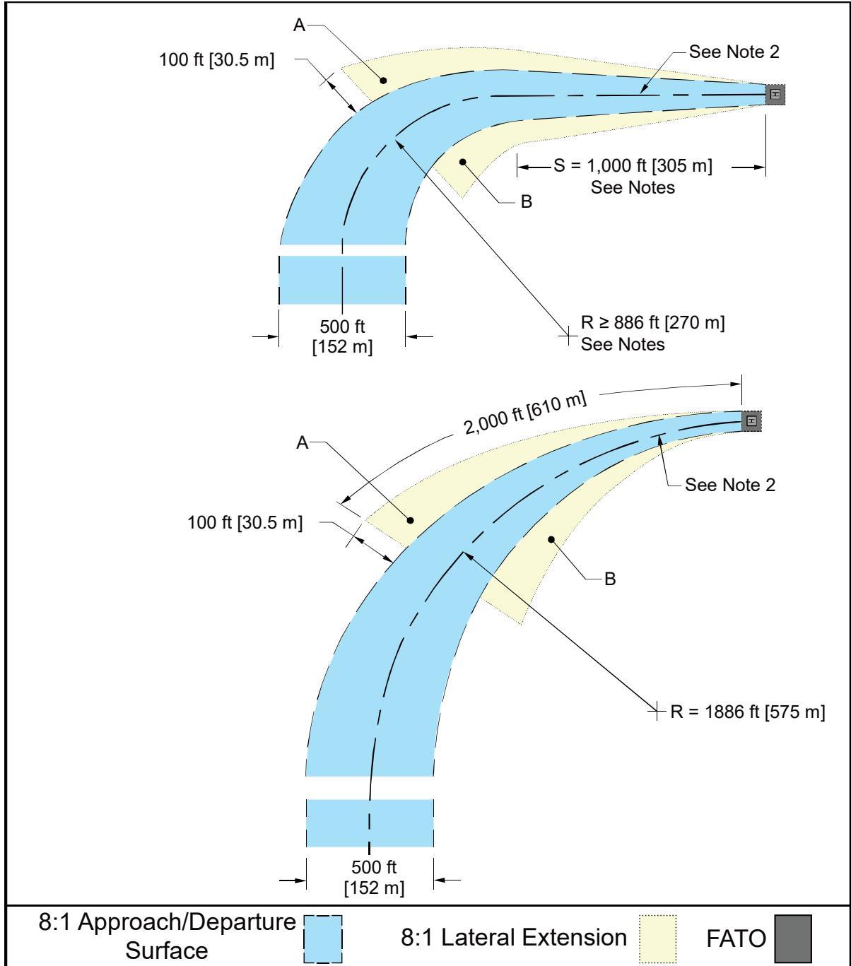
The approach surface may consist of one curved portion preceded and/or followed by one straight portion such that: S + R ≥ 1,886 ft (575 m) and R ≥ 886 ft (270 m), where S is the length of the straight portion(s) and R is the radius of the turn. Note that any combination ≥ 1,886 ft (575 m) will work.
The minimum total length of the centerline of the straight and curved portion is 4,000 ft (1,219 m).
Helicopter takeoff performance may be reduced in a curve. Consider a straight portion along the takeoff climb surface prior to the start of the curve to allow for acceleration.
Allow penetration(s) of Area A or Area B lateral extensions but not both, provided that obstacles are marked or lighted and obstacles are not determined to be a hazard by the FAA.
Figure 2-19. Flight Path Alignment Marking and Lights
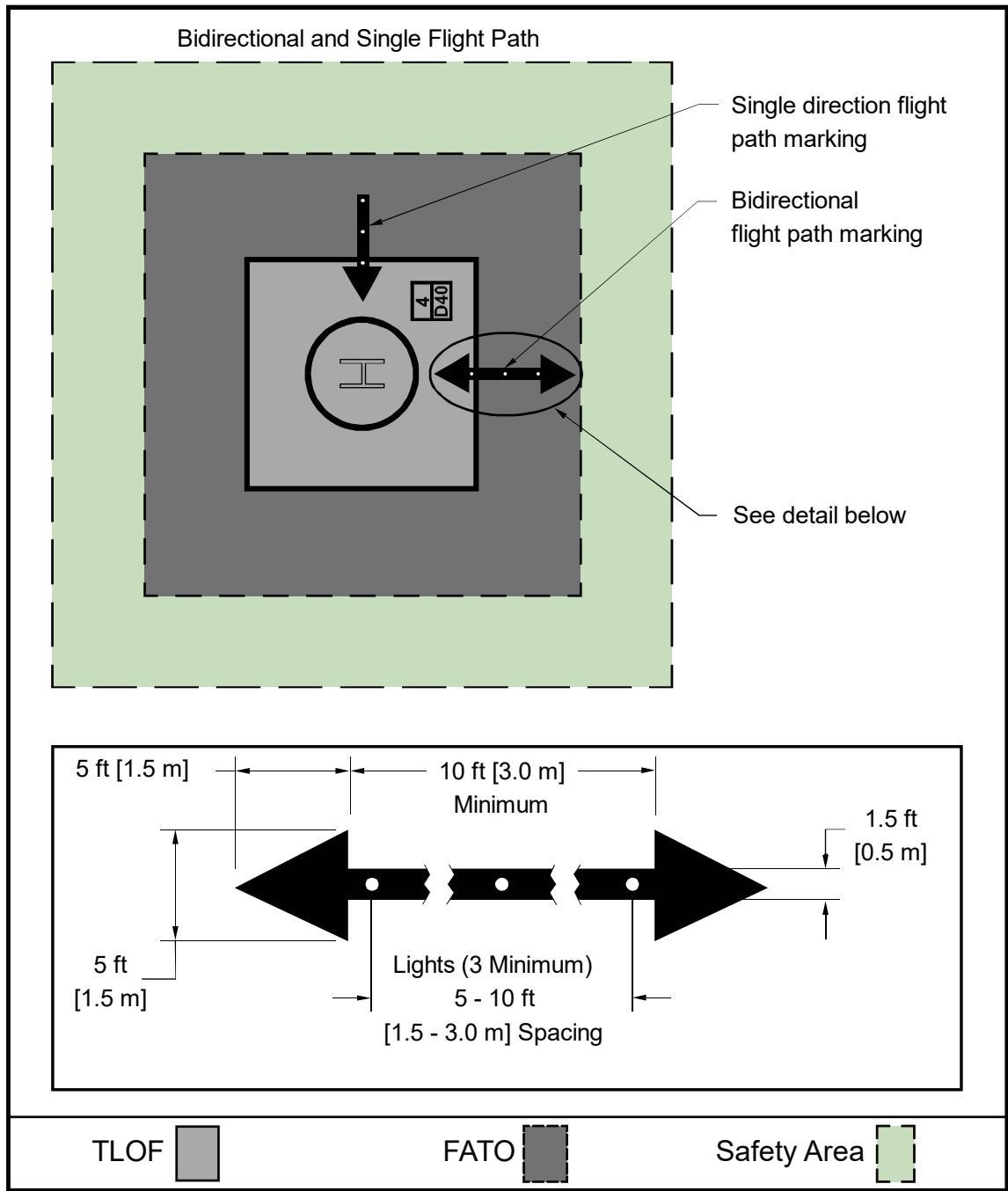
Arrowheads have constant dimensions.
If necessary, adjust stroke length to match length available. Minimum length = 10 ft (3 m).
Light type: omnidirectional green lights, Type L-860H or Type L-852H.
If necessary, locate the lights outside of the arrow.
In-pavement flight path alignment lighting is recommended.
See paragraph 4.8 for guidance on flight path alignment markings.
2.13 Heliport Protection Zone (HPZ).
The FAA recommends the establishment of an HPZ for each approach/departure surface. The HPZ is intended to enhance the protection of people and property on the ground. This is achieved through heliport owner control over the HPZ. In urban areas where space may be limited, the FAA encourages the heliport owner to control the maximum HPZ area practical. The FAA discourages residences and places of public assembly in an HPZ. (Churches, schools, hospitals, office buildings, parking lots, shopping centers, and other uses with similar concentrations of persons typify places of public assembly.) HPZ dimensions and recommendations include:
The HPZ is the area under the 8:1 approach/departure surface starting at the FATO perimeter and extending out for a distance of 280 feet (85 m) for GENERAL AVIATION and HOSPITAL heliports and a distance of 400 feet (122 m) for TRANSPORT heliports. See Figure 2-20.
The heliport owner should periodically evaluate and clear the HPZ of incompatible objects and activities.
Do not locate hazardous materials, including fuel, compressed oxygen, or other hazardous materials, within the HPZ.
2.14 Wind Cone.
2.14.1 Specification.
Install a wind cone conforming to AC 150/5345-27, Specification for Wind Cone Assemblies, to show the direction and magnitude of the wind. Use a color that provides the best possible contrast to its background.
2.14.2 Wind Cone Location.
Locate the wind cone to provide pilots with valid wind direction and speed information near the heliport under all wind conditions. See AC 150/5340-30, Design and Installation Details for Airport Visual Aids, for installation details. Follow these guidelines for wind cone location:
At many landing sites, there may be no single, ideal location for the wind cone. At other sites, it may not be possible to site a wind cone at the ideal location. In such cases, install more than one wind cone to provide pilots with all the wind information needed for safe operations.
Place the wind cone so pilots on the approach path can see it clearly when the helicopter is 500 feet (152 m) from the TLOF.
Place the wind cone so pilots can see it from the TLOF.
To avoid presenting an obstruction hazard, locate the wind cone(s) outside the safety area, and so it does not penetrate the approach/departure or transitional surfaces.
2.14.3 Wind Cone Lighting.
At a heliport intended for night operations, illuminate the wind cone, either internally or externally, to ensure it is clearly visible.
Figure 2-20. Heliport Protection Zone (HPZ)
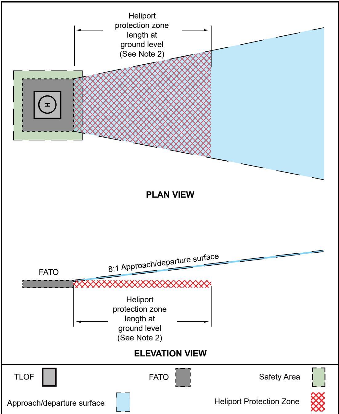
The approach surface starts at the edge of the FATO.
The length of the Heliport Protection Zone is 400 ft (122 m) for TRANSPORT heliports and 280 ft (85 m) for GENERAL AVIATION and HOSPITAL heliports.
See paragraph 2.12 for approach surface dimensions.
See paragraph 2.13 for specific HPZ recommendations.
CHAPTER 3. Heliport Taxiways, Taxi Routes, and Helicopter Parking
3.1 General.
This chapter provides guidance on heliport taxiways, taxi routes, and helicopter parking.
3.2 Taxiways and Taxi Routes.
Taxiways and taxi routes provide for the movement of helicopters from one part of a landing facility to another. They provide a connecting path between the FATO and a parking area. They also provide a maneuvering lane within the parking area. General guidance includes:
A taxi route includes the taxiway plus the appropriate clearances needed on both sides.
The configurations of taxiways are illustrated in Figure 3-1, Figure 3-2, and Figure 3-3 for both paved and unpaved taxiways.
At heliports with no parking or refueling area outside the TLOF(s), it is not necessary to provide a taxi route or taxiway.
3.3 Taxiway/Taxi Route Widths.
The dimensions of taxiways and taxi routes are a function of helicopter size, taxiway/taxi route marking, and type of taxi operations (ground taxi versus hover taxi). These dimensions are shown in Table 3-1. Normally, the requirement for hover taxi dictates the taxiway/taxi route widths. Consider the following guidelines when designing taxiway/taxi routes:
-
When the fleet comprises a combination of large ground taxiing helicopters and smaller air taxiing helicopters, the larger aircraft may dictate the taxiway/taxi route widths.
-
If wheel-equipped helicopters taxi with wheels not touching the surface, design the facility with hover taxiway widths rather than ground taxiway widths.
-
Where the visibility of the centerline marking cannot always be guaranteed, such as locations where snow or dust commonly obscure the centerline marking, and it is not practical to remove it, determine the minimum taxiway/taxi route dimensions as if there was no centerline marking.
-
Where the TLOF is located outside of the FATO, and aircraft access the TLOF after approaching and hovering at FATO, provide an air taxiway between the FATO and TLOF. See Figure 3-4.
Figure 3-1. Taxiway/Taxi Route Relationship – Paved Taxiway
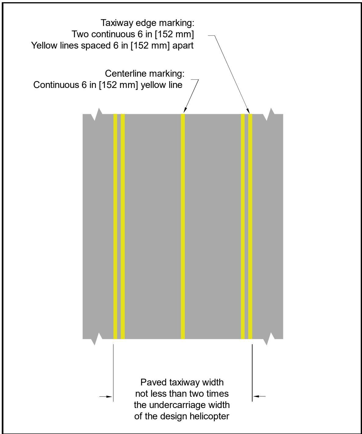
See Table 3-1 for taxiway/taxi route width.
Figure 3-2. Taxiway/Taxi Route Relationship – Unpaved Taxiway with Elevated Retroreflective Edge Markers
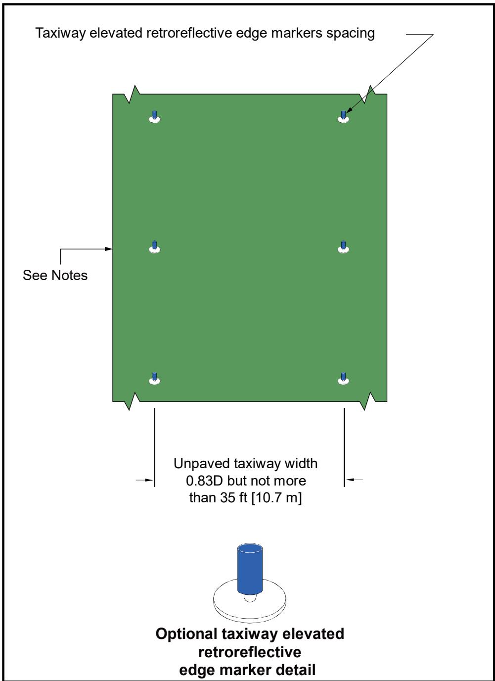
See Table 3-1 for taxiway/taxi route width.
Taxiway Marker Spacing: 15 ft (4.6 m) on straight segments.
Taxiway Marker Spacing: 10 ft (3.0 m) on curved segments.
Taxiway Marker Detail: 12-inch (0.3 m) minimum diameter disc at grade or not to exceed 3 inches (76 mm).
Taxiway Marker Detail: 4-inch (102 mm) diameter × 8-inch (203 mm) high maximum cylinder on a 2-inch (51 mm) support.
See AC 150/5345-39 for L-853 elevated retroreflective edge markers.
Figure 3-3. Taxiway/Taxi Route Relationship – Unpaved Taxiway with In-Pavement Retroreflective Edge Markers
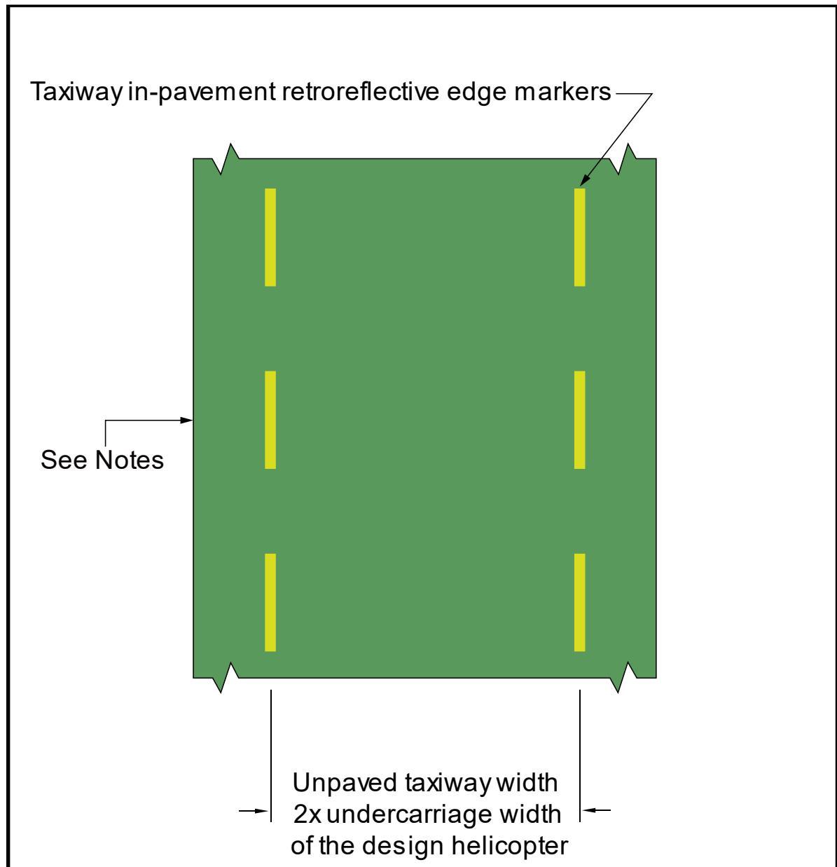
Taxiway in-pavement retroreflective edge markers 5 ft × 1 ft (1.5 m × 0.3 m).
Retroreflective edge marker spacing: 15 ft (4.6 m) on straight segments, 10 ft (3 m) on curved segments.
See Table 3-1 for taxiway/taxi route width.
Table 3-1. Taxiway/Taxi Route Dimensions – GENERAL AVIATION, TRANSPORT, and HOSPITAL Heliports
| Taxiway(TW)Type | MinimumWidth ofPaved Area | CenterlineMarkingType | TW EdgeMarkingType | Lateral Separation Between TWEdge Markings | Total TaxiRouteWidth |
| GroundTaxiway | 2 ×UCW | Painted | Painted | 2 ×UCW | 1.25D |
| Elevated | 0.83 D but not greater than 35 ft(10.7m) | ||||
| Unpaved butstabilized for|iground taxi | None | In-pavementi | 2×UCW | ||
| Elevated | 0.83 D but not greater than 35 ft(10.7 m) | ||||
| HoverTaxiway | 2×UCW | Painted | Painted | 2×UCW | 1.67D |
| |Unpaved | None | Elevated orIn-pavement|id | 0.83 D but not greater than 35 ft(10.7m) | ||
| D Controlling dimension of the design helicopterTW TaxiwayUCW Undercarriage Width of the design helicopter | |||||
Figure 3-4. Hover Taxi Area
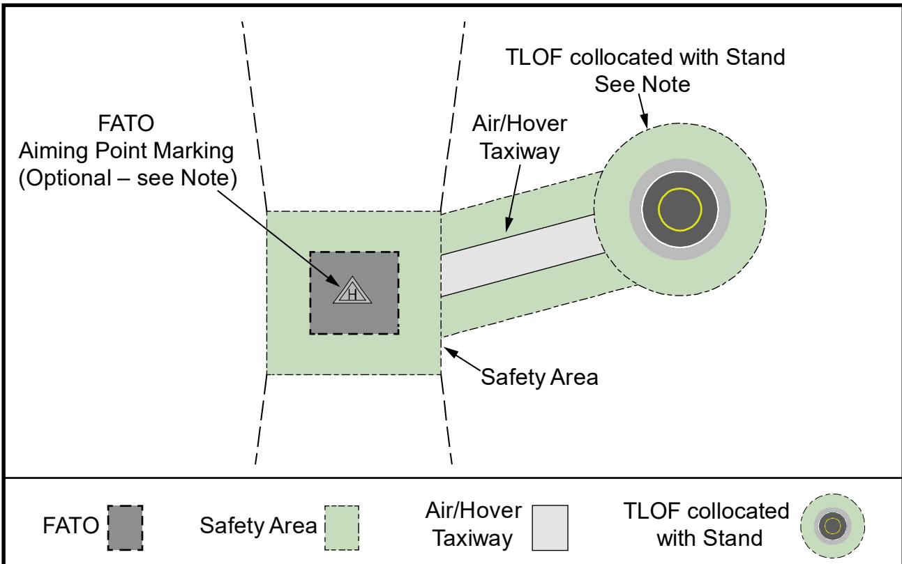
See paragraph 2.7 for guidance on a TLOF located outside of the FATO.
Configuration shown recommended by the International Federation of Helicopter Associations.
3.4 Taxiway Surfaces.
Guidelines for taxiway surfaces include:
-
For ground taxiways at TRANSPORT heliports, provide a Portland cement concrete or asphalt surface.
-
For ground taxiways at GENERAL AVIATION or HOSPITAL heliports, provide a Portland cement concrete, asphalt, or stabilized surface, such as turf, under the standards of Item P-217 of AC 150/5370-10.
-
For unpaved portions of taxiways and taxi routes, provide a turf cover or treat the surface in some way to prevent dirt and debris from being dispersed by a taxiing helicopter’s rotor down wash.
3.5 Taxiway and Taxi Route Gradients.
Design taxiway longitudinal gradients to not exceed 2 percent. Design transverse gradients to be between 0.5 percent and 2 percent.
3.6 Helicopter Parking.
If more than one helicopter at a time is expected at a heliport, design the facility with an area specifically designated for parking multiple helicopters. The size of this area depends on the number and size of specific helicopters to be accommodated.
It is not necessary that every parking position accommodate the design helicopter. Design the individual parking positions to accommodate the helicopter sizes and weights expected to use the parking position at the facility. However, use the design helicopter to determine the separation between parking positions and taxi routes. Use the largest helicopter to determine the separation between parking positions intended for helicopters of different sizes. Figure 3-5, Figure 3-6, and Figure 3-7 show typical helicopter parking layouts.
Design helicopter parking per the following guidelines:
-
Design the parking positions to support the static loads of the helicopter intended to use the parking area.
-
Design parking areas as one large, paved, apron or as individual, paved, parking positions.
-
Ground taxi turns of wheeled helicopters are significantly larger than a hover turn. Consider the turn radius of helicopters when designing taxi intersections and parking positions for wheeled helicopters.
-
Design heliport parking areas so helicopters will be parked in an orientation that keeps the “avoid areas” around the tail rotors clear of passenger walkways.
-
A TRANSPORT heliport may have paved areas for helicopter parking and separate paved areas for specific functions such as passenger boarding, maintenance, and parking of based and transient helicopters.
-
Design taxiway longitudinal gradients to not exceed 2 percent. Design transverse gradients to be between 0.5 percent and 2 percent.
Figure 3-5. Typical Parking Area Design – “Taxi-through” Parking Positions.
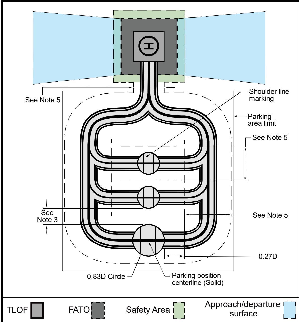
See Chapter 4 for guidance on heliport markings.
Design the parking positions so that the helicopters exit taxiing forward.
Minimum clearance between the arcs generated by the main rotor are:
a. for hover taxi operations, 0.28 D of the larger helicopter, but not less than 10 ft (3 m) b. for ground taxi operations, 10 ft (3 m)
For paved taxiways and parking positions, the taxiway centerline leads directly into the parking position centerline
See Table 3-1 for taxiway/taxi route width.
Figure 3-6. Typical Parking Area Design – “Turn-around” Parking Positions
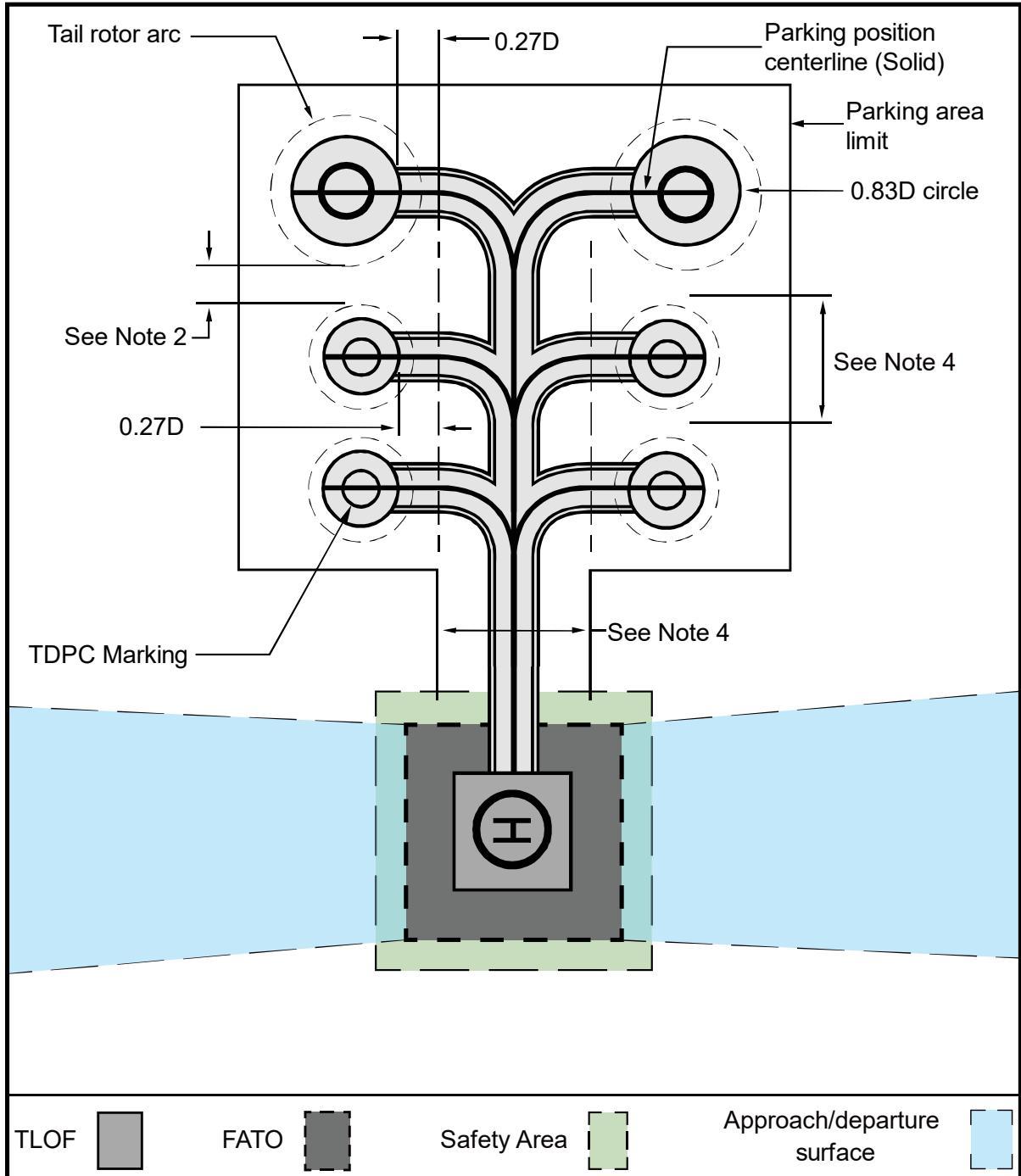
See Chapter 4 for guidance on heliport markings.
Minimum clearance between the tail rotor arcs generated by the main rotor arcs are: a. for hover taxi operations, 0.28 D of the larger helicopter, but not less than 10 ft (3 m) b. for ground taxi operations, 10 ft (3 m).
For paved taxiways and parking positions, the taxiway centerline leads directly into the parking position centerline.
See Table 3-1 for taxiway/taxi route width.
Figure 3-7. Typical Parking Area Design – “Back-out” Parking Positions
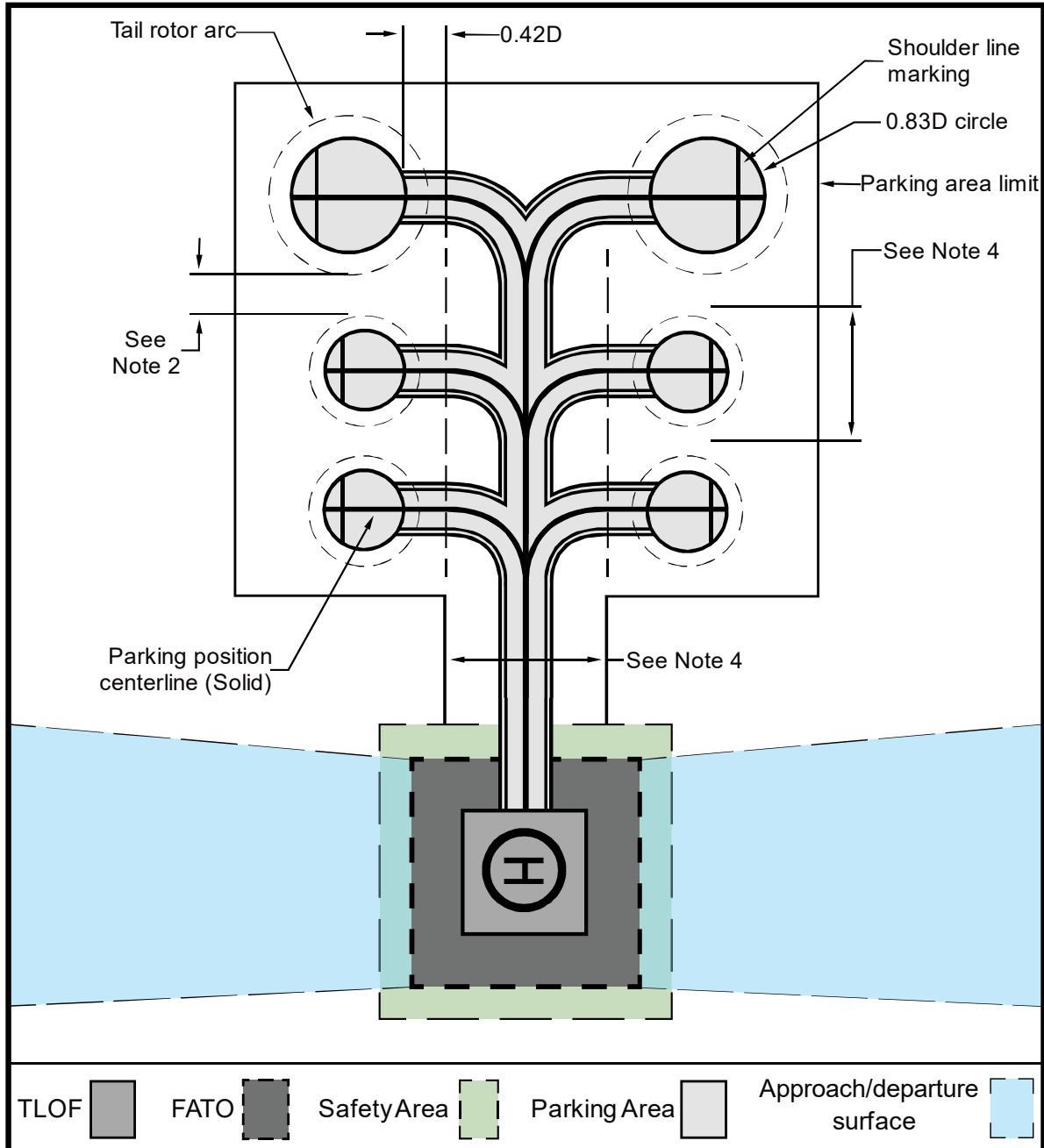
See Chapter 4 for guidance on heliport markings.
Minimum clearance between the tail rotor arcs generated by the main rotor arcs are:
a. for hover taxi operations, 0.28 D of the larger helicopter, but not less than 10 ft (3 m)
b. for ground taxi operations, 10 ft (3 m).
For paved taxiways and parking positions, the taxiway centerline leads directly into the parking position centerline.
See Table 3-1 for taxiway/taxi route width.
3.6.1 Location.
Guidelines for the location and clearances for helicopter parking include:
-
Locating aircraft parking areas outside of approach/departure surfaces. However, as an option, allow aircraft parking areas under the transitional surfaces.
-
Locating the parking position to provide a minimum distance between the tail rotor arc and any object, building, safety area, or other parking position for “turn-around” parking positions. This minimum distance is 10 feet (3 m) for ground taxi operations and the greater of 10 feet (3 m) or 0.28 D for hover taxi operations. See Figure 3-8.
-
Locating the parking position to provide a minimum distance between the main rotor circle and any object, building, safety area, or other parking position for “taxithrough” and “back-out” parking positions. The minimum distance is 10 feet (3 m) for ground taxi operations and the greater of 10 feet (3 m) or 0.28 D for hover taxi operations. See Figure 3-9.
Locating the parking position to provide a minimum distance between the main rotor circle and the edge of any taxi route. Design parking positions such that the helicopter taxis through, turns around, or backs out to depart. The minimum distance is 0.28 D for “taxi-through” and “turn-around” parking areas, and 0.42 D for “back-out” parking areas. See Figure 3-5, Figure 3-6, and Figure 3-7.
For TRANSPORT heliports, follow these additional helicopter parking guidelines:
a. Locate the parking position to provide a minimum distance between the tail rotor arc and the edge of any taxi route. The standard for this distance is 0.42 D but not less than 30 feet (9.1 m).
b. Do not design “back-out” parking positions at TRANSPORT heliports.
When possible, orient markings such that a pilot would be able to see incoming traffic from the parking position.
Figure 3-8. “Turn-around” Parking Position Marking
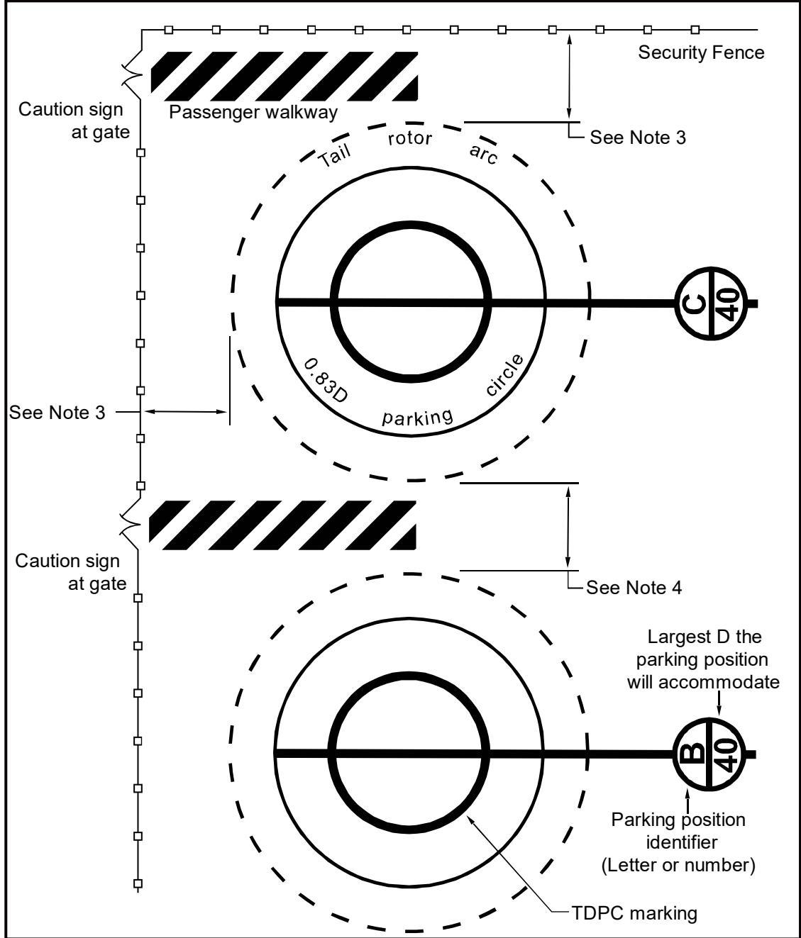
Base the design of these parking positions on the understanding that the helicopter may pivot about the mast prior to exiting the parking position.
This marking scheme is for paved areas only. For unpaved parking areas, all that is required is the 0.83 D marking.
Minimum clearance between the arcs generated by the main rotor arcs and fixed obstacles are: a. for hover taxi operations, 0.28 D of the larger helicopter, but not less than 10 ft (3 m) b. for ground taxi operations, 10 ft (3 m)
Minimum distance between tail rotor arcs is 0.28 D. If parking areas are different sizes, minimum distance is 0.28 D of the larger design helicopter.
See Chapter 4 for guidance on heliport markings.
Figure 3-9. “Taxi-through” and “Back-out” Parking Position Marking
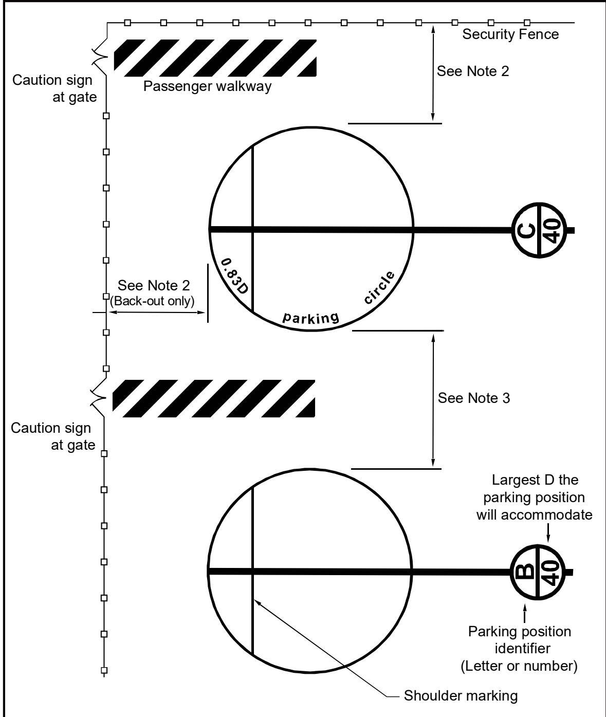
This marking scheme is for paved areas only. For unpaved parking areas, all that is required is the 0.83 D marking.
Minimum clearance between 0.83 D parking circle and fixed objects is:
a. for hover taxi operations, 0.28 D, but not less than 10 ft (3 m)
b. for ground taxi operations, 10 ft (3 m).
Minimum distance between 0.83 D parking circle is 0.28 D. If parking areas are different sizes, minimum distance is 0.28 D of the larger design helicopter.
See Chapter 4 for guidance on heliport markings.
3.7 Parking Position Sizes.
3.7.1 Parking position sizes are dependent upon the helicopter size. The clearance needed between parking positions is dependent upon the type of taxi operations (ground taxi or hover taxi) and the intended paths for maneuvering in and out of the parking position. The more demanding requirement will dictate what space is needed at a particular site.
3.7.2 The parking area requirements for skid-equipped helicopters will be the most demanding. The parking requirements for wheeled helicopters may be the most demanding when the largest helicopter is a very large, wheeled aircraft (for example, the S-61), and the skid-equipped helicopters are all much smaller. Design parking areas based on hover taxi operations rather than ground taxi operations if wheel-equipped helicopters taxi with wheels not touching the surface.
3.7.3 Guidelines for parking position size and layout include:
If all parking positions are the same size, design them to accommodate the largest helicopter that will park at the heliport.
“Taxi-through” parking positions are illustrated in Figure 3-5. When using this design exclusively for parking positions, the heliport owner and operator should inform users that “turn-around” departures from the parking position are not permitted.
“Turn-around” parking positions are illustrated in Figure 3-6 and apply to all heliport types.
“Back-out” parking positions can be used for GENERAL AVIATION and HOSPITAL heliports and are illustrated in Figure 3-7. When using this design for parking positions, design the adjacent taxiway to accommodate hover taxi operations so the width of the taxiway will be adequate to support “back-out” operations. (“Back-out” parking positions are not used at TRANSPORT heliports.)
When partially paving a parking area at GENERAL AVIATION or HOSPITAL heliports, design the smallest dimension of the paved parking pad to be a minimum of twice the maximum dimension (length or width, whichever is greater) of the undercarriage or the controlling dimension D, whichever is less, of the largest helicopter that will use the parking position. Place the parking pad in the center of the parking position circle.
When there is more than one parking position, as an option, design the facility with parking positions of various sizes with at least one position that will accommodate the largest helicopter that will park at the heliport. Design other parking positions to be smaller, for the size of the individual or range of individual helicopters parking at that position. Figure 3-10 and Figure 3-11 provides guidance on parking position identification, size, and weight limitations for “turn-around” and “taxi through and backout” parking positions, respectively.
Figure 3-10. Parking Position Identification, Size, and Weight Limitations – Paved Areas, Turn-Around Parking
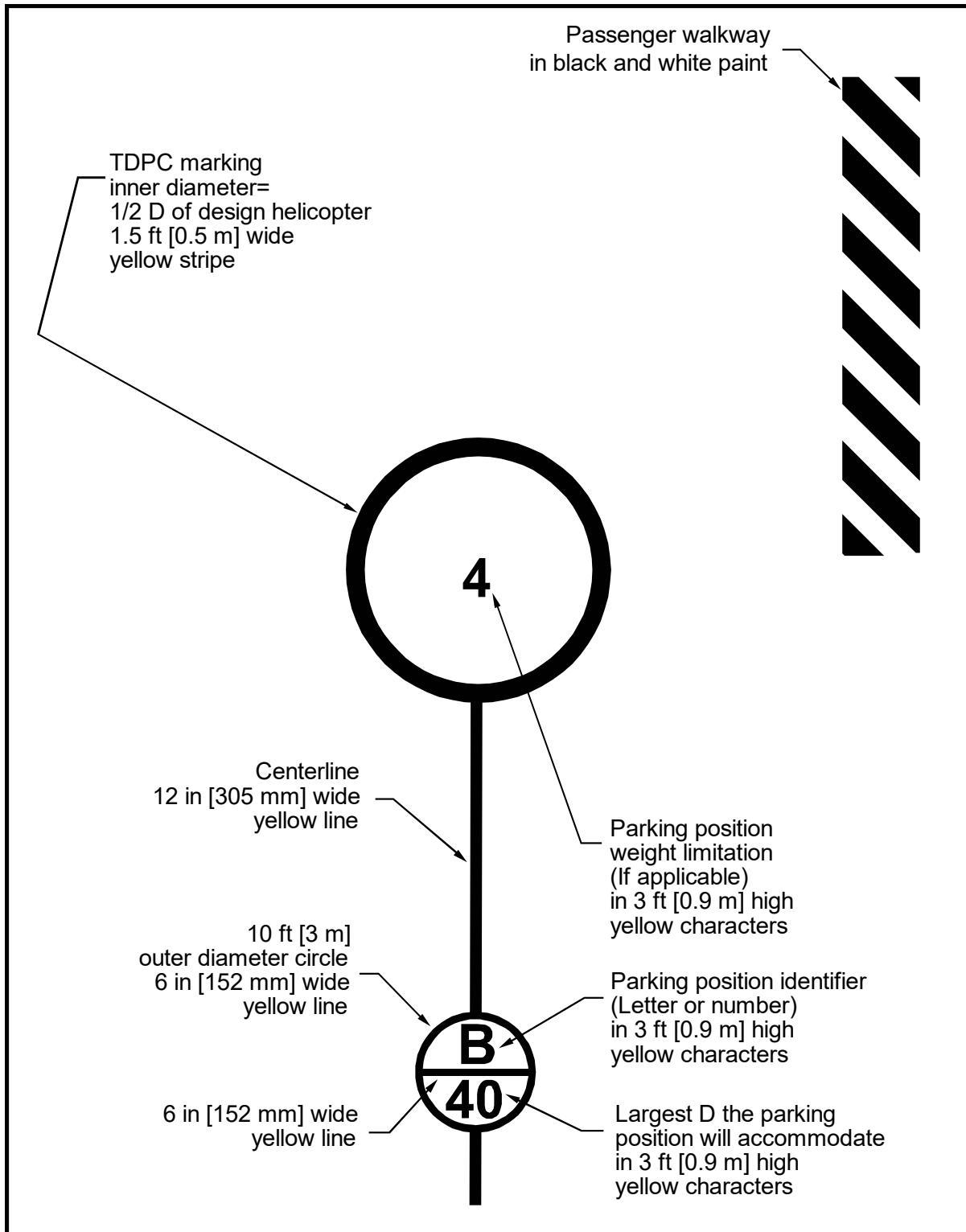
This marking scheme is for paved areas only. For unpaved parking areas, all that is required is the 0.83 D marking, with optional TDPC marking.
See Chapter 4 for guidance on heliport markings.
Figure 3-11. Parking Position Identification, Size, and Weight Limitations – Paved Areas, “Taxi-through” and “Back-out” Parking
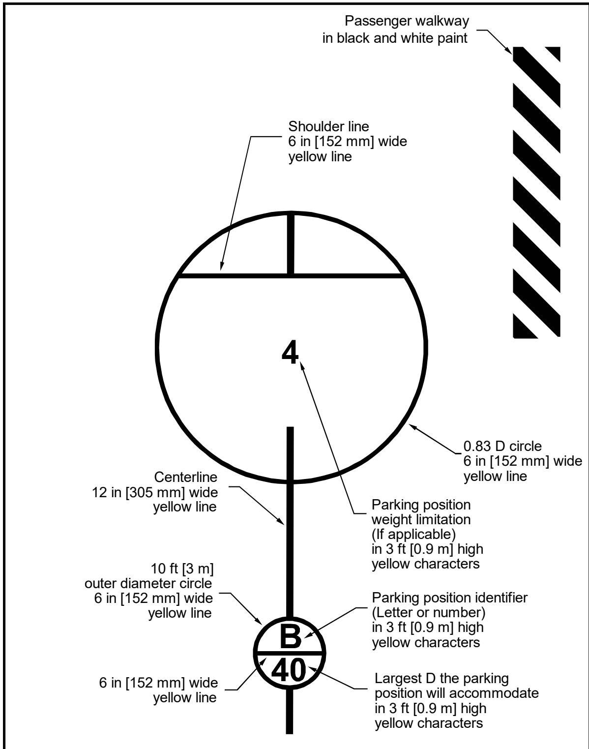
This marking scheme is for paved areas only. For unpaved parking areas, all that is required is the 0.83 D, with optional TDPC marking.
See Chapter 4 for guidance on heliport markings.
3.8 Walkways.
At helicopter parking positions, provide marked ingress/egress walkways where practicable.
Design the pavement to drain away from walkways so spilled fuel does not drain onto walkways or toward parked helicopters.
Locate passenger walkways to minimize passenger exposure to various risks during passenger loading and unloading.
For TRANSPORT heliports, provide marked ingress/egress walkways.
3.9 Fueling.
Design the heliport facility to allow fueling with the use of a fuel truck or a specific fueling area with stationary fuel tanks. Guidelines for design of the fueling area include:
For ground-based heliports, do not locate fueling equipment in the TLOF or FATO.
Do not locate fueling equipment directly under the approach/departure surfaces.
Low profile fueling equipment can be located in the safety area if there is not available room outside the safety area. Low profile fuel dispensing cabinets can be located in one quadrant of a safety area if they are marked and lighted, and the other three quadrants of the safety area are clear. Do not locate the dispensing cabinet directly under approach/departure surfaces.
Design and mark fueling facilities to minimize the potential for helicopters to collide with the dispensing equipment.
Design fueling areas so there is no object tall enough to be hit by the main or tail rotor blades within a distance of D of the design helicopter from the center point of the position where the helicopter would be fueled (providing a minimum of 0.42 D clearance from the rotor tips). If this is not practical at an existing facility, install long fuel hoses.
Provide area lighting of the fueling area if night fueling operations are contemplated. Ensure any light poles do not constitute an obstruction hazard.
Various federal, state, and local requirements for petroleum handling facilities apply to systems for storing and dispensing fuel. Guidance is provided in AC 150/5230-4, Aircraft Fuel Storage, Handling, and Dispensing on Airports. Additional information may be found in various National Fire Protection Association (NFPA) publications. For additional reference material, see Appendix E.
3.10 Tiedowns.
Install recessed tiedowns to accommodate extended or overnight parking of based or transient helicopters.
Recess any tiedowns so they will not be a hazard to helicopters or a trip hazard for personnel. As an option, highlight each tiedown point with a bright contrasting color of paint for pedestrian safety.
Ensure any depression associated with the tiedowns is of a diameter not greater than half the width of the smallest helicopter landing wheel anticipated to be operated on the heliport surface. In addition, provide storage for tiedown chocks, chains, cables, and ropes off the heliport surface to avoid fouling landing gear.
Guidance on recessed tiedowns is provided in AC 20-35, Tiedown Sense.
Page Intentionally Blank
CHAPTER 4. Heliport Markings and Lighting
4.1 General.
This chapter provides guidance on heliport markings and lighting for all three types of heliports and for paved and non-paved surfaces.
4.2 Heliport Retroreflective Markers and Markings.
Markers and/or surface markings identify the facility as a heliport per the following guidelines.
Use paint or preformed materials for surface markings. (See AC 150/5370-10, Item P-620, Runway and Taxiway Marking, for specifications for paint and preformed material.).
As an option, use reflective paint and retroreflective markers, though overuse of reflective material can be blinding to a pilot using landing lights and/or night vision goggles.
As an option, outline lines/markings with a 6-inch (152 mm) wide line of a contrasting color to enhance conspicuity.
Place markings that define the edges of a TLOF, FATO, taxiway, or apron within the limits of those areas.
As an option, use the retroreflective markers and markings, as described in paragraph 4.3 through paragraph 4.12.
Overuse of reflective materials can cause glare to a pilot using landing lights and/or night vision goggles.
4.3 Standard Heliport Identification Marking.
The heliport identification marking (or symbol) identifies the location as a heliport, marks the TLOF, and provides visual cues to the pilot. See Figure 4-1 and Figure 4-2 for dimensional standards for these markings. Guidelines for this marking include:
Locate the “H” in the center of the TLOF and orient it on the axis of the primary or preferred approach/departure path.
Place a one-foot-wide bar under the “H” when it is necessary to distinguish the preferred approach/departure direction. See Figure 4-1.
4.3.1 PPR Heliport Optional (Nonstandard) Heliport Identification Marking.
For a PPR heliport, consider the following:
An optional distinctive marking can be used, such as a company logo, to identify the facility as a PPR heliport.
A nonstandard marking does not necessarily provide the pilot with the same degree of visual cueing as the standard heliport identification symbol.
To compensate for potential decreased visual cueing, increase the size of the safety area to the extent practical when the standard heliport identification symbol “H” is not used.
4.3.2 HOSPITAL Heliports Alternative Identification Marking.
As an alternative to the standard marking for HOSPITAL heliports, use a red “H” with a white 6-inch (152 mm) wide border within a red cross with a 12-inch (0.3 m) wide white border and a surrounding red TLOF.
Where it is impractical to paint the whole TLOF red, paint the TLOF so the minimum dimension (length, width, or diameter) of the outer red area is equal to 0.83 D of the design helicopter but not less than 40 feet (12.2 m). Figure 4-4 illustrates this alternative marking.
4.3.3 Private-use (PVT) Identification Marking.
An optional “PVT” marking may be used to indicate a private-use heliport. Text height is a minimum of 3 feet (0.9 m). The preferred maximum height is 5 feet (1.5 m).
4.3.4 HOSPITAL Heliport: Marking for Winter Operations.
In winter weather at a heliport with a dark TLOF surface, the marking shown in Figure 4-4 will absorb more heat from the sun, may reduce glare, and more readily melt residual ice and snow. In contrast, the white area in Figure 4-3 is more likely to be icy during winter weather. Consequently, in areas that experience ice and snow, use the markings in Figure 4-4 for unheated TLOFs.
Figure 4-1. Standard TLOF Markings
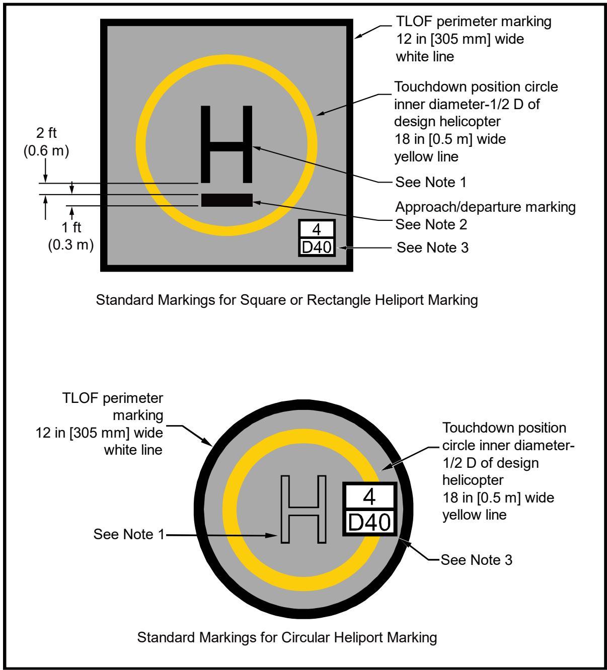
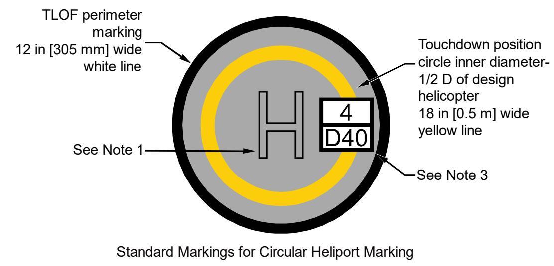
For GENERAL AVIATION and TRANSPORT heliports, mark the TLOF with a white “H” marking (see Figure 4-3). For HOSPITAL heliports, see Figure 4-2, Detail A, for dimensions.
Place a 1-foot black bar 2 feet (0.6 m) below the “H” marking when it is necessary to distinguish the preferred approach/departure direction.
See Figure 4-2, Detail B, for dimensions.
Figure 4-2. Standard Heliport Identification Symbol, TLOF Size and Weight Limitations
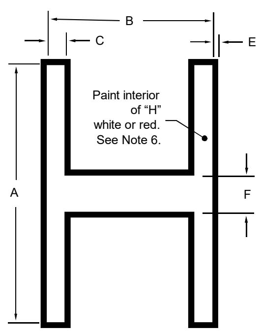
| “H"Size | ||
| Dimension | StandardTLOF marking | AlternateTLOF marking |
| A | 10-0"[3 m] | 0.3D |
| B | 6-8"[2 m] | 0.66A |
| C | 1-0"[0.3 m] | 0.1A |
| E | 0^-3"[76 mm] | 0.02A |
| F | 2-0"[0.6 m] | 0.2A |
Detail A Heliport identification symbol
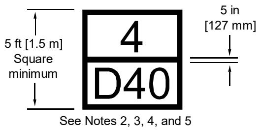
No weight limit
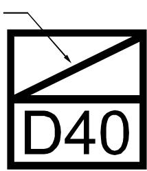
Alternate marking with no weight restrictions
Detail B TLOF size/weight limitation box
See Appendix D for the form and proportion of the numbers used in the TLOF Size and Weight Limitation Box.
Make the minimum size of the box 5 ft (1.5 m) square. Where possible, increase this dimension to a 10 ft (3 m) square for improved visibility.
Characters within the TLOF Size and Weight Limitation Box are black on a white background.
“4” indicates the maximum takeoff weight (4,000 lbs (1,814 kg)) of the TLOF design helicopter, in units of thousands of pounds.
“D40” indicates the controlling dimension D of the largest helicopter (40 ft (12.2 m)) for which the TLOF is designed.
See paragraph 4.4.3 for application of size/weight limitation box.
For GENERAL AVIATION and TRANSPORT heliports, mark the TLOF with a white “H” marking. For HOSPITAL heliports, mark the TLOF with a red “H” in a white cross.
Figure 4-3. HOSPITAL Heliport – Standard Identification Marking
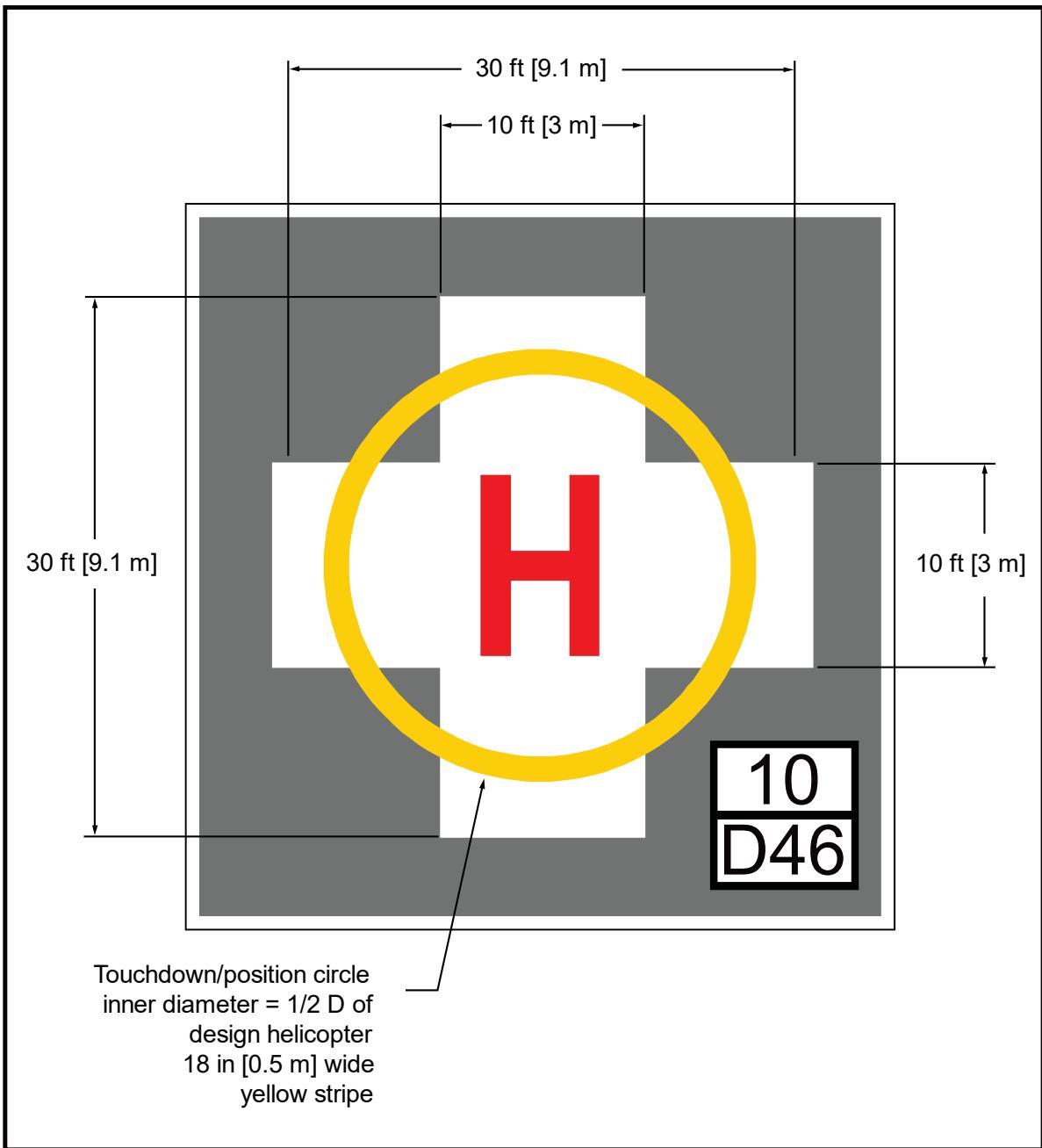
Standard TLOF perimeter strip of 12 inches (0.3 m) wide. See Figure 4-2 for “H”, touchdown position, controlling dimension D, and weight limitation box dimensions.
Figure 4-4. HOSPITAL Heliport – Alternative Identification Marking
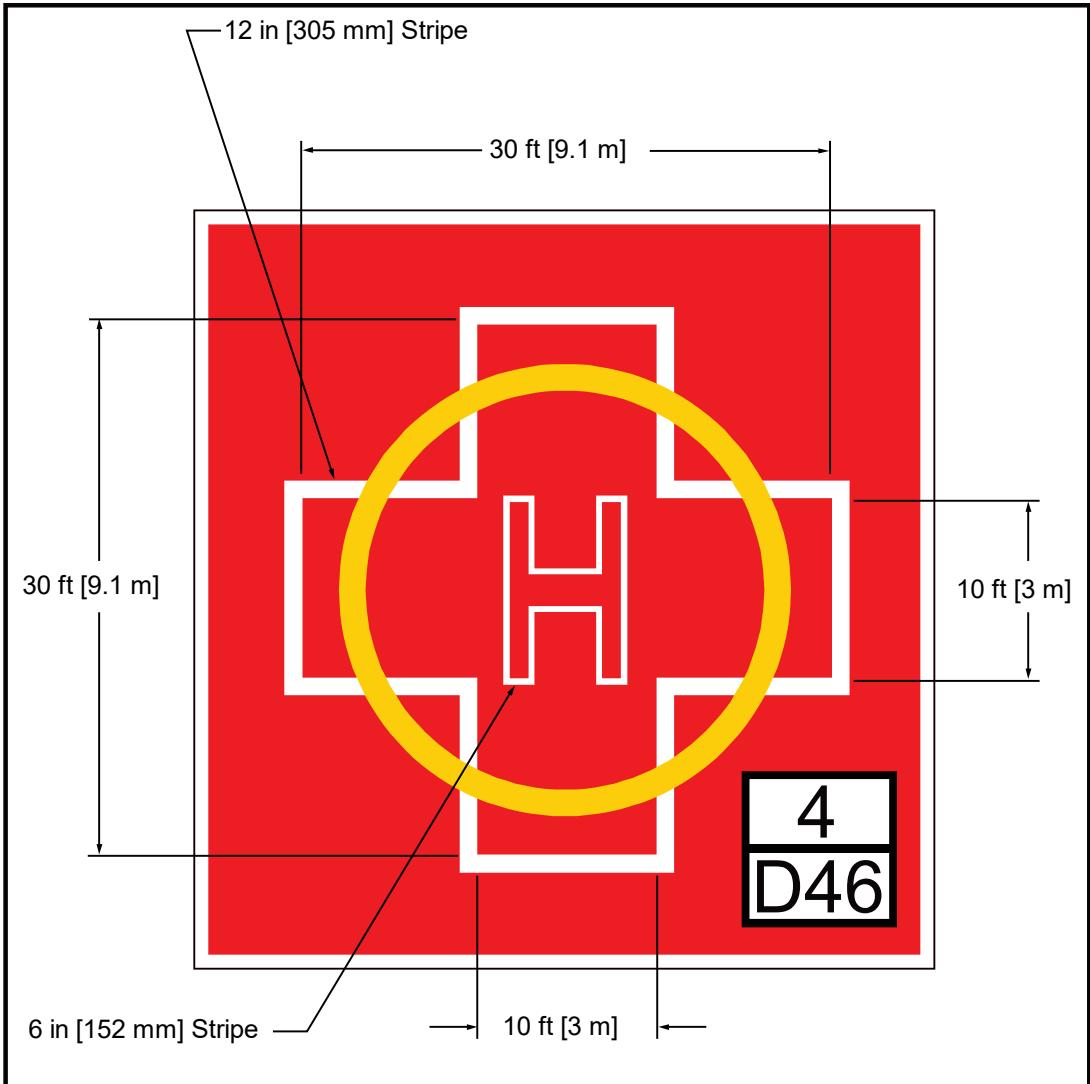
Standard TLOF perimeter strip of 12 inches (0.3 m) wide. See Figure 4-2 for “H”, touchdown position, controlling dimension D, and weight limitation box dimensions.
4.4 TLOF and FATO Markings.
4.4.1 TLOF and Optional FATO Perimeter Retroreflective Markings.
Define the TLOF perimeter with retroreflective markers and/or lines as follows:
If the heliport operator does not mark the TLOF, increase the size of the safety area, as described in paragraph 2.9.
See Figure 4-5 for perimeter markings for TRANSPORT heliports and other paved or hard surfaced TLOFs.
See Figure 4-6 for perimeter markings for unpaved TLOFs at GENERAL AVIATION or HOSPITAL heliports.
Figure 4-5. Paved TLOF/Paved FATO – Paved TLOF/Unpaved FATO – Marking: TRANSPORT Heliports and Other Heliports with a Paved TLOF
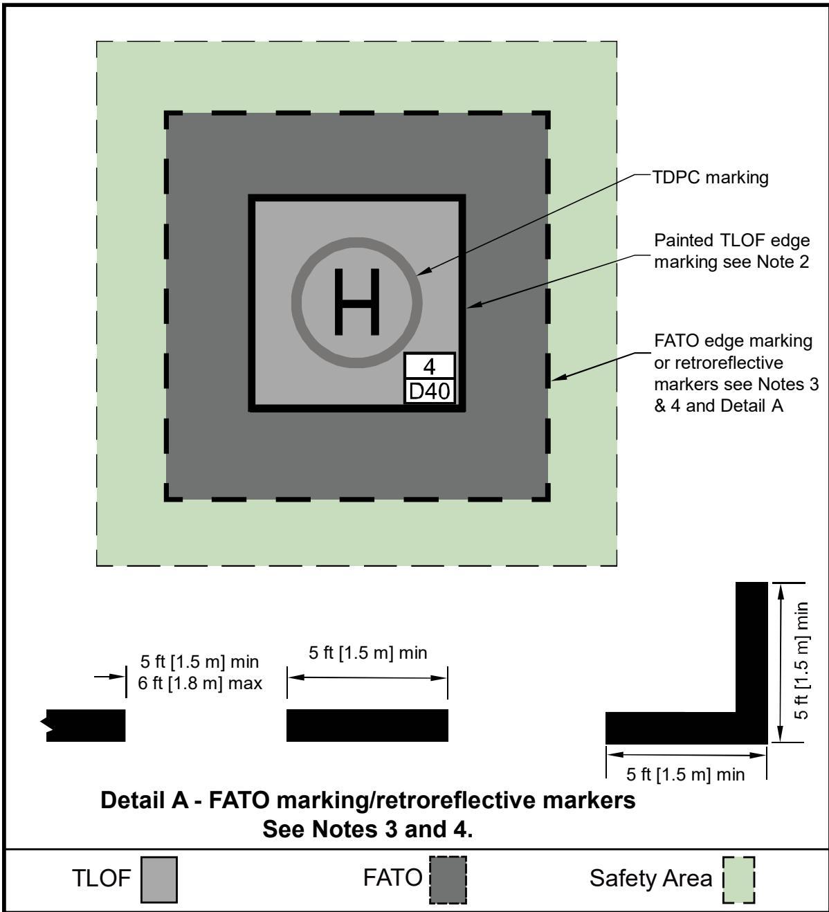
Mark the perimeter of the TLOF and FATO.
Define the perimeter of a paved or hard surfaced TLOF with a continuous 12 inch (0.3 m) white line.
Define paved load-bearing FATO perimeters with a 12 inch (0.3 cm) wide dashed line per Detail A.
Define unpaved load-bearing FATO perimeters with in-pavement retroreflective markers per Detail A.
See Figure 4-2 for “H”, touchdown/position, controlling dimension D, and weight box dimensions.
Figure 4-6. Unpaved TLOF/Unpaved FATO – Marking: GENERAL AVIATION and HOSPITAL Heliports
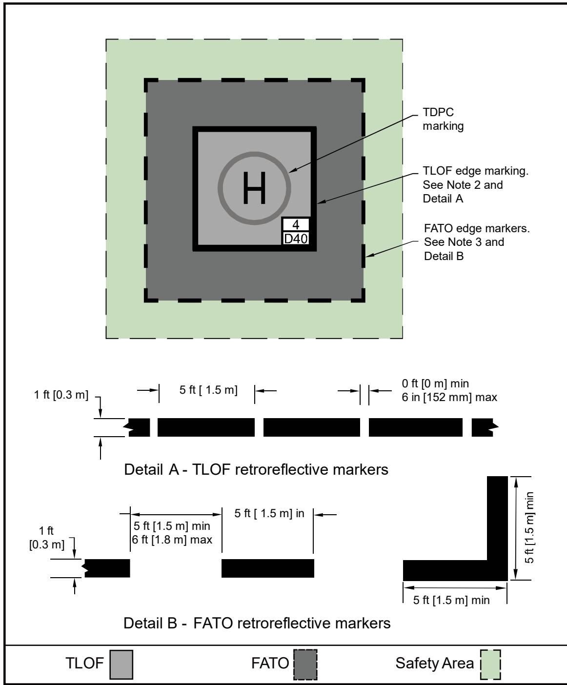
Mark the perimeter of the TLOF.
FATO markings are optional if the TLOF is marked but are included if the TLOF is not marked.
Define an unpaved load-bearing TLOF perimeter with in-pavement retroreflective markers per Detail A.
Define an unpaved load-bearing FATO perimeter with in-pavement retroreflective markers per Detail B.
See Figure 4-2 for “H”, touchdown/position, controlling dimension D, and weight limitation box dimensions.
4.4.2 Touchdown/Positioning Circle (TDPC) Marking.
A TDPC marking provides guidance to allow a pilot to touch down in a specific position within the TLOF. This marking is intended to ensure the pilot’s seat is over the marking, the undercarriage will be inside the LBA, and all parts of the helicopter will be clear of any obstacle by a safe margin.
A TDPC marking is a yellow circle with an inner diameter of 1/2 D and a line width of 18 inches (0.5 m). Locate a TDPC marking in the center of a TLOF. See Figure 4-6.
At PPR heliports, the TDPC marking may be omitted as an option where the TLOF width is less than 16 feet (4.9 m).
4.4.3 TLOF Size and Weight Limitations Markings.
Install size and weight limitations per the following guidelines:
Mark the TLOF to indicate the controlling dimension D and weight of the largest helicopter that the heliport will accommodate, as shown in Figure 4-2.
Place these markings in a box in the lower right-hand corner of a rectangular TLOF, or on the right-hand side of the “H” of a circular TLOF, when viewed from the preferred approach direction.
If necessary, allow the size and weight limitation box marking to interrupt the TDPC marking.
The numbers are black with a white background. See Appendix D for details on the form and proportions of the numbers and letters specified for these markings.
Do not use metric equivalents for this purpose.
These size and weight limitations markings are optional for a TLOF with a turf surface.
These size and weight limitation markings are optional for PPR heliports, since the operator ensures that all pilots using the PPR facility are thoroughly knowledgeable with this and any other facility limitations.
4.4.3.1 TLOF Size Limitation.
This number is the controlling dimension D of the largest helicopter the TLOF will accommodate, as shown in Figure 4-2.
The marking consists of the letter “D” followed by the dimension in feet.
Center this marking in the lower section of the TLOF size/weight limitation box.
4.4.3.2 TLOF Weight Limitations.
If a TLOF has limited weight-carrying capability, mark it with the maximum takeoff weight of the design helicopter, in units of thousands of pounds, as shown in Figure 4-2.
Center this marking in the upper section of a TLOF size/weight limitation box.
For ground-based facilities with no weight limit, add a diagonal line, extending from the lower left-hand corner to the upper right-hand corner, to the upper section of the TLOF size/weight limitation box, as illustrated in Detail B of Figure 4-2.
4.5 Extended Pavement/Structure Markings for GENERAL AVIATION and HOSPITAL Heliports.
As an option, increase the area of the pavement or structure without a corresponding increase in the length and width, or diameter of the FATO, to accommodate pedestrians and/or support operations. Whether or not this increased area is part of the LBA, mark the pavement or area outside the TLOF with 12-inch-wide (0.3 m) diagonal black and white stripes. See Figure 4-7 for marking details.
4.6 FATO Perimeter Markings.
Define the perimeter of a load-bearing FATO with retroreflective markers and/or lines. Do not mark the FATO perimeter if any portion of the FATO is not a load-bearing surface. In such cases, mark the perimeter of the LBA, as described below.
4.6.1 Paved FATOs.
Define the perimeter of a paved load-bearing FATO with a 12-inch-wide (0.3 m) dashed white line. Clearly define the corners of the FATO with these white perimeter markings. The perimeter marking segments are approximately 5 feet (1.5 m) in length, and with end-to-end spacing of approximately 5 feet (1.5 m). See Figure 4-5.
4.6.2 Unpaved FATOs.
Define the perimeter of an unpaved load-bearing FATO with 12-inch-wide (0.3 m) inground retroreflective markers. Clearly define the corners of the FATO with perimeter retroreflective markers. The rest of the perimeter retroreflective markers are 5 feet (1.5 m) long, and have end-to-end spacing of approximately 5 feet (1.5 m). See Figure 4-6.
Figure 4-7. Extended Pavement/Structure Marking: GENERAL AVIATION and HOSPITAL Heliports
Extended pavement structure TLOF edge marki
Extended pavement/structure markings begin in-pavement with TLOF edge markings, and end at the edge, of the extended pavement/structure.
Extended pavement/structure markings are 12 inches (0.3 m) wide black and white stripes on a 45° angle.
4.7 Flight Path Alignment Guidance Marking.
An optional flight path alignment guidance marking consists of one or more arrows to indicate the preferred approach/departure direction(s). Place the guidance marking on the TLOF, FATO, and/or safety area surface, as shown in Figure 2-19.
When combined with a flight path alignment guidance lighting system, described in paragraph 2.12.4, it takes the form shown in Figure 2-19, which includes scheme for marking and lighting the arrows.
The shaft of each arrow is 18 inches (0.5 m) in width and recommended length is 10 feet (3 m).
Use a color which provides good contrast against the background color of the surface.
An arrow pointing toward the center of the TLOF depicts an approach direction.
An arrow pointing away from the center of the TLOF depicts a departure direction.
In the case of a flight path limited to a single approach direction or a single departure path, the arrow marking is unidirectional (e.g., one arrowhead only). In the case of a heliport with only a bidirectional approach/takeoff flight path available, the arrow marking is bidirectional (e.g., two arrowheads).
4.8 Taxiway and Taxi Route Markings.
4.8.1 Paved Taxiway Markings.
For all heliports, mark the centerline of a paved taxiway with a continuous 6-inch (152 mm) yellow line, For TRANSPORT heliports, mark both edges of the taxiway with two continuous 6-inch (152 mm) wide yellow lines spaced 6 inches (152 mm) apart. For GENERAL AVIATION and HOSPITAL heliports, provide optional taxiway edge markings to increase conspicuity. Figure 3-1 illustrates taxiway centerline and edge markings.
4.8.2 Unpaved Taxiway Markings.
Where taxiways are not paved, install either elevated or in-pavement retroreflective edge markers to provide strong visual cues to pilots at both GENERAL AVIATION and HOSPITAL heliports.
Space retroreflective markers longitudinally at approximately 15-foot (4.6 m) intervals on straight segments and at approximately 10-foot (3 m) intervals on curved segments.
Figure 3-2 and Figure 3-3 illustrate these taxiway edge markings/retroreflective markers.
Elevated retroreflective edge markers are blue, 4 inches (102 mm) diameter × 8 inches (203 mm) high maximum cylinder on a 2-inch (51 mm) support.
In-pavement retroreflective edge markers are yellow, 12 inches (0.3 m) wide, and approximately 5 feet (1.5 m) long.
4.8.3 Elevated Retroreflective Edge Markers in Grassy Areas.
Tall grass sometimes obscures elevated retroreflective edge markers. Address this issue by installing 12-inch (0.3 m) diameter solid-material disks around the poles supporting the elevated retroreflective markers. Ensure grass and other vegetation is cut short or removed from around these edge markers to a minimum radius of 2 feet (0.6 m).
4.8.4 Taxiway to Parking Position Transition Requirements.
For paved taxiways and parking areas, taxiway centerline markings continue into parking positions and become the parking position centerlines.
4.9 Helicopter Parking Position Markings.
Helicopter parking positions have the following markings.
4.9.1 Paved Parking Position Identifications.
Mark parking position identifications (numbers or letters) if there is more than one parking position. These markings are yellow characters 36 inches (0.9 m) high. See Figure 3-10 and Figure D-1.
4.9.2 Parking Circle.
Define the circle of radius 0.83 D of the largest helicopter that will park at that position with a 6-inch (152 mm) wide, solid yellow line with an outside diameter of 0.83 D.
In paved areas, this is a painted line (see Figure 3-8 and Figure 3-9).
In unpaved areas, use a series of in-pavement retroreflective markers, 6 inches (152 mm) in width, a maximum of 5 feet (1.5 m) in length, and with end-to-end spacing of approximately 5 feet (1.5 m).
4.9.3 Touchdown/Positioning Circle (TDPC) Marking.
An optional TDPC marking provides guidance to allow a pilot to touch down in a specific position on paved surfaces. When the pilot’s seat is over the marking, the undercarriage will be inside the LBA, and all parts of the helicopter will be clear of any obstacle by a safe margin.
A TDPC marking is a yellow circle with an inner diameter of 1/2 D and a line width of 18 inches (0.5 m).
Locate a TDPC marking in the center of a parking position. See Figure 3-8.
The FAA recommends a TDPC marking for “turn-around” parking areas.
4.9.4 Maximum Length Marking.
This marking on paved surfaces indicates the D of the largest helicopter that the position is designed to accommodate (for example, 49). This marking consists of yellow characters at least 36 inches (0.9 m) high. See Figure 3-10 and Appendix D.
4.9.5 Parking Position Weight Limit.
If a paved parking position has a weight limitation, mark it in units of 1,000 lbs (454 kg), as illustrated in Figure 3-10. (For example, a “4” indicates a weight-carrying capability of up to 4,000 lbs (1,814 kg) a “12” up to 12,000 lbs (5,443 kg).)
Do not use metric equivalents for this purpose.
This marking consists of yellow characters 36 inches (0.9 m) high.
When necessary to minimize the possibility of being misread, place a bar under the number.
See Figure 3-10 and Appendix D for additional parking position weight limit information.
4.9.6 Pavement Shoulder Markings.
As an option, use pavement shoulder markings for paved parking areas (Figure 3-9) to ensure safe rotor clearance.
Install a 6-inch (152 mm) wide solid yellow shoulder line, perpendicular to the centerline and extending to the 0.83 D marking, so it is under the pilot’s shoulder such that the main rotor of the largest helicopter the position will accommodate will be entirely within the rotor diameter parking circle (see Figure 3-9).
Use 1/4 D from the center of the parking area to define the location of shoulder line.
The FAA recommends a shoulder line marking for both “taxi-through” and “backout” parking areas.
4.10 Walkways.
Figure 3-10 illustrates one marking scheme for walkways.
4.11 Closed Heliport.
Remove all markings of a permanently closed heliport, FATO, or TLOF. If it is impractical to remove the markings, place a yellow “X” over the $\mathbf { \bar { \Sigma } } ^ { \mathsf { e } } \mathbf { \Psi } \mathbf { H } ^ { \mathsf { p } } )$ , as illustrated in Figure 4-8.
For temporary heliport closures, as an option, place a yellow “X” over the “H”. See Figure 4-8.
Make the yellow “X” large enough to ensure early pilot recognition that the heliport is closed.
Remove the wind cone(s) and other visual indications of a closed heliport.
Turn off and disconnect heliport perimeter lighting and other lighting for the heliport.
Figure 4-8. Marking a Closed Heliport
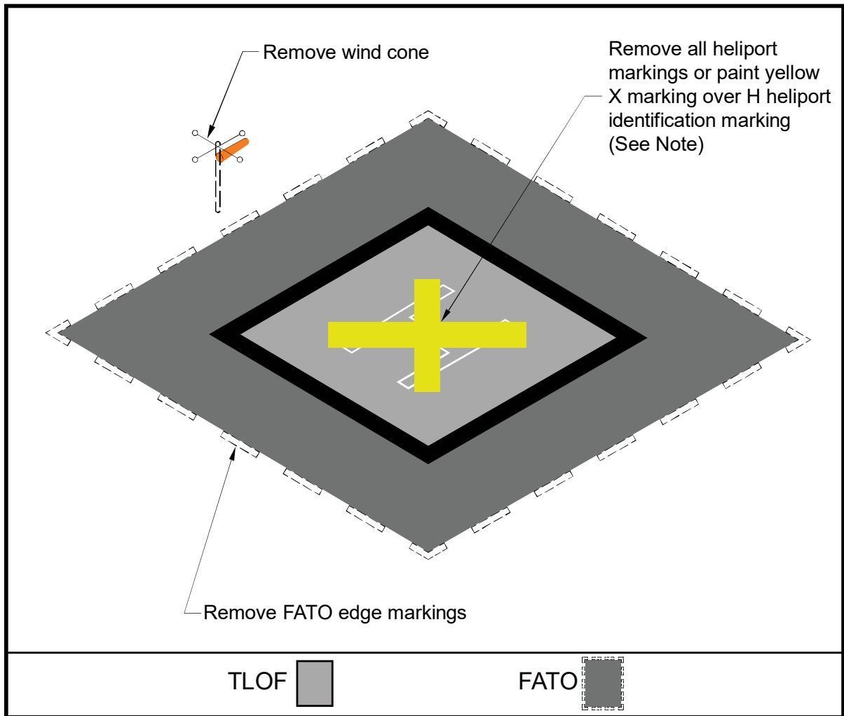
See paragraph 4.11 for guidance on removal of markings for permanent or temporary heliport closures.
4.12 Marking Sizes.
See Appendix D for guidance on the proportions and sizes of painted numbers and letters.
4.13 Heliport Lighting.
Heliports that support night operations under visual meteorological conditions or instrument meteorological conditions for either day or night operations are lighted with TLOF and/or optional FATO perimeter lights, as described below. FATO perimeter lights may be used as an option under special circumstances to improve visual acquisition of the approach path and/or landing environment due to varying degrees of ambient light, proximity to airport taxiways, etc.
Install FAA type L-860H elevated and/or FAA type L-852H in-pavement light fixtures for heliport perimeter applications for VMC applications.
Light intensity and horizontal/vertical light distribution are characterized.
The light emitting diode (LED) elevated heliport fixture and LED in-pavement fixture will be identified as: L-860H (L) and L-852H (L), respectively.
Any of these fixtures may be used as flight path alignment lights or landing direction lights.
See Appendix G for heliport perimeter lighting design requirements.
4.13.1 In-pavement TLOF Perimeter Lights.
Install TLOF perimeter lights, per the guidelines below, as shown in Figure 4-9, Figure 4-10, and Figure 4-11.
Install FAA type L-852H in-pavement green lights meeting the requirements in Appendix G to define the TLOF perimeter.
For heliports where only the TLOF is load-bearing, install FAA type L-852H inpavement green lights or, as an option, install elevated green omnidirectional lights.
Use a minimum of four light fixtures per side of a square or rectangular TLOF. For HOSPITAL and PPR Heliports, as an option, use a minimum of three light fixtures per side of a square or rectangular TLOF.
Use an odd number of lights on each side to place lights along the centerline of the approach.
Locate a light at each corner, with additional lights uniformly spaced between corner lights. Space the lights at a maximum of 25 feet (7.6 m).
For a circular TLOF, use an even number of lights, with a minimum of eight, uniformly spaced.
Locate in-pavement lights within 1 foot (0.3 m) inside or outside of the TLOF perimeter.
Locate elevated lights outside and within 10 feet (3 m) of the edge of the TLOF. Ensure elevated lights do not penetrate a horizontal plane at the TLOF elevation by more than 2 inches (51 mm).
As an option for TLOF lights at TRANSPORT heliports, install a line of 7 green, in-pavement lights meeting the standards in Appendix G. Space these lights at 5- foot (1.5 m) intervals in the TLOF pavement. Align these lights on the centerline of the approach course to provide close-in directional guidance and improve TLOF surface definition. See Figure 4-11.
For PPR heliports, install in-pavement TLOF lights. As an option, if the FATO is load-bearing, use elevated omnidirectional lights. For private-use heliports, install elevated omnidirectional or in-pavement lighting in the TLOF as appropriate to site specific surface materials, elevations, and weather conditions.
Mount perimeter lights on the outer edge of the pavement or structure or the inner edge of the safety net as an option when the pavement or structure is larger than the TLOF.
Figure 4-9. Elevated TLOF – Perimeter Lighting
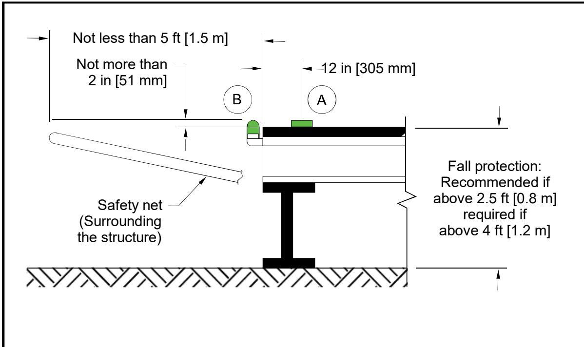
Install either “A” Type L-852H, or “B” Type L-860H.
In-pavement edge light fixture Ⓐ (Type L-852H).
Omnidirectional light Ⓑ, mounted off the structure edge (Type L-860H).
Ensure elevated lights do not penetrate a horizontal plane at the TLOF elevation by more than 2 inches (51 mm).
For TLOF and FATO lighting requirements, see Appendix G.
A safety net’s supporting structure should be located below the safety net.
Figure 4-10. TLOF/FATO Perimeter Lighting
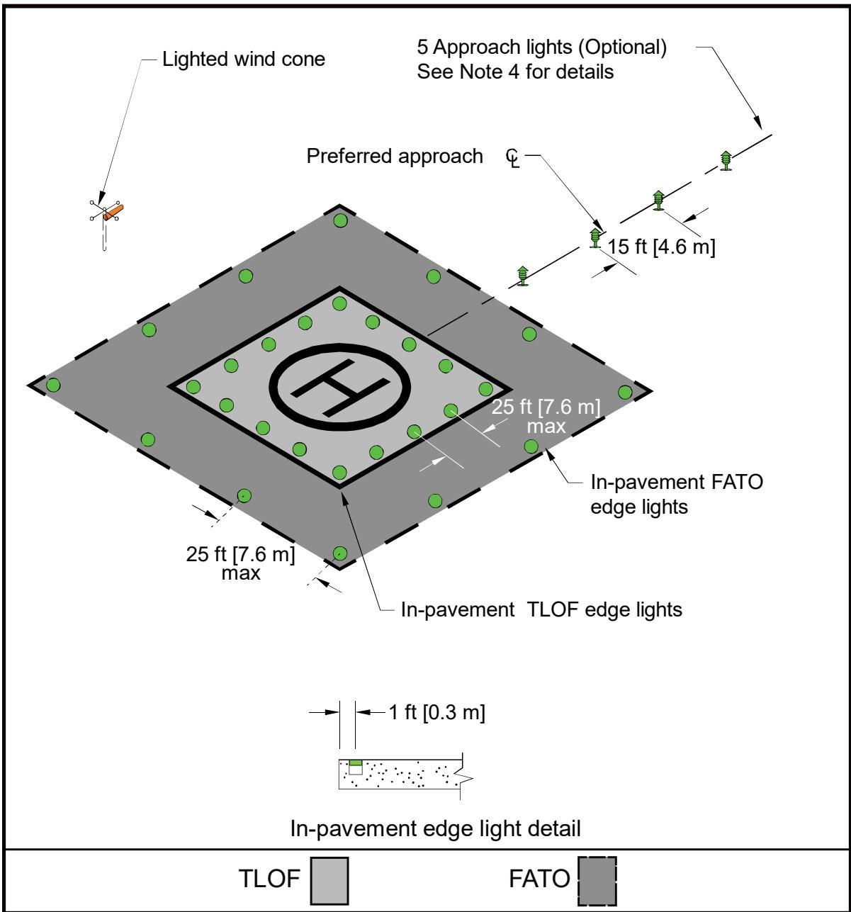
Install in-pavement TLOF perimeter lights inside or outside within 1 ft (0.3 m) of the FATO and TLOF respective perimeters. FATO lighting installation is optional but may be installed for specific applications.
TLOF/FATO Lighting: 25 ft (7.6 m) maximum spacing, 4 lights per side minimum.
Approach Lighting: 15 ft (4.6 m) spacing. Elevated FATO omnidirectional lights (optional).
Install in-pavement edge light fixtures in accordance with the requirements of AC 150/5340-30.
For TLOF and FATO lighting requirements, see Appendix G.
Figure 4-11. TLOF In-pavement and FATO Elevated Perimeter Lighting
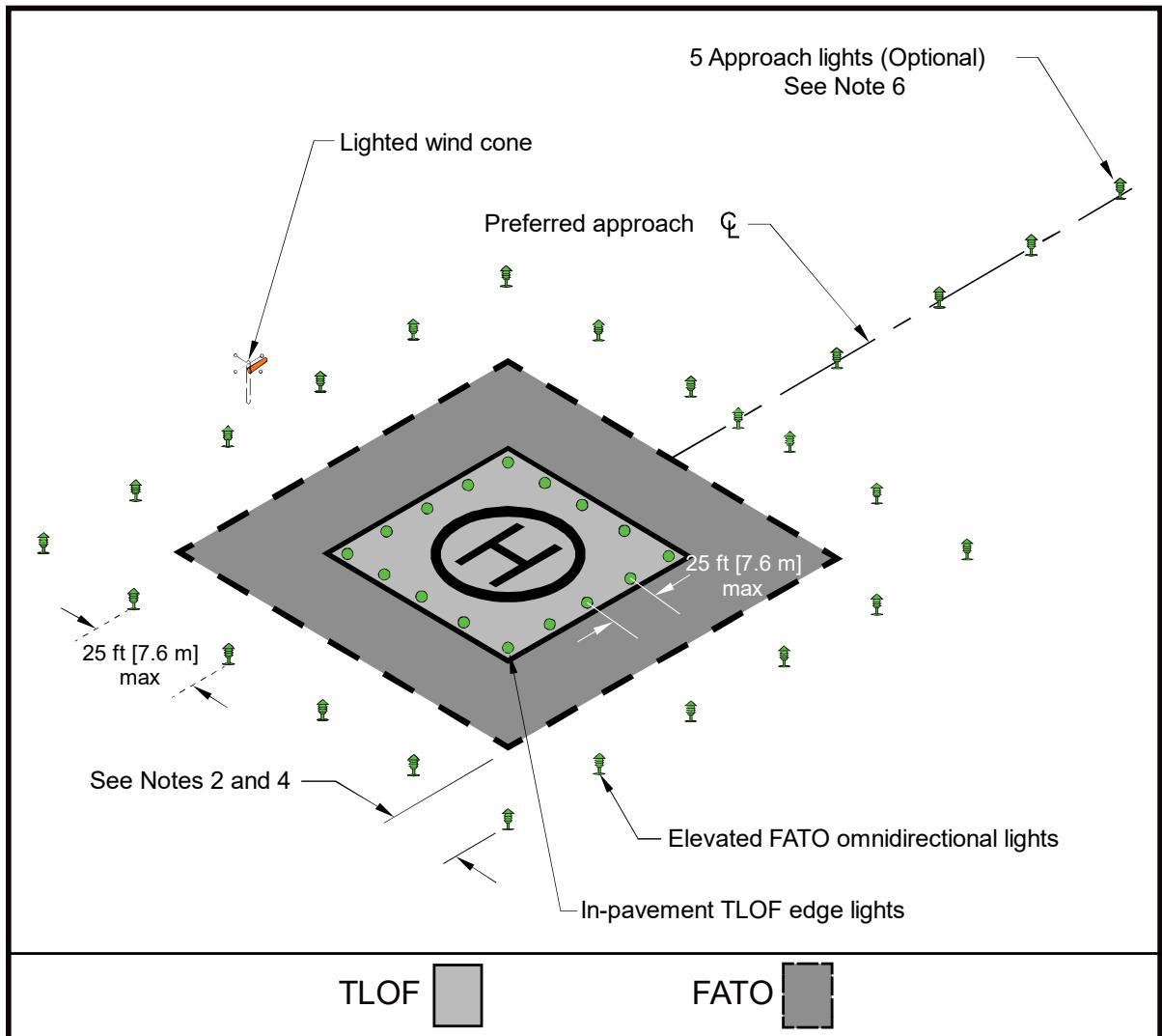
Install in-pavement FATO and TLOF perimeter lights inside or outside within 1 ft (0.3 m) of the FATO and TLOF respective perimeters.
Locate a light at each corner with additional lights uniformly spaced between the corner lights with a maximum spacing of 25 feet (7.6 m) between lights.
Install an odd number of edge lights on each side to place lights along the centerline of the approach.
Install elevated FATO lights 10 ft (3 m) outside the FATO perimeter.
TLOF/FATO Lighting: 25 ft (7.6 m) maximum spacing, 4 lights per side minimum.
Position the approach lights with 15 ft (4.6 m) spacing.
Elevated FATO omnidirectional lights. See Appendix G.
Ensure the elevated lights do not penetrate a horizontal plane at the TLOF elevation by more than 2 inches (51 mm).
4.13.2 Perimeter Lights for Elevated TLOFs.
As an option for heliports, use elevated, omnidirectional lights meeting the requirements of Appendix G.
Locate these lights on the outside edge of the TLOF.
Ensure the elevated lights do not penetrate a horizontal plane at the TLOF edge elevation by more than 2 inches (51 mm). See Figure 4-9.
4.13.3 Optional FATO Perimeter Lights
Design guidelines for optional FATO perimeter lights are provided below for TRANSPORT heliports, GENERAL AVIATION and HOSPITAL heliports as these guidelines are distinct for each type of heliport, as shown in Table 4-1. See also Figure 4-10, Figure 4-11, and Figure 4-12.
When a heliport on an airport is sited near an aircraft taxiway, there may be a concern that a pilot may confuse the green taxiway centerline lights with the FATO perimeter lights. As an option in such cases, use yellow lights as an alternative color for marking the FATO.
Table 4-1. FATO Perimeter Light Design
| TRANSPORT FATO | GA/HOSPITALLoad-bearing FATO | |
| Lights | Use green lights meeting therequirements of Appendix Gto define the limits of theFATO. | • Use green lights meeting the requirements ofAppendix G to define the perimeter of a load-bearing FATO. Do not light the FATO perimeter if anyportion of the FATO is not a load-bearingsurface. |
| Locationand spacing | • See Figure 4-11 for lightspacing and layout. | Install a minimum of four (minimum of threelights for PPR and HOSPITAL heliports) in- pavement per side of a square or rectangularFATO.• Space lighting 25 ft (7.6 m) maximumspacing. |
| Installationguidance | • Mount frangible elevatedlight fixtures 10 feet (3 m) outfrom the FATO perimeter.• Ensure they do not penetrate ahorizontal plane at theadjacent TLOF elevation bymore than 2 inches (51 mm). | • N/A |
| ElevatedFATO | Lighting for an elevatedFATO is the same as for aground-level FATO.Ensure the elevated lights donot penetrate a horizontalplane at the adjacent TLOF | • In the case of an elevated FATO with a safetynet, mount the perimeter lights, as described in paragraph 4.13.2.• As an option, locate elevated FATO perimeterlights, no more than 2 inches (51 mm) high, |
| elevation by more than 2 inches (51 mm). | 10 feet (3 m) from the FATO perimeter. See Figure 4-11. Ensure the elevated lights do not penetrate a horizontal plane at the adjacent TLOF elevation by more than 2 inches (51 mm). | |
| Circular FATO | • N/A | To define a circular FATO, use an even number of lights, with a minimum of eight light fixtures uniformly spaced. Locate in-pavement lights within 1 foot (0.3 m) inside or outside of the FATO perimeter See Figure 4-10. As an option, use a square or rectangular pattern of FATO perimeter lights even if the TLOF is circular. At a distance during nighttime operations, a square or rectangular pattern of FATO perimeter lights may provide the pilot with better visual alignment cues than a circular pattern, but a circular pattern may be more effective in an urban environment. |
Figure 4-12. FATO Elevation
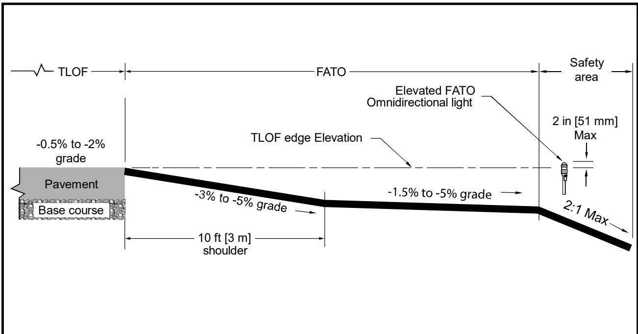
See paragraph 4.13.3 for guidance on FATO lights.
4.13.4 Floodlights.
The FAA has not evaluated floodlights for effectiveness in visual acquisition of a heliport. Guidelines for the use and installation of floodlights includes:
TRANSPORT Heliports – Install floodlights to illuminate the helicopter parking areas.
GENERAL AVIATION and HOSPITAL Heliports – Install floodlights to illuminate the TLOF, the FATO, and/or the parking area if ambient light does not suitably illuminate markings for night operations.
Mount these floodlights on adjacent buildings to eliminate the need for tall poles, if possible. Place floodlights clear of the TLOF, the FATO, the safety area, the approach/departure surfaces, and transitional surfaces and ensure floodlights and their associated hardware do not constitute an obstruction hazard.
Aim floodlights down to provide adequate illumination on the apron and parking surface.
Ensure floodlights that might interfere with pilot vision during takeoff and landings are capable of being turned off by pilot control or at pilot request.
Note 1: Floodlights do not replace TLOF or FATO lighting recommendations.
Note 2: White lighting for heliport applications should not be activated until the aircraft has landed and deactivated prior to takeoff.
4.13.5 Landing Direction Lights.
Install landing direction lights when it is necessary to provide directional guidance to indicate available approach and/or departure path directions as an option, as follows:
Landing direction lights are a configuration of five green, omnidirectional lights meeting the standards of Appendix G, located on the centerline of the preferred approach/departure paths.
Space these lights at 15-foot (4.6 m) intervals extending outward in the direction of the preferred approach/departure paths, with spacing and layout, as illustrated in Figure 4-13.
Figure 4-13. Landing Direction Lights.
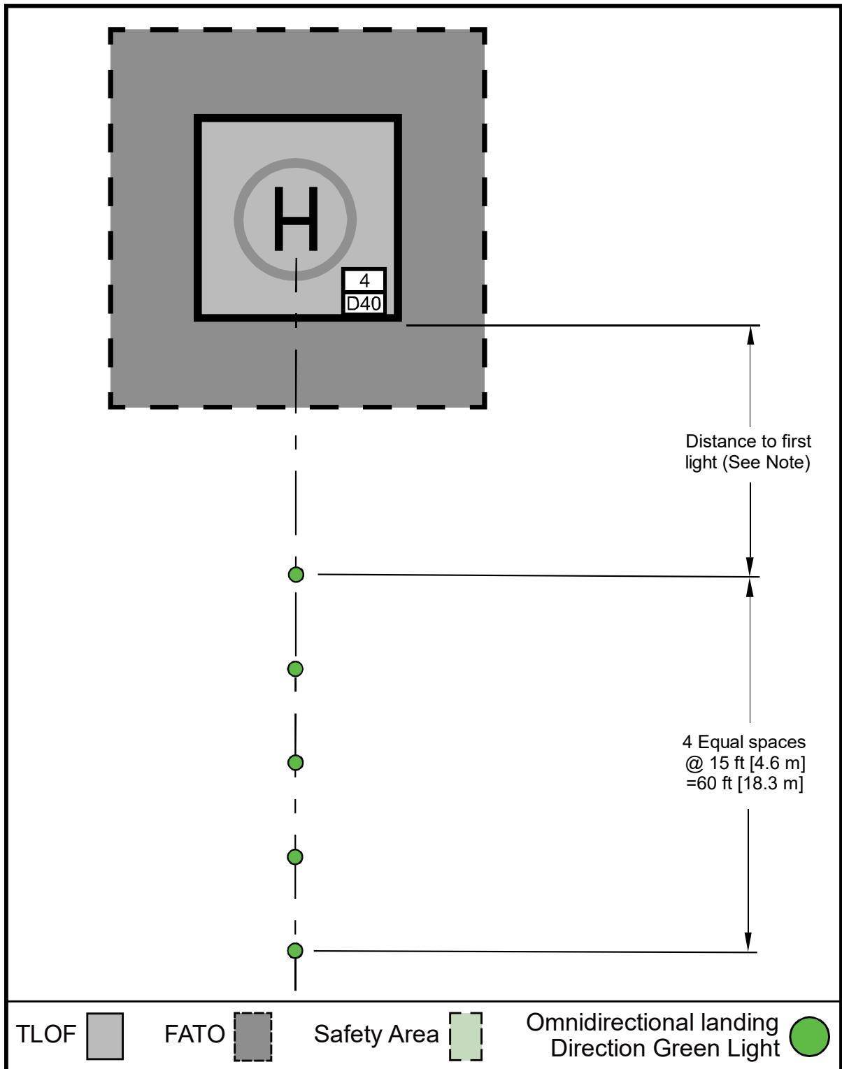
Locate the first omnidirectional landing direction light 20-60 ft (6.1-18.3 m) from the TLOF for GENERAL AVIATION and HOSPITAL heliports, and 30-60 ft (9.1-18.3 m) from the TLOF for TRANSPORT heliports.
See paragraph 4.13.5 for guidance on landing direction lights.
4.13.6 Flight Path Alignment Lights.
Flight path alignment lights provide approach and/or departure path directions in a straight line along the direction of approach and/or departure flight paths. If necessary, they may extend across the TLOF, FATO, safety area, or any suitable surface in the immediate vicinity of the FATO or safety area. Use three or more green lights spaced at 5 ft (1.5 m) to 10 ft (3 m).
Install flight path alignment lights meeting the requirements of Appendix G as an option.
Place these lights in a straight line along the direction of approach and/or departure flight paths.
Extend the lights across the TLOF, FATO, safety area, or any suitable surface in the immediate vicinity of the FATO or safety area, if necessary.
Install three or more green lights spaced at 5 feet (1.5 m) to 10 feet (3 m). See Figure 2-19.
4.13.7 Taxiway and Taxi Route Lighting.
4.13.7.1 Optional Taxiway and Taxi Route Lighting.
Install taxiway centerline lights per the following guidelines:
Install in-pavement bidirectional green taxiway centerline lights meeting the standards of AC 150/5345-46, Specification for Runway and Taxiway Light Fixtures, for type L-852A (straight segments) or L-852B (curved segments).
Space these lights at maximum 50-foot (15.2 m) longitudinal intervals on straight segments and at maximum 25-foot (7.6 m) intervals on curved segments, using a minimum of four lights to define the curve.
Uniformly offset the taxiway centerline lights no more than two feet (0.6 m) to facilitate painting of the taxiway centerline.
For GENERAL AVIATION and HOSPITAL Heliports, green retroreflective markers can be used as an option in lieu of the L-852A or L-852B lighting fixtures.
Use Type I retroreflective markers, as described in AC 150/5345-39, Specification for L-853, Runway and Taxiway Retroreflective Markers.
Do not use retroreflective markers for TRANSPORT heliports.
4.13.7.2 Optional Taxiway Edge Lights.
Specify taxiway edge lights per the following guidelines:
For paved taxiways, use type L-852T in-pavement omnidirectional blue lights meeting the standards of AC 150/5345-46 to mark the edges of a taxiway.
Use type L-861T elevated lights meeting the standards of AC 150/5345-46. The lateral spacing for the lights or reflectors is equal to 0.83 D of the design helicopter, but not more than 35 feet (10.7 m).
For unpaved taxiways at GENERAL AVIATION and HOSPITAL heliports, blue retroreflective markers may be used in lieu of lights.
Ensure retroreflective markers are no more than 8 inches (203 mm) tall.
TRANSPORT heliports cannot use retroreflective markers.
Install taxiway edge lights per AC 150/5340-30.
For straight segments, space taxiway edge lights at 50-foot (15.2 m) longitudinal intervals on straight segments.
Curved taxiway segments require smaller spacing of edge lights. The light spacing is based on the radius of the curve, as described in AC 150/5340-30. Space taxiway edge lights uniformly. On curved edges of more than 30 degrees from point of tangency (PT) of the taxiway section to PT of the intersecting surface, install at least three edge lights. For radii not listed in AC 150/5340-30, determine spacing by linear interpolation.
4.13.8 Heliport Identification Beacon.
A heliport identification beacon may be used to provide the pilot with a means of visually locating the heliport. The identification beacon is a flashing white/green/yellow with a rate of 30 to 45 flashes per minute. Install beacons per the guidance below:
Install heliport identification beacons for TRANSPORT heliports.
These beacons are optional for GENERAL AVIATION and HOSPITAL heliports. Beacons at these heliports can be pilot controlled (as an option) such that the beacon is “on” only when needed.
Specify a beacon meeting the guidelines provided by AC 150/5345-12, Specification for Airport and Heliport Beacon.
Locate and install the beacon per AC 150/5340-30.
Page Intentionally Blank
CHAPTER 5. Helicopter Facilities on Airports
5.1 General.
5.1.1 This chapter addresses design considerations for separate helicopter facilities on airports. Helicopters can operate on airports without interfering with airplane traffic. Operations can occur on existing airport infrastructure (e.g., on airport taxiways) or on dedicated heliport facilities, as shown in Figure 5-1. Separate heliport facilities and approach/departure procedures may be needed when the volume of airplane and/or helicopter traffic affects operations.
5.1.2 At airports with interconnecting passenger traffic between helicopters and airlines, provide gates at the terminal for helicopter boarding. People who use a helicopter to go to an airport generally need convenient access to the airport terminal and the services provided to airplane passengers.
5.1.3 Identify the location of the exclusive-use helicopter facilities, TLOFs, FATOs, safety areas, approach/departure paths, and helicopter taxi routes and taxiways on the ALP. Figure 5-1 shows an example of dedicated heliport facilities located on an airport. Other potential heliport locations are on the roofs of passenger terminals or parking garages serving passenger terminals.
5.2 Touchdown and Liftoff Area (TLOF).
Locate the TLOF to provide ready access to the airport terminal or to the helicopter user’s origin or destination. Locate the TLOF away from aircraft movement areas (runways, taxiways, and aircraft parking aprons).
5.3 On-Airport Location of Final Approach and Takeoff Area (FATO).
See Table 5-1 for standards of the distance between the centerline of an approach to a runway and the centerline of an approach to a FATO for simultaneous, same direction, VFR operations.
Figure 5-1. Example of Heliport Facilities Located on an Airport
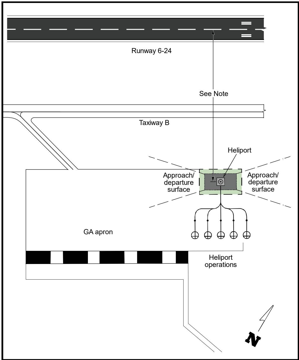
See Table 5-1.
Table 5-1. Recommended Distance between FATO Center to Runway Centerline for VFR Operations
| Airplane Size | Small Helicopter7,000 Ibs (3,175 kg)or less | Medium Helicopter7,001 (3,176 kg) to12,500 Ibs (5,670 kg) | Large Helicopterover 12,500 Ibs(5,670 kg) |
| Small airplane12,500 1bs (5,670 kg)or less | 300 feet(91 m) | 500 feet(152m) | 700 feet(213 m) |
| Large airplane12,500 1bs (5,670 kg)to 300,000 1bs(136,079 kg) | 500 feet(152m) | 500feet(152m) | 700 feet(213 m) |
| Heavy airplaneOver 300,000 1bs(136,079 kg) | 700 feet(213 m) | 700 feet(213 m) | 700 feet(213 m) |
5.4 Safety Area.
Apply the safety area dimensions and clearances, described in Chapter 2, to heliport facilities being developed on an airport.
5.5 VFR Approach/Departure Paths.
To the extent practical, design helicopter approach/departure paths to be independent of approaches to, and departures from, active runways.
5.6 Heliport Protection Zone (HPZ).
Establish an HPZ, where practicable, for the airport owner to acquire the land area. Plan the land uses within the HPZ. Where not practicable, the HPZ standards have recommendation status for that portion of the HPZ the airport owner does not control.
5.7 Taxiways and Taxi Routes.
When developing exclusive helicopter taxiways or taxi routes at an airport, locate these routes to minimize interaction and/or conflicts with airplane operations. Consider the rotor wash generated by the largest design helicopter anticipated to operate at the facility when determining helicopter taxiway and taxi route distances from airplane operations.
5.8 Helicopter Parking.
Locate helicopter parking positions as close to the intended destination or origination of the passengers as conditions and safety permit. See Chapter 3 for guidance on helicopter parking requirements.
5.9 Security.
Unless screening was carried out at the helicopter passengers’ departure location, Transportation Security Administration regulations may require that a screening area and/or screening be provided before passengers re-enter the airport’s secured areas. If necessary, establish multiple helicopter parking positions and/or locations in the terminal area to service helicopter passenger screening and/or cargo interconnecting needs. Find information about passenger screening on the Transportation Security Administration website https://www.tsa.gov/public/.
CHAPTER 6. Instrument Operations
6.1 General.
This chapter provides guidance on heliport markings and lighting for GENERAL AVIATION, TRANSPORT, and HOSPITAL heliports. Ensure that at least one of the following visual references is visible or identifiable before the pilot proceeds visually for departure/approach:
FATO lights.
TLOF lights.
Heliport Instrument Lighting System (HILS).
Heliport Approach Lighting System (HALS) or lead-in lights.
Visual Glideslope Indicator (VGSI).
Windsock or windsock light(s). See note below.
Heliport beacon. See note below.
Other facilities or systems approved by the Flight Technologies and Procedures Division (AFS-400).
Locate windsock lights within 500 ft (152 m) of the TLOF.
6.1.1 Instrument flight procedures permit helicopter operations to continue during periods of low cloud ceilings and reduced visibility. Instrument procedures include approach procedures, departure procedures, and missed approach procedures.
6.1.2 The FAA establishes instrument approach procedures under FAA 8260-series Orders overseen by the FAA Flight Procedures and Airspace Group. When a procedure applies to a private (non-public) heliport, is developed for one specific user, or is developed by a non-FAA service provider using unique FAA-approved instrument criteria, the instrument procedure is a “special” instrument procedure. After approval by the FAA, the special instrument procedure is issued to the operator approved to fly the procedure.
6.1.3 See Table 6-1 for instrument approach procedure requirements for precision approaches, non-precision approaches, and approaches to point-in-space.
Table 6-1. Standards for Instrument Approach Procedures
| Precisionapproachto IFRheliport | Precisionapproachto IFRheliport | Non-precisionapproach to IFRheliport | Approach topoint-in-space, proceed|space, proceedvisually | Approach topoint-in-space, proceed|space, proceedVFR | |
| Visibilityminimums | 1/4 statuemile(0.4 km) | 1/2 statuemile(0.8 km) 1 | HAL=250-600:1/2statute mile (0.8 km)HAL=601-800: 3/4statute mile (1.2 km)HAL>800: 1 statutemile (1.5 km) | 3/4 statute mile(i(1.2 km) day 6 | 3/4 statute mile(1.2 km) day,1 statute mile(1.5 km) night |
| Authorizedminima | ≥200 ft(61 m) AGL|i | ≥200(i61 m) AGL | ≥250(76 m) AGL | ≥250(76 m) AGL | ≥250(76 m) AGL |
| Heliport type | IFR | IFR | IFR | VFR | VFR |
| ocs | 34:1 Clear 2i | 34:1 Clear2 | Standard Non-precision ROC | 8:1 | 8:1 |
| Heliport size 5 | Depends ondesignhelicopter | Depends ondesignhelicopter | Depends on designhelicopter | Depends ondesignhelicopter | Depends ondesignhelicopter |
| Heliportmarkings | SeeChapter 4 | SeeChapter 4 | SeeChapter 4 | SeeChapter 4 | SeeChapter 4 |
| Heliport lights 3 | Required | Required | Required | Required | Required |
| Survey required | Yes | Yes | Yes | Yes | No |
| Approach lights(HALS) | Yes | No | No | No | No |
| HPZ helicopterprotection | Yes | Yes | Yes | Yes | Yes |
| Final approachreference area | Yes | Yes4 | No | No | No |
1/4 statute mile (0.4 km) reduction authorized with HALS aligned to approach angle and course.
Minimum glidepath angle of 3 degrees.
Either TLOF or FATO must be lit at night.
FARA only required for instrument landing system/localizer-only approaches (ILS/LOC) approaches.
Minimum heliport size dependent on type of heliport (GENERAL, HOSPITAL, TRANSPORT).
Proceed visually minimum visibility is 3/4 statute mile (1.2 km) maximum visibility based on distance from missed approach point/descent altitude (MAP/DA) to landing location.
If HAL greater than 800 ft (244 m) MSL visibility day and night 1 statute mile (1.6 km).
6.2 Planning.
This chapter addresses issues that heliport owners consider before requesting the development of instrument approach/departure/missed approach procedures. The standards and recommendations in this AC are not intended to be sufficient to design an instrument procedure. A heliport sponsor should initiate early contact with the appropriate FAA Flight Standards Office to plan for and establish instrument procedures.
6.3 Airspace.
Those who design instrument approach/departure/missed approach procedures have some flexibility in the design of such procedures. For this and other reasons, the airspace required to support helicopter instrument approach/departure operations is complex, and it does not lend itself to simple descriptions or the use of figures. Refer to the latest revision of FAA 8260-series Orders for more detailed information on criteria for developing helicopter instrument approach/departure/missed approach procedures.
6.4 Final Approach Reference Area (FARA).
For precision instrument procedures only, a certificated helicopter precision approach procedure terminates with the helicopter coming to a hover or touching down within a 150-foot-wide (46 m) by at least 150-foot long (46 m) FARA. The FARA is located at the far end of a 300-foot-wide by 1,225-foot-long (91 m by 373 m) FATO required for a precision instrument procedure. For the purposes of requirements for LBA and lighting, substitute the FARA for the FATO. Figure 6-1 illustrates the FARA/FATO relationship.
Figure 6-1. FARA/FATO Relationship: Precision Instrument Procedure
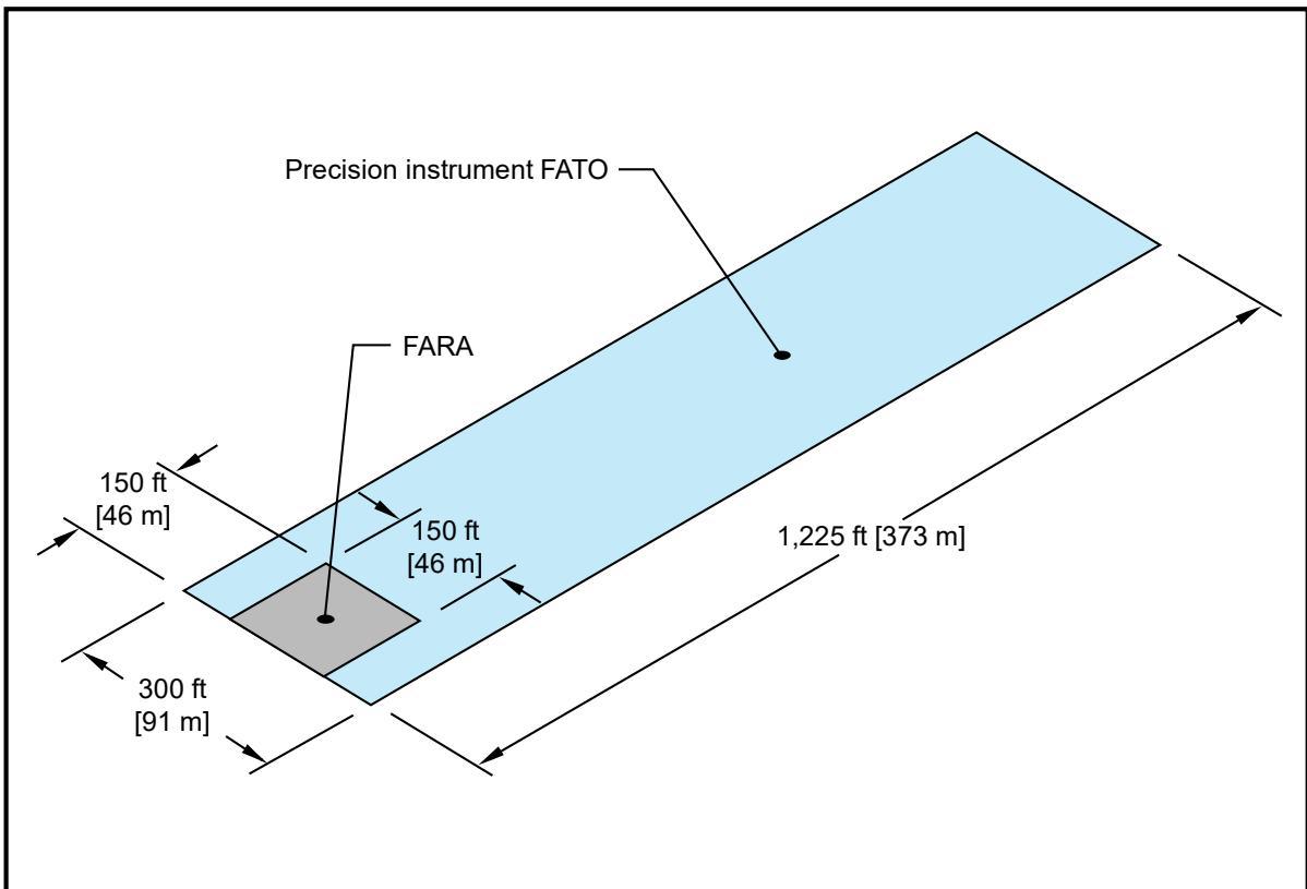
The illustrated FARA-FATO relationship is appropriate for a heliport located at an elevation up to 1,000 ft (305 m) above mean sea level.
6.5 Improved Instrument Lighting System.
The FAA has not established heliport lighting or helicopter approach lighting standards. Installing lighting systems similar to systems described below may result in lower visibility minimums. Coordinate these systems with Flight Standards and Air Traffic Control (ATC) for all low visibility operations. See Figure 6-2 and Figure 6-3.
6.5.1 FATO Perimeter Lighting Enhancement.
Insert an additional elevated green light meeting the standards of Appendix G between each light in the front and rear rows of the elevated perimeter lights to enhance the definition of the FATO.
6.5.2 Heliport Instrument Lighting System (HILS).
The HILS consists of 24 unidirectional PAR 56, 200-watt white lights that extend the FATO perimeter lights. The system extends both the right and left edge lights as edge bars and both the front and rear edge lights as wing bars, as shown in Figure 6-2.
6.5.2.1 Edge Bars.
Place edge bar lights at 50-foot (15.2 m) intervals, measured from the front and rear row of the FATO perimeter lights.
6.5.2.2 Elevated FATO Wing Bars.
Space wing bar lights at 15-foot (4.6 m) intervals, measured from the line of FATO perimeter (side) lights.
6.5.2.3 Optional TLOF Lights.
A line of seven white in-pavement lights meeting the standards of Appendix G is optional. Space the lights at 5-foot (1.5 m) intervals in the TLOF pavement. Align the lights on the centerline of the approach course to provide close-in directional guidance and improve TLOF surface definition. These lights are illustrated in Figure 6-2.
6.5.3 Heliport Approach Lighting System (HALS).
The HALS depicted in Figure 6-3 is a distinctive approach lighting configuration designed to prevent it from being mistaken for an airport runway approach lighting system.
Figure 6-2. Heliport Instrument Lighting System (HILS): Non-precision
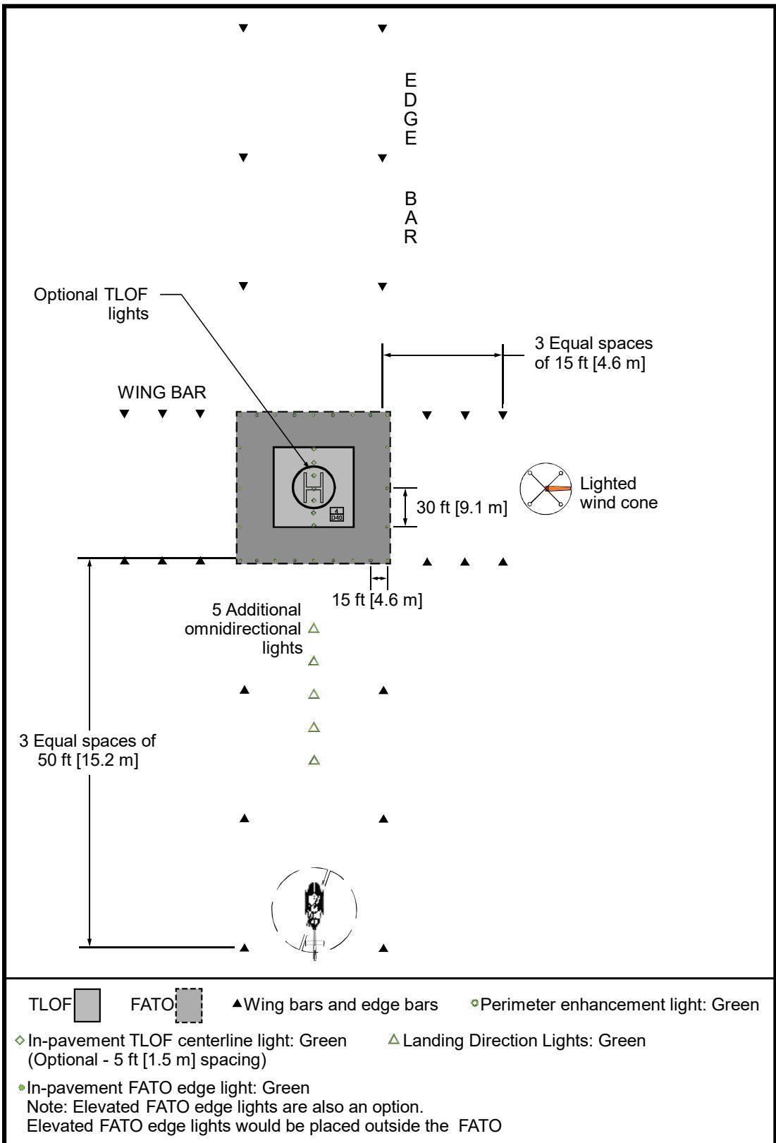
The illustrated HILS installation is appropriate for a minimally sized heliport at an elevation up to 1,000 ft (305 m) above MSL.
Figure 6-3. Heliport Approach Lighting System
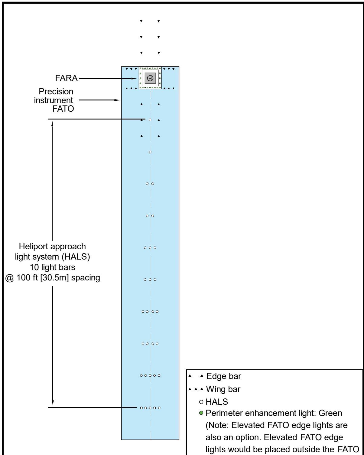
The illustrated heliport approach lighting system (HALS) relationship is appropriate for a heliport located at an elevation up to 1,000 ft (305 m) above mean sea level.
The illustrated HILS has elevated FATO edge lights. In-pavement FATO edge lights, which are also an option, would be placed just inside the FATO.
6.6 Obstacle Evaluation Surfaces.
The instrument procedure developer considers the specific heliport location, its physical characteristics, the terrain, surrounding obstructions, etc., in designing the helicopter instrument approach procedure. Upon development of the instrument procedure, protect the obstacle evaluation surfaces from penetrations. See paragraph 1.1 for additional guidance.
6.7 Visual Glideslope Indicators (VGSI).
A VGSI provides pilots with visual vertical course and descent cues. Install the VGSI such that the lowest on-course visual signal provides a minimum of one degree of clearance over any object that lies within ten degrees of the approach course centerline.
6.7.1 Siting.
The optimum location of a VGSI is on the extended centerline of the approach path at a distance that brings the helicopter to a hover with the undercarriage between 3 and 8 feet (0.9 to 2.4 m) above the TLOF.
See Figure 6-4 for an illustration of VGSI clearance criteria.
To properly locate the VGSI, estimate the vertical distance from the undercarriage to the pilot’s eye.
6.7.2 Control of the VGSI.
Design the VGSI to be pilot controllable such that it is “on” only when needed as an option.
6.7.3 VGSI Needed.
A VGSI is an optional feature. However, install a VGSI if one or more of the following conditions exist, especially at night:
Obstacle clearance, noise abatement, or traffic control procedures necessitate a slope to be flown.
The environment of the heliport provides few visual surface cues.
6.7.4 Additional Guidance.
Additional guidance is provided in AC 150/5345-52, Generic Visual Glideslope Indicators (GVGI), and AC 150/5345-28, Precision Approach Path Indicator (PAPI) Systems.
Figure 6-4. Visual Glideslope Indicator (VGSI) Siting and Clearance Criteria
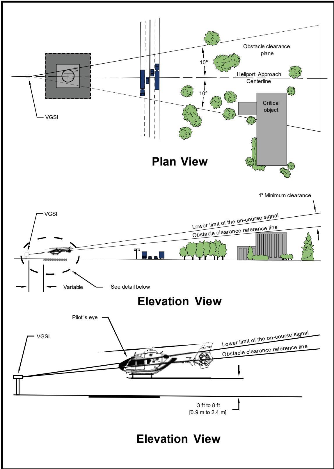
Page Intentionally Blank
CHAPTER 7. Heliport Site Safety Elements
7.1 General.
This chapter provides guidance on heliport site safety elements which provide enhanced safety for heliport operations.
7.2 Marking and Lighting of Difficult-To-See Objects.
Helicopter flight operations require maneuvering near the surface, where nearby obstacles can be a factor whether or not they actually penetrate any approach/departure or transitional surfaces. Objects such as poles, wires, and the high points of buildings are often difficult for a helicopter pilot to identify even in the best daylight conditions, making it difficult to take timely evasive action. Mark and light difficult-to-see objects near any approach/departure surface in accordance with the recommendations provided in AC 70/7460–1, Obstruction Marking and Lighting. Where it is not practical to mark or light an object (such as a tree), consider use of marked and lighted witness poles or low intensity solar obstruction lights.
7.2.1 Airspace.
Mark difficult-to-see objects to make them more conspicuous if they penetrate the applicable object identification surfaces, as illustrated in Figure 7-1 and Figure 7-2. Light difficult-to-see objects if a heliport supports operations between dusk and dawn. The object identification surfaces in these two figures are described as follows:
In all directions from the safety area, except under the approach/departure paths, the object identification surface starts at the safety area perimeter and extends out horizontally for 100 feet (30.5 m).
The object identification surface starts from the outside edge of the FATO and extends horizontally out for 800 feet (244 m) along the approach path under the approach/departure surface. The object identification surface extends out for an additional distance of 3,200 feet (975 m) along the approach path while rising on an 8:1 slope (8 units horizontal in 1 unit vertical) from this point. The object identification surface is 100 feet (30.5 m) beneath the approach/departure surface from the point 800 feet (244 m) from the FATO perimeter.
The width of this object identification surface under the approach/departure surface increases as a function of distance from the safety area. The object identification surface extends laterally to a point 100 feet (30.5 m) outside the safety area perimeter from the safety area perimeter. The object identification surface extends laterally 200 feet (61 m) on either side of the approach/departure path at the upper end of the surface.
Figure 7-1. Airspace Where Heliport Marking and Lighting are Recommended: Straight Approach
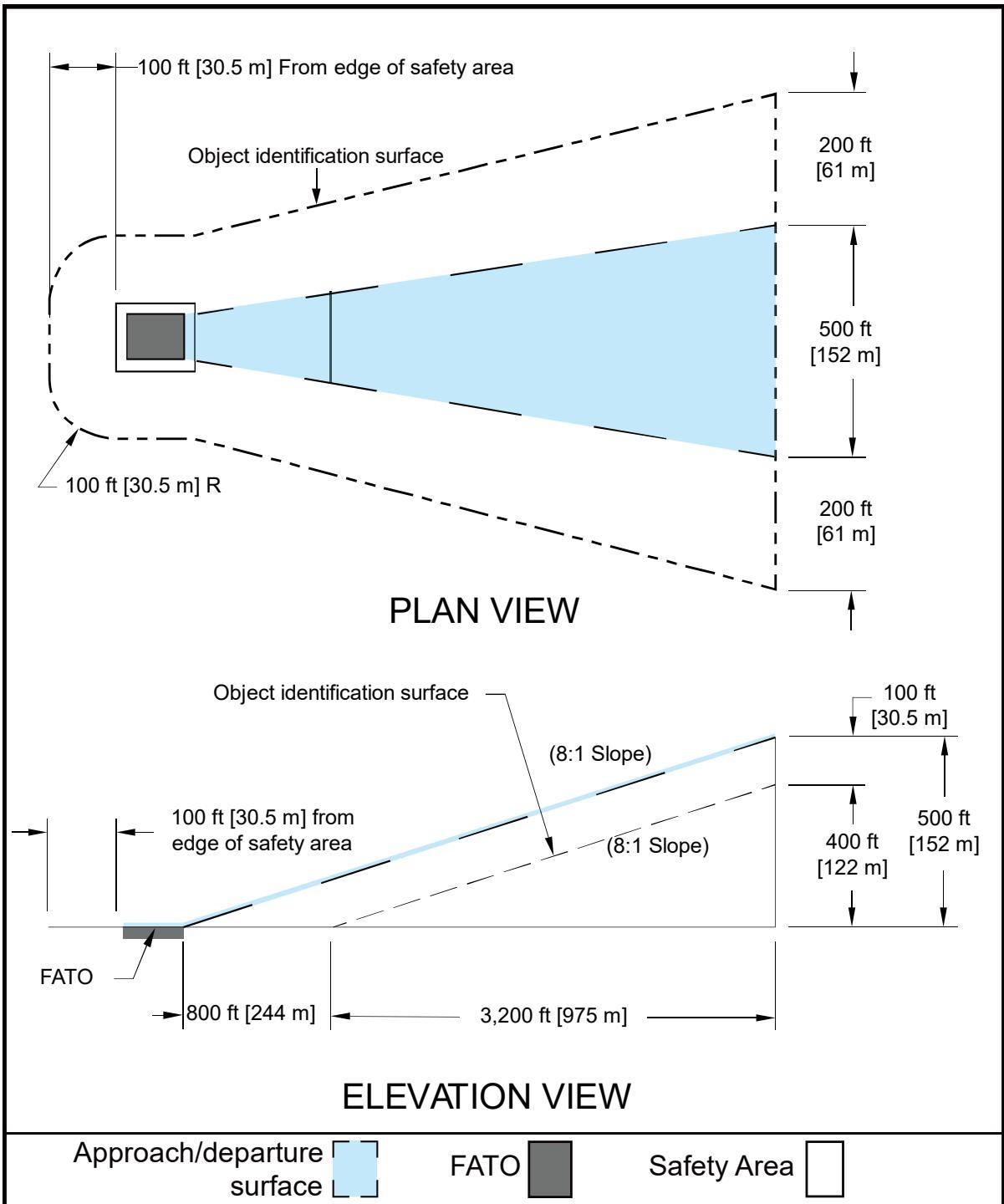
Figure 7-2. Airspace Where Heliport Marking and Lighting are Recommended: Curved Approach
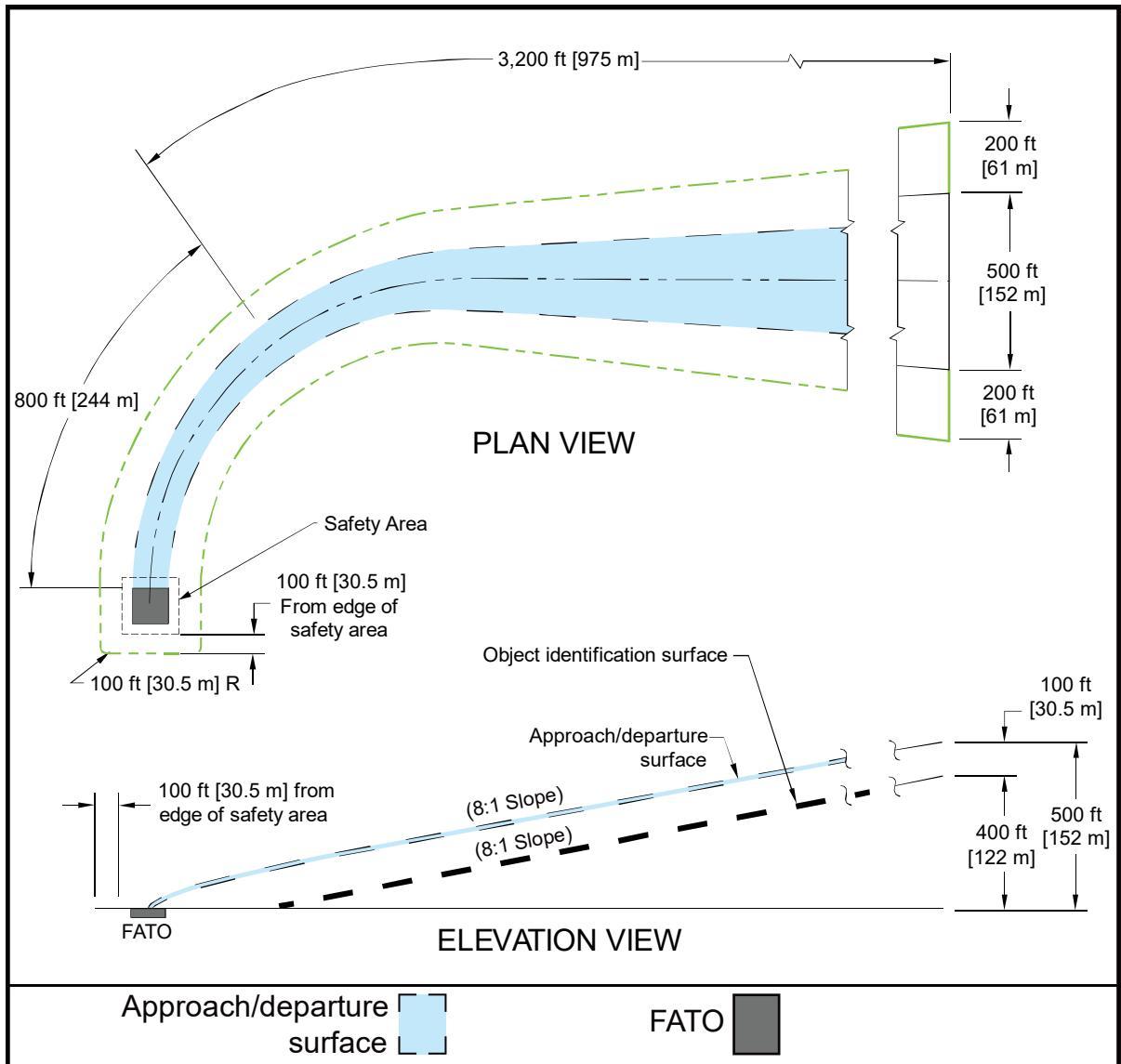
7.2.2 Shielding of Objects.
Section 77.9, Construction or Alteration Requiring Notice, provides that if there are several objects close together, it may not be necessary to mark all of them if they are shielded. Note that shielding does not apply to objects located on a public-use airport or heliport. Shielding applies only to off-airport objects.
To meet the shielding guidelines, Part 77 requires that an object “be shielded by existing structures of a permanent and substantial nature or by natural terrain or topographic features of equal or greater height and will be located in the congested area of a city, town, or settlement where the shielded structure will not adversely affect safety in air navigation.”
7.2.3 Equipment/Object Marking.
Make heliport maintenance and servicing equipment, as well as other objects used in the airside operational areas, conspicuous with paint, reflective paint, reflective tape, or other reflective markings. Reference AC 150/5210-5, Painting, Marking, and Lighting of Vehicles Used on an Airport.
7.3 Safety Considerations.
Consider the following safety enhancements in the design of a heliport, as described below. Address other areas, such as the effects of rotor downwash, based on site conditions and the design helicopter.
7.3.1 Security.
Provide a heliport with the appropriate means of keeping the operational areas clear of people, animals, and vehicles. Use a method to control access depending upon the helicopter location, type of operation, and types of potential intruders. Follow the guidelines below for use of safety barriers and access control measures:
For ground-level heliports, erect a safety barrier around the helicopter operational areas in the form of a fence or a wall. Other types of safety barriers may be used if they provide adequate positive deterrent to persons inadvertently entering an operational area.
Construct the safety barrier outside of the safety area and below the elevation of the approach/departure and transitional surfaces.
If necessary, near the approach/departure paths, install the barrier well outside the outer perimeter of the safety area.
Ensure any safety barrier is high enough to present a positive deterrent to persons inadvertently entering an operational area but low enough to be non-hazardous to helicopter operations. If the barrier is located under the approach/departure surface, consider lighting the barrier for enhanced visibility for pilots.
For TRANSPORT heliports, control access to airside areas with adequate security measures.
For GENERAL AVIATION and HOSPITAL heliports, control access to airside areas in a manner commensurate with the barrier (for example, build fences with locked gates).
Display a heliport caution sign similar to that shown in Figure 7-3 at all access points.
As an option at HOSPITAL heliports, secure operational areas via the use of security guards and a mixture of fixed and movable barriers.
Figure 7-3. Heliport Caution Sign
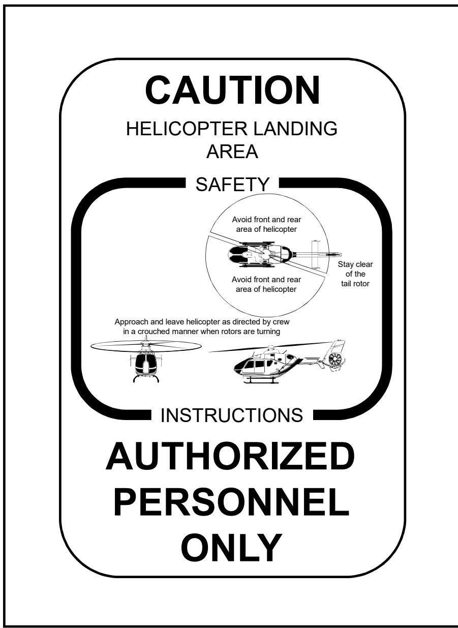
7.3.2 Rescue and Fire Fighting Services.
Heliports are subject to state and local rescue and fire fighting regulations. Provide a fire hose cabinet or extinguisher at each access gate/door and each fueling location. Locate fire hose cabinets, fire extinguishers, and other fire fighting equipment adjacent to, but below the level of, the TLOF (and below the level of the FATO for elevated FATOs at TRANSPORT heliports). See additional guidance in NFPA publications listed in Appendix E.
7.3.3 Communications.
Use a Common Traffic Advisory Frequency (CTAF) radio to provide arriving helicopters with heliport and traffic advisory information but do not use this radio to
control air traffic. Contact the Federal Communications Commission (FCC) for information on CTAF licensing.
7.3.4 Weather Information.
An automated weather observing system (AWOS) measures and automatically broadcasts current weather conditions at the heliport site. When installing an AWOS, locate it at least 100 feet (30.5 m) and not more than 700 feet (213 m) from the TLOF and such that its instruments will not be affected by rotor wash from helicopter operations. Find guidance on AWOS systems in AC 150/5220-16, Automated Weather Observing Systems (AWOS) for Non-Federal Applications, and FAA Order 6560.20, Siting Criteria for Automated Weather Observing Systems (AWOS). Other weather observing systems will have different siting criteria.
7.3.5 Winter Operations.
Swirling snow dispersed by a helicopter’s rotor wash can cause the pilot to lose sight of the intended landing point and/or hide objects that need to be avoided.
Design the heliport to accommodate the methods and equipment to be used for snow removal.
Design the heliport to allow the snow to be removed sufficiently so it will not present an obstruction hazard to the tail rotor, main rotor, or undercarriage.
For heliports subject to winter weather and ice/snow, an optional dark TLOF surface can be used to absorb more heat from the sun and melt residual ice and snow. See paragraph 4.3.4 for guidance on markings for winter operations.
Find guidance on winter operations in AC 150/5200-30, Airport Field Condition Assessments and Winter Operations Safety.
APPENDIX A. EMERGENCY HELICOPTER LANDING FACILITIES (EHLF)
A.1 General.
Preplanning emergency landing areas will result in safer and more effective air-support operations. These facilities comprise rooftop emergency facilities and medical emergency sites and are not for routine helicopter operations. Use the following as a guide for developing EHLF facilities.
A.2 Notification and Coordination.
In addition to any requirements to provide notice under Part 157, advise the local Terminal Approach Radar Control or the local ATC facility manager in writing of the EHLF.
A.3 Rooftop Emergency Facilities.
Review local building codes to determine if they require structures over a specified height to provide a clear area on the roof capable of accommodating a helicopter to facilitate fire fighting or emergency evacuation operations.
A.3.1 Building Code Requirements.
State and local building code requirements apply to rooftop facilities. Develop the landing surface to the local fire department requirements based on the size and weight of the helicopter(s) expected to engage in fire or rescue operations (see Figure A-1). Find additional information in various NFPA publications. For additional reference material, see Appendix E.
A.3.2 TLOF.
Design the TLOF per the following guidelines:
A.3.2.1 Size. Design the TLOF to be square, rectangular, or circular in configuration and centered within the EHLF. Design the length and width or diameter to be at least the controlling dimension D of the largest aircraft expected to use the EHLF.
A.3.2.2 Weight Capacity. Design the TLOF to accommodate the maximum takeoff weight of the design helicopter expected to use the EHLF.
A.3.2.3 Access. Provide two pedestrian access points to the TLOF at least 90 degrees apart with a minimum of 60 feet (18.3 m) TLOF perimeter separation.
A.3.2.4 Drainage.
Design the surface so drainage flows away from pedestrian access points, with a maximum slope of 1.5 to 2.0 percent.
Figure A-1. Rooftop Emergency Landing Facility
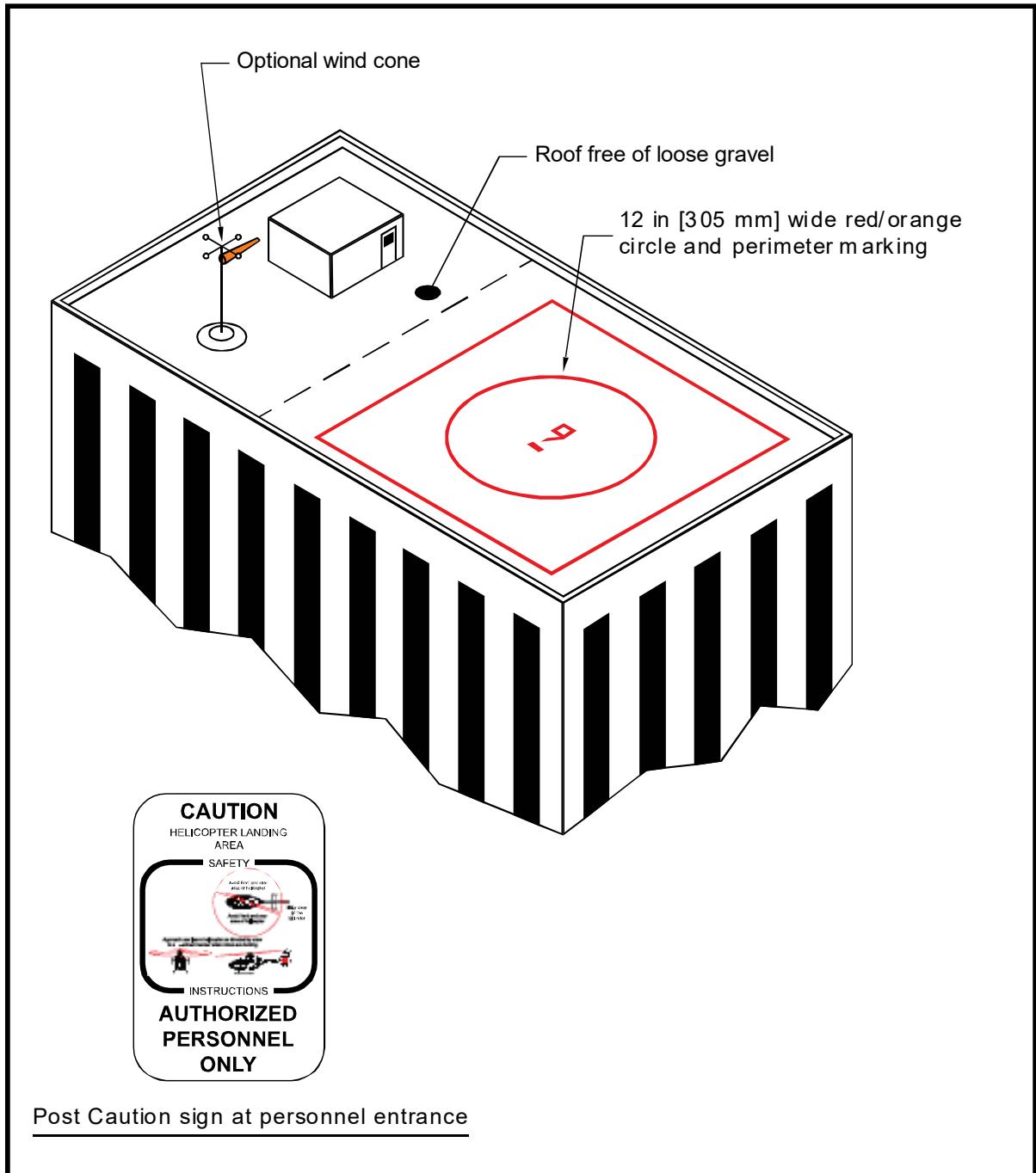
The example shown in the illustration indicates a 9,000 lb (4,082 kg) weight limitation in the center of circle.
A.3.3 FATO.
Design the FATO to be at the same level as the TLOF.
A.3.3.1 Size.
Design the FATO to extend a distance of at least 45 feet (13.7 m) in all directions from the center of the EHLF. For safe operation, provide clearance of 0.28 D of the largest helicopter expected but not less than 20 feet (6.1 m) between the helicopter’s main and tail rotor blades and any object that could be struck by these blades.
A.3.3.2 Obstructions.
As an option, design the FATO to be an imaginary surface outside the TLOF and extending beyond the structure edge. Design the FATO to be unobstructed and without penetration of obstacles such as parapets, window washing equipment, penthouses, handrails, antennas, vents, etc.
A.3.4 Safety Area.
Provide a clear, unobstructed area, a minimum of 12 feet (3.7 m) wide, on all sides, outside and adjacent to the FATO.
A.3.5 Safety Net.
If the platform is elevated 4 feet (1.2 m) or more above its surroundings, 29 CFR Section 1910.23, Duty to Have Fall Protection and Falling Object Protection, requires the provision of fall protection. The FAA recommends such protection for all platforms elevated 30 inches (0.8 m) or more. However, do not use permanent railings or fences since they would be safety hazards during helicopter operations. As an option, install a safety net, meeting state and local regulations, but not less than 5 feet (1.5 m) wide. Design the safety net to have a load carrying capability of 25 lbs/sq ft (122 kg/sq m). The net does not project above the level of the TLOF. Fasten both the inside and outside edges of the safety net to a solid structure. Construct nets of materials that are resistant to environmental effects.
A.3.6 Markings.
A.3.6.1 TLOF Perimeter.
A.3.6.2 Touchdown/Positioning Circle (TDPC) Marking.
Center a 12-inch (0.3 m) wide red or orange circular marking, 30 feet (9.1 m) in diameter, within the TLOF. Use a contrasting color for the background within the circle.
A.3.6.3 Weight Capacity.
Mark the TLOF with the maximum takeoff weight of the design helicopter, in units of thousands of pounds (for example, a number “9”
indicating 9,000 lbs (4,082 kg) GW), with each numeral ten feet (3 m) in height, centered within the TLOF.
A.3.6.4 Markings for Pedestrians.
Clearly mark rooftop access paths, EHLF access paths, and assembly zone(s) with surface paint and instructional signage.
A.3.7 Access.
A.3.7.1 Stairs.
Provide a minimum of two rooftop access stairs, with no less than 150 degrees separation, connecting to the top floor of the structure, with at least one providing access to the structure’s emergency staircase.
A.3.7.2 Doors.
Always keep the penthouse and stairwell rooftop access doors unlocked to provide access to the EHLF. As an option, equip doors with “panic bar” hardware and/or alarm them.
A.3.8 Wind Cone.
Install a wind cone assembly conforming to AC 150/5345-27 to show the direction and magnitude of the wind. Ensure it is an orange wind cone within the line-of-sight from the EHLF and outside the approach/departure path(s).
A.3.9 Lighting.
Shield ambient rooftop lighting to avoid affecting the pilot’s vision.
APPENDIX B. PRE-DESIGNATED EMERGENCY LANDING AREAS (PELAS)
Pre-designated emergency landing areas (PELAs) are clear and level areas near the scene of an accident or incident that the local emergency response team designates as the place where the helicopter air ambulance is directed to land to transport an injured person to a hospital. Provide such sites in various locations within a jurisdiction to support fast response to medical emergencies and accidents. Pre-designating these areas provides the opportunity to inspect potential sites in advance and to select sites that have adequate clear approach/departure airspace and adequate clear ground space. See the Aeronautical Information Manual (AIM), Chapter 10, for guidance on setting up offsite scene or PELA landing sites.
Page Intentionally Blank
APPENDIX C. HELICOPTER DATA
This appendix contains selected helicopter data needed by a heliport designer. These data represent the most critical weight, dimensional, or other data entry for that helicopter model, recognizing that specific versions of the model may weigh less, be smaller in some features, carry fewer passengers, etc.
Various helicopter manufacturers have provided this information. Confirm data by contacting the manufacturer(s) of the specific helicopter(s) of interest.
Legend for Figure C-1 and Table C-1: Helicopter Dimensions and Data
| A | Manufacturer name and helicopter model |
| B | Maximum takeoff weight in pounds |
| D | Controlling dimension |
| E | Number of blades |
| F | Rotor plane clearance in feet |
| H | Overall height in feet (usually at tail rotor) |
| I | Tail rotor diameter (in feet) |
| J | Number of tail rotor blades |
| K | Tail rotor ground clearance in feet |
| L | Type of undercarriage |
| M | Number and type of engines |
| N | Number of crew and passengers |
| OL | Overall helicopter length in feet (rotors at their maximum extension) |
| oW | Overall aircraft width in feet |
| RD | Rotor diameter in feet |
| TR | Distance from rotor hub to tip of tail rotor in feet |
| UCL | Undercarriage length in feet |
| UCW | Undercarriage width in feet (the distance between the outside edges ofthe tires or the skids) |
Figure C-1. Helicopter Dimensions
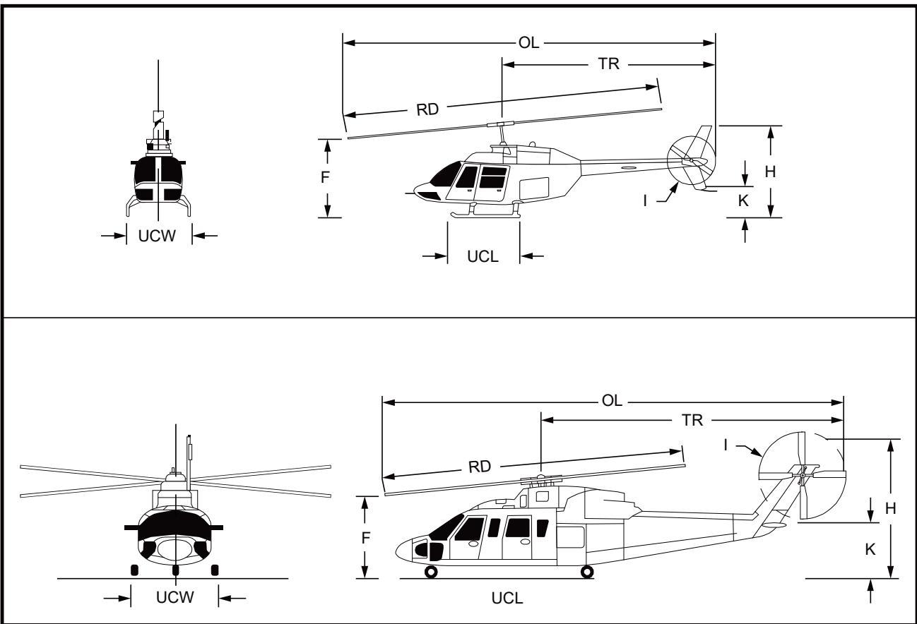
Table C-1. Helicopter Data
| Manufacturer/Model | M HoayeL unuxeN | (4}) uojsuug uo.uo | (H) uuT Ie.AO | () u!H IR.AO | Main Rotor | Tail Rotor | Undercarriage | /su3ug Jo JaqunNadL | /.0qunN Ma.DJaqunN xed | |||||||
| (H) Jauna | sopeia Jo aqunN | E pun0.15 | (H) sn!pey | (H) .uRa | sapeia Jo aqunN | 田puno. | adKI | () q8uT | () up!M | |||||||
| A | B | D | OL | H | RD | E | F | TR | I | J | K | L | UCL | UCW | M | N |
| AgustaWestland | ||||||||||||||||
| A-109A | 5,732 | 42.8 | 42.8 | 11.2 | 36.1 | 4 | 10 | 25 | 6.7 | 2 | 2.3 | wheel | 11.6 | 7.5 | 2-T | 1-2&6-7 |
| A-119 Koala | 5,997 | 42.7 | 42.7 | 12.4 | 36.6 | 4 | 8.3 | 25.5 | 6.4 | 2 | 4.2 | skid | 13.4 | 5.5 | 1-T | 1&6-7 |
| AW-109E Power | 6,283 | 42.8 | 42.8 | 11.5 | 36.1 | 4 | 8 | 6.4 | 2 | 3 | wheel | 11.5 | 7.1 | 2-T | 187 | |
| AW-109S Grand | 7,000 | 42.5 | 42.5 | 11.2 | 35.5 | 4 | 8 | 6.4 | 2 | 3.3 | wheel | 12.3 | 7.1 | 2-T | 1-2&6-7 | |
| AW-119 Ke | 6,283 | 42.4 | 42.4 | 11.8 | 35.5 | 4 | 9.3 | 6.4 | 2 | 3.8 | skid | 11.1 | 7 | 1-T | 186-7 | |
| AW-139 | 14,991 | 54.7 | 54.7 | 16.4 | 42.6 | 5 | 12.9 | 8.9 | 4 | 7.5 | wheel | 14.2 | 10 | 2-T | 1-28&15 | |
| AW-101 | 34,392 | 74.8 | 74.8 | 21.7 | 61 | 5 | 15.4 | 45 | 13.1 | 8.4 | wheel | 23 | 14.8 | 3-T | 3&30 | |
| Westland WG30 | 12,800 | 52.2 | 52.2 | 15.5 | 43.7 | 4 | 12.5 | 31 | 8 | 4 | 7.5 | wheel | 17.9 | 10.1 | 2+T | 2&19 |
| Bell Helicopter | ||||||||||||||||
| 47G | 2,950 | 43.6 | 43.6 | 9.3 | 37.1 | 2 | 5 | 25 | 6.1 | 2 | 3.5 | skid | 9.9 | 7.5 | 1-P | 182-3 |
| 205B, UH-1H,Huey I, 210 | 10,500 | 57.8 | 57.8 | 14.5 | 48 | 2 | 7.3 | 33.1 | 8.5 | 2 | 5.9 | skid | 12.1 | 8.8 | 1-T | 1&14 |
| 206B-1,2,3 | 3,350 | 39.2 | 39.2 | 10.8 | 33.4 | 2 | 6 | 22.5 | 5.2 | 2 | 2.1 | skid | 8.1 | 6.7 | 1-T | 1&4 |
| 206L-1,3,4 | 4,450 | 42.4 | 42.4 | 10.9 | 37 | 2 | 6.4 | 24 | 5.4 | 2 | 3.5 | skid | 9.9 | 7.7 | 1-T | 186 |
| 212 | 11,200 | 57.3 | 57.3 | 14.9 | 48.2 | 2 | 7.5 | 22.2 | 8.5 | 2 | 6.1 | skid | 12.1 | 8.8 | 2-T | 1814 |
| 214ST | 17,500 | 62.2 | 62.2 | 15.9 | 52 | 2 | 6.5 | 37 | 9.7 | 2 | 3.5 | wheel/skid | 12.1 | 8.6 | 2-T | 2&16-17 |
| 222B,UT | 8,250 | 50.3 | 50.3 | 12.2 | 42 | 2 | 9.2 | 29.2 | 6.9 | 2 | 2.7 | wheel/skid | 12.2 | 7.8 | 2-T | 1&9 |
| 230 | 8,400 | 50.3 | 50.3 | 11.7 | 42 | 2 | 9.2 | 29.2 | 6.9 | 2 | 2.7 | whee/skid | 12.2 | 7.8 | 2-T | 1&9 |
| 407 | 5,250 | 41.4 | 41.4 | 10.2 | 35 | 4 | 7.8 | 24.3 | 5.4 | 2 | 3.2 | skid | 9.9 | 8.1 | 1-T | 1&6 |
| 412EP, SP, HP | 11,900 | 56.2 | 56.2 | 14.9 | 46 | 4 | 11.5 | 34 | 8.6 | 2 | 4.8 | skid | 12.1 | 9.5 | 2-T | 1&14 |
| 427VFR | 6.,550 | 42.6 | 42.6 | 10.5 | 37 | 4 | 6.4 | 24.1 | 5.7 | 2 | 3.3 | skid | 10 | 8.3 | 2-T | 1&7 |
| 429 | 7,000 | 43 | 43 | 13.3 | 36 | 4 | 8.5 | 5.4 | 2 | 3.5 | skid | 9.9 | 8.8 | 2-T | 187 | |
| 430 | 9,300 | 50.3 | 50.3 | 13.3 | 42 | 4 | 8.2 | 29.2 | 6.9 | 2 | 3.7 | wheel/skid | 12.4 | 9.2 | 2-T | 1&9 |
Appendix C
| Manufacturer/Model | uM HoayeL unxe | (4) uoisuna Suo.u | (4) y8uT I.1AO | (H) u8!H IE.1AO | Main Rotor | Tail Rotor | Undercarriage | /sau8ug Jo .IqunNadkL | /aqunN MaD.aqunN xed | |||||||
| (H) na | sopeia Jo JaqunN | ea puno.5() | () snipey | (H) 1guer!a | sop ia Jo .aqunN | ue.ean puno.5四 | adKL | (4) u8uaT | () up!M | |||||||
| A | B | D | OL | H | RD | E | F | TR | I | J | K | L | UCL | UCW | M | N |
| Boeing | ||||||||||||||||
| 107/CH-46E | 24,300 | 84.3 | 84.3 | 16.7 | 51 | 3 | 15 | 59 | 51 | 3 | 17 | wheel | 24.9 | 14.5 | 2-T | 3&25 |
| 234/CH-47F/G | 54,000 | 99 | 99 | 19 | 60 | 3 | 11 | 69 | 60 | 3 | 19 | wheel | 22.5 | 10.5 | 2-T | 3&44 |
| Brantly/Hynes | ||||||||||||||||
| B-2B | 1,670 | 28.1 | 28.1 | 6.9 | 23.8 | 3 | 4.8 | 16 | 4.3 | 2 | 3 | skid | 7.5 | 6.8 | 1-P | 1&1 |
| 305 | 2,900 | 32.9 | 32.9 | 8.1 | 28.7 | 3 | 8 | 19 | 4.3 | 2 | 3 | wheel/skid | 6.2 | 6.8 | 1-P | 1&4 |
| Enstrom | ||||||||||||||||
| F-28F/280FX | 2,600 | 29.3 | 29.3 | 9 | 32 | 3 | 6 | 20.6 | 4.7 | 2 | 3.1 | skid | 8 | 7.3 | 1-P | 1&2 |
| 480B/TH-28 | 3,000 | 30.1 | 30.1 | 9.7 | 32 | 3 | 6.5 | 21.2 | 5 | 2 | 3.6 | skid | 9.2 | 8 | 1-T | 1&4 |
| Erickson | ||||||||||||||||
| S-64E/F AirCrane | 42,000-4700 | 88.5 | 88.5 | 25.4 | 72 | 6 | 15.7 | 53 | 16 | 4 | 9.4 | wheel | 24.4 | 19.9 | 2-T | 3&0 |
| Eurocopter | ||||||||||||||||
| SA-315 Lama | 5,070 | 42.3 | 42.3 | 10.2 | 36.2 | 3 | 10.1 | 20 | 6.3 | 3 | 3.2 | skid | 10.8 | 7.8 | 1-T | 184 |
| SA-316/319Alouette | 4,850 | 33.4 | 33.4 | 9.7 | 36.1 | 3 | 9.8 | 27.7 | 6.3 | 3 | 2.8 | wheel | 11.5 | 8.5 | 1-T | 1&4 |
| SA-330 Puma | 16,315 | 59.6 | 59.6 | 16.9 | 49.5 | 4 | 14.4 | 35 | 10 | 5 | 6 | wheel | 13.3 | 9.8 | 2-T | 2&20 |
| SA/AS-332, SuperPuma | 20,172 | 61.3 | 61.3 | 16.3 | 53.1 | 4 | 14.6 | 36 | 10 | 5 | 7.1 | wheel | 17.3 | 9.8 | 2-T | 2&24 |
| SA-341/342Gazelle | 4,100 | 39.3 | 39.3 | 10.2 | 34.5 | 3 | 8.9 | 23 | Fenestron | 2.4 | skid | 6.4 | 6.6 | 1-T | 1&4 | |
| AS-350 A Star | 4,960 | 42.5 | 42.5 | 11 | 35.1 | 3 | 10.6 | 25 | 6.1 | 2 | 2.3 | skid | 4.7 | 7.5 | 1-T | 1&6 |
| AS-355 Twin Star | 5,732 | 42.5 | 42.5 | 9.9 | 35.9 | 3 | 10.3 | 25 | 6.1 | 2 | 2.3 | skid | 9.6 | 7.1 | 2-T | 1&6 |
| AS-360 Dauphin | 6,600 | 43.3 | 43.3 | 11.5 | 37.7 | 4 | 10.7 | 25 | Fenestron | 2.6 | wheel | 23.7 | 6.4 | 1-T | 1&13 | |
| AS-365Dauphin/H-65Dolphin | 9,480 | 45.1 | 45.1 | 13.3 | 39.2 | 4 | 11.4 | 24 | Fenestron | 2.6 | wheel | 11.9 | 6.2 | 2-T | 1&11 | |
| BO-105 | 5,732 | 38.9 | 38.9 | 11.5 | 32.3 | 4 | 9.8 | 23 | 6.2 | 2 | 6.1 | skid | 8.3 | 8.2 | 2-T | 1&5 |
| BK-117 | 7,385 | 42.7 | 42.7 | 12.6 | 36.1 | 4 | 11 | 25 | 6.4 | 2 | 6.3 | skid | 11.6 | 8.2 | 2-T | 1&10 |
| EC-120 | 3,780 | 37.8 | 37.8 | 11.2 | 32.8 | 3 | 10.1 | 24.6 | Fenestron | 2.1 | skid | 9.4 | 6.8 | 1-T | 1&4 | |
| EC-130 | 5,291 | 41.5 | 41.5 | 11.8 | 35.1 | 3 | 11 | 23.7 | Fenestron | 5.3 | skid | 10.5 | 7.9 | 1-T | 1&7 | |
Appendix C
| Manufacturer/Model | M HoL un | (4) uoisuna Suo.u | (4) q8uT I.1AO | (H) u !H IE.IAO | Main Rotor | Tail Rotor | Undercarriage | /sou3ug Jo qunNadkL | /aqunN MaDJaqunN xed | |||||||
| (H) Jea | sapeia jo .squnN | uean pno.15(4) | () snpe | (H) spuer | sapea o aqunn | e puonm | adsI | (4}) qöuaT | () up!M | |||||||
| A | B | D | OL | H | RD | E | F | TR | I | J | K | L | UCL | UCW | M | N |
| EC-135 | 6,250 | 40 | 40 | 11.5 | 33.5 | 4 | 11 | 22.8 | Fenestron | 5.6 | skid | 10.5 | 6.6 | 2-T | 1&6 | |
| EC-145/UH-72A | 7,904 | 42.7 | 42.7 | 13 | 36.1 | 4 | 11.3 | 28 | 6.4 | 2 | 10.7 | skid | 9.5 | 7.9 | 2-T | 1&8 |
| EC-155 | 10,692 | 46.9 | 46.9 | 14.27 | 41.3 | 5 | 12 | 23 | Fenestron | 3.1 | wheel | 12.8 | 6.2 | 2-T | 2812 | |
| EC-225 | 24,332 | 64 | 64 | 16.3 | 53.1 | 5 | 15.1 | 38 | 10.3 | 4 | 3.5 | wheel | 17.2 | 9.8 | 2-T | 2824 |
| Kaman | ||||||||||||||||
| K-Max/K1200 | 7,000 | 52 | 52 | 21 | 48.2 | 4 | 10.7 | 28 | n | a | n/a | wheel | 15.3 | 11.3 | 1-T | 1&0 |
| SH-2G Seasprite | 14,200d | 52.5 | 52.5 | 15.1 | 44 | 4 | 8.1 | 4 | wheel | 2-T | 388 | |||||
| MD Helicopters | ||||||||||||||||
| 500E | 3,000 | 30.8 | 30.8 | 8.4 | 26.4 | 5 | 8.2 | 4.6 | 2 | 2 | skid | 8.1 | 6.3 | 1-T | 184 | |
| 530F | 3,100 | 32.1 | 32.1 | 8.1 | 27.4 | 5 | 8 | 19 | 4.8 | 2 | 1.3 | skid | 8.1 | 6.4 | 1-T | 1&4 |
| 520N | 3,350 | 32.1 | 32.1 | 9.7 | 27.4 | 5 | 9.2 | 17 | NOTAR | n/a | skid | 8.1 | 6.3 | 1-T | 1&4 | |
| 600N | 4,100 | 36.9 | 36.9 | 9.8 | 27.5 | 6 | 9.2 | NOTAR | n/a | skid | 10.1 | 8.8 | 1-T | 1&7 | ||
| Explorer/ 902 | 6,500 | 38.8 | 38.8 | 12 | 33.8 | 5 | 12 | 23 | NOTAR | n/a | skid | 7.3 | 7.3 | 2-T | 1-2&6-7 | |
| Robinson | ||||||||||||||||
| R-22 Beta | 1,370 | 28.8 | 28.8 | 8.9 | 25.2 | 2 | 8.8 | 16 | 3.5 | 2 | 4.1 | skid | 4.2 | 6.3 | 1-P | 181 |
| R-44 Raven | 2,500 | 38.3 | 38.3 | 10.8 | 33 | 2 | 10.5 | 22 | 4.8 | 2 | 3.8 | skid | 4.2 | 7.2 | 1-P | 1&3 |
| R-66 Turbine | 2,700 | 38.3 | 38.3 | 11.4 | 33 | 2 | 10.5 | 5 | 2 | 3.6 | skid | 4.2 | 7.5 | 1-T | 1&4 | |
| Fairchild-Hiller/Rogerson-Hiller | ||||||||||||||||
| 360/UH-12/OH-23 | 3,100 | 40.8 | 40.8 | 10.2 | 35.4 | 2 | 10.1 | 23 | 6 | 2 | 4 | skid | 8.3 | 7.5 | 1-P | 1&3 |
| FH/RH-1100 | 3,500 | 41.3 | 41.3 | 9.2 | 35.3 | 2 | 9.5 | 24 | 6 | 2 | 3 | skid | 7.9 | 7.2 | 1-T | 1&4 |
| Sikorsky/Schweizer | ||||||||||||||||
| HU-269A/A-1/B,TH55A | 1,850 | 29 | 29 | 9 | 26 | 3 | 8.8 | 15 | 3.8 | 2 | 2.5 | skid | 8.3 | 6.5 | 1-P | 1&1 |
| 300C | 2,050 | 30.8 | 30.8 | 8.7 | 26.8 | 3 | 8.7 | 15.3 | 4.3 | 2 | 2.8 | skid | 8.3 | 6.5 | 1-P | 1&2 |
| 300CB/CBi | 1,750 | 30.8 | 30.8 | 8.7 | 26.8 | 3 | 8.7 | 15.3 | 4.3 | 2 | 2.8 | skid | 8.3 | 6.5 | 1-P | 1&1 |
| 330/330SP/333 | 2,550 | 31.2 | 31.2 | 11 | 27.5 | 3 | 9.2 | 15.3 | 4.3 | 2 | 3.2 | skid | 8.3 | 6.5 | 1-T | 182-3 |
| S-434 | 2,900 | 31.2 | 31.2 | 11 | 27.5 | 4 | 9.2 | 15.3 | 4.3 | 2 | 3.2 | skid | 8.3 | 6.5 | 1-T | 182-3 |
Appendix C
| Manufacturer/Model | a HoayeL unuxen | (4) uoisua uou | () uuT IAO | (H) I.AO | Main Rotor | Tail Rotor | Undercarriage | /sou3ua J0 NqunNadkL | /.3qunN ma.DJaqunN xed | |||||||
| (H) Jwna | sapeia o aqunN | aee puno国 | () snipey | () .Iuea | sapeia o aqunn | ueeaiS puno.s国 | adKI | (4) up8uaT | () uP!M | |||||||
| A | B | D | OL | H | RD | E | F | TR | I | J | K | L | UCL | UCW | M | N |
| S-55/H19 | 7,900 | 62.6 | 62.6 | 13.1 | 53 | 3 | 8.2 | 2 | wheel | 1-T | 2&12 | |||||
| S-58/H34 | 14,600 | 65.8 | 65.8 | 15.9 | 56 | 4 | 11.4 | 38 | 9.5 | 4 | 6.4 | wheel | 28.3 | 14 | 2-T | 2&16 |
| S-61/H-3 | 22,000 | 72.8 | 72.8 | 19 | 62 | 5 | 12.3 | 40 | 10.3 | 5 | 8.6 | wheel | 23.5 | 14 | 2-T | 3&28 |
| S-76A/B/C/D | 11,700 | 52.5 | 52.5 | 14.6 | 44 | 4 | 8.2 | 30.5 | 8 | 4 | 6.5 | wheel | 16.4 | 8 | 2-T | 2&12 |
| S-92 | 26,500 | 68.5 | 68.5 | 17.9 | 56.3 | 4 | 9.8 | 39.9 | 11 | 4 | 6.9 | wheel | 20.3 | 10.4 | 2-T | 2&19 |
| S-70i/UH-60LBlackhawk | 22,000 | 64.8 | 64.8 | 16.8 | 53.8 | 4 | 7.7 | 38 | 11 | 4 | 6.6 | wheel | 29 | 9.7 | 2-T | 3&12 |
| CH-53K | 74,000 | 99.5 | 99.5 | 27.8 | 79 | 7 | 17 | 59.6 | 20 | 4 | 9.5 | wheel | 27.3 | 13 | 3-T | 3&55 |
APPENDIX D. DIMENSIONS FOR MARKING SIZE AND WEIGHT LIMITATIONS
The form and proportion of numbers and letters for marking TLOF and parking area size and weight limitations are shown in the two figures below for both 36-inch (0.9 m) and 18-inch (0.5 m) numbers.
Figure D-1. Form and Proportions of 36-inch (0.9 m) Numbers for Marking Size and Weight Limitations
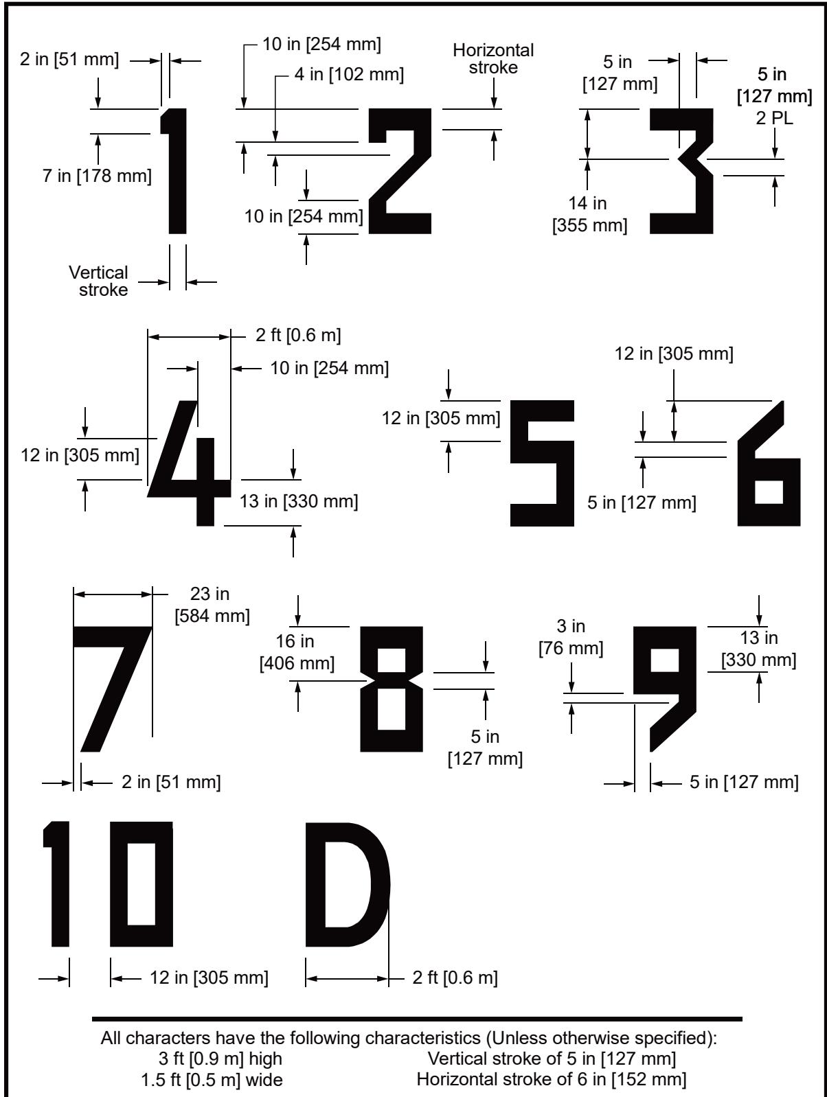
Figure D-2. Form and Proportions of 18-inch (0.5 m) Numbers for Marking Size and Weight Limitation
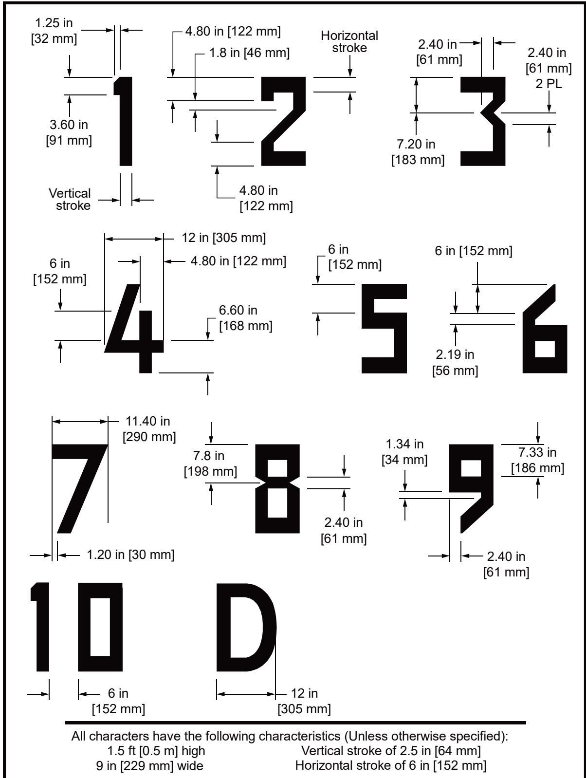
Page Intentionally Blank
APPENDIX E. ASSOCIATED PUBLICATIONS AND RESOURCES
The following is a listing of related documents and resources:
E.1 Current Electronic Code of Federal Regulations (e-CFRs) are available from the Government Printing Office website https://www.ecfr.gov/.
14 CFR Part 27 Airworthiness Standards: Normal Category Rotorcraft
14 CFR Part 29 Airworthiness Standards: Transport Category Rotorcraft
14 CFR Part 77 Safe, Efficient Use, and Preservation of the Navigable Airspace
14 CFR Part 91 General Operating and Flight Rules
14 CFR Part 121 Air Carrier Certification
14 CFR Part 135 Operating Requirements: Commuter and on demand operations and rules governing persons on board such aircraft
14 CFR Part 139 Certification of Airports
14 CFR Part 151 Federal Aid to Airports
14 CFR Part 152 Airport Aid Program
14 CFR Part 157 Notice of Construction, Alteration, Activation, and Deactivation of Airports
29 CFR Part 1910 Occupational Safety and Health Standards
29 CFR Part 1926 Safety and Health Regulations for Construction
E.2 Airport Advisory Circulars are available at the Airports website https://faa.gov/airports/resources/advisory_circulars/.
AC 70/7460-1 Obstruction Marking and Lighting
AC 150/5020-1 Noise Control and Compatibility Planning for Airports
AC 150/5190-4 A Model Zoning Ordinance to Limit Height of Objects Around Airports
AC 150/5200-30 Airport Field Condition Assessments and Winter Operations Safety
AC 150/5210-5 Painting, Marking, and Lighting of Vehicles Used on an Airport
AC 150/5220-16 Automated Weather Observing Systems (AWOS) for Non-Federal Applications
AC 150/5230-4 Aircraft Fuel Storage, Handling, and Dispensing on Airports
AC 150/5320-6 Airport Pavement Design and Evaluation
AC 150/5340-30 Design and Installation Details for Airport Visual Aids
AC 150/5345-12 Specification for Airport and Heliport Beacons
AC 150/5345-27 Specification for Wind Cone Assemblies
AC 150/5345-28 Precision Approach Path Indicator Systems (PAPI)
AC 150/5345-39 FAA Specification L-853, Runway and Taxiway Retroreflective Markers
AC 150/5345-42 Specification for Airport Light Bases, Transformer Housings, Junction Boxes, and Accessories
AC 150/5345-46 Specification for Runway and Taxiway Light Fixtures
AC 150/5345-52 Generic Visual Glideslope Indicators (GVGI)
AC 150/5360-13 Airport Terminal Planning
AC 150/5360-14 Access to Airports by Individuals with Disabilities
AC 150/5370-10 Standards for Specifying Construction of Airports
E.3 Technical reports are available at the National Technical Information Service (NTIS) website https://www.ntis.gov/.
FAA/RD-84/25 Evaluating Wind Flow Around Buildings on Heliport Placement, National Technical Information Service (NTIS) accession number AD-A153512
FAA/RD-92/15 Potential Hazards of Magnetic Resonance Imagers to Emergency Medical Service Helicopter Services, National Technical Information Service (NTIS) accession number AD-A278877
Roadmap for Performance Based Navigation (PBN)
E.4 FAA 8260-series Orders, various on flight procedures, airspace, and others.
FAA Order 8260.3 U.S. Standard for Terminal Instrument Procedures (TERPS)
FAA Order 8260.54 U.S. Standard for Area Navigation (RNAV)
FAA Order 8260.58 U.S. Standard for Performance Based Navigation (PBN)
FAA Order 1050.1 Environmental Impacts: Policies and Procedures
FAA Order 5050.4 National Environmental Policy Act (NEPA) Implementing Instructions for Airport Actions
FAA Order JO 7400.2 Procedures for Handling Airspace Matters
E.5 FAA Engineering Briefs (EBs). Engineering Brief #67 Light Sources Other Than Incandescent and Xenon for Airport and Obstruction Lighting Fixtures
E.6 To find state and regional aviation offices, see https://www.faa.gov/airports/resources/state_aviation/.
E.7 For information about grant assurances, see https:/www.faa.gov/airports/aip/grant_assurances.
FAA Grant Assurance No. 34, Policies, Standards, and Specifications
FAA Passenger Facility Charge (PFC) Assurance No. 9, Standards and Specifications
E.8 International Civil Aviation Organization (ICAO). ICAO Annex 14, Vol. II Heliports
E.9 International Codes. International Building Code International Fire Code
E.10 National Fire Protection Association (NFPA).
NFPA 10 Standard for Portable Fire Extinguishers
NFPA 407 Standard for Aircraft Fuel Servicing
NFPA 409 Standard on Aircraft Hangars
NFPA 418 Standard for Heliports
NFPA 460 Standard for Aircraft Rescue and Fire-Fighting Services at Airports
E.11 Society of Automotive Engineers (SAE). SAE 25050 Colors, Aeronautical Lights and Lighting Equipment, General Requirements For
Page Intentionally Blank
APPENDIX F. HELIPORT EVALUATION PROCESS FLOW CHART
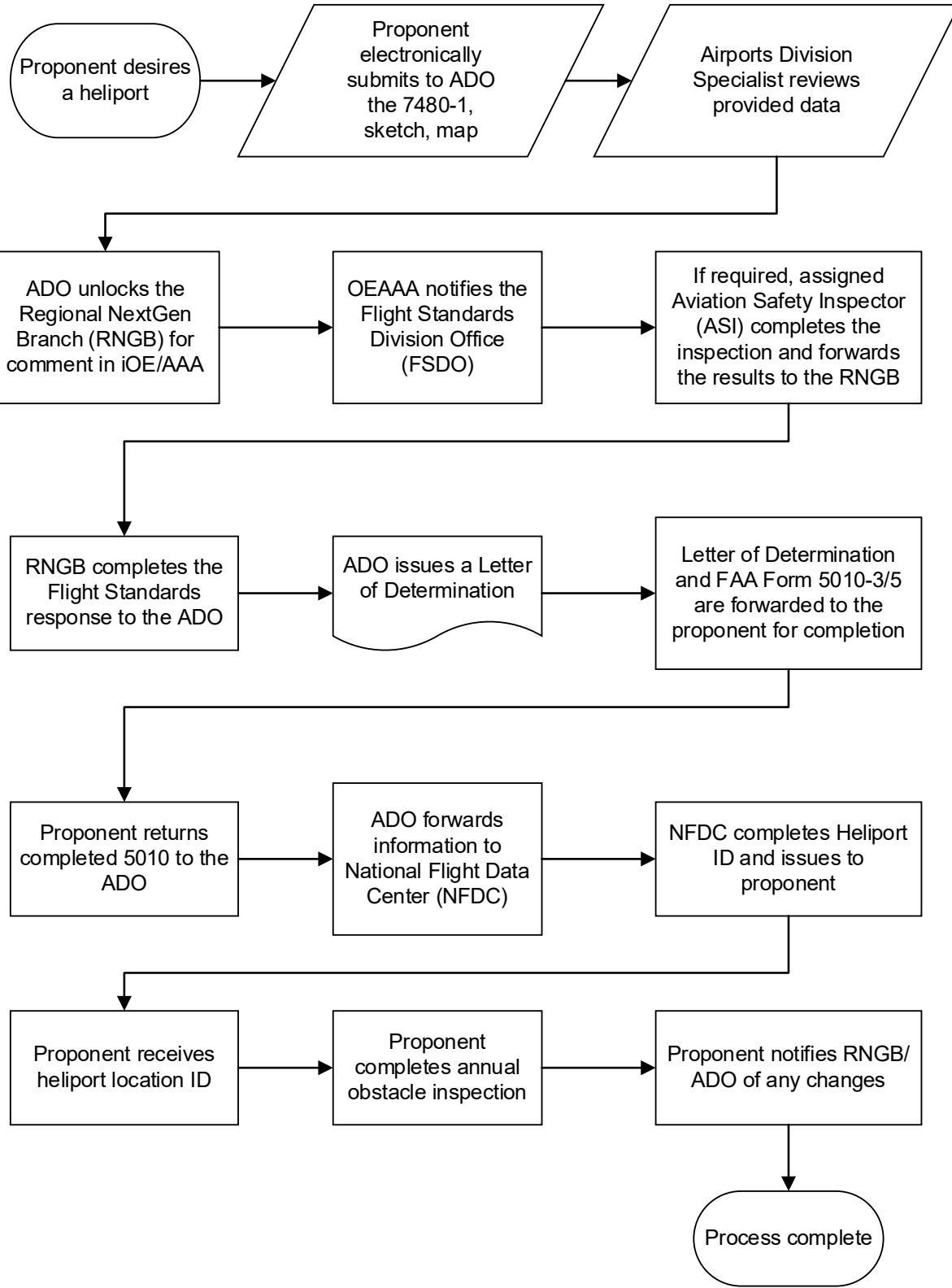
Page Intentionally Blank
APPENDIX G. DESIGN REQUIREMENTS FOR HELIPORT PERIMETER LIGHTING
G.1 Elevated and In-pavement Omnidirectional Helipad Perimeter Light.
G.1.1 Horizontal Beam Coverage.
Approaches to heliports are typically performed into the prevailing wind direction. Helicopters can approach the heliport from any direction. Ensure the intensity for heliport perimeter lighting is maintained for all possible directions of approach, requiring an omnidirectional horizontal light geometry.
G.1.2 Vertical Beam Coverage.
The approach paths flown by the helicopter pilot dictate the required vertical intensity coverage of the light fixture. The FAA Flight Standards Service determined the vertical approach paths used by most helicopters making approaches to a heliport in VMC due to limited availability of accurate data. See Table G-1.
Table G-1. Helicopter Approach Angles Assuming VMC
| Approach | Typical Descent Angle |
| Shallow | 3 degrees to 5 degrees |
| Normal | 7 degrees to 12 degrees |
| Steep | 12 degrees to 15 degrees |
The approach path data were converted to the corresponding angle of elevation from the heliport perimeter lighting as a function of range. The mean angle of elevation and the upper and lower limits of the vertical beam spread will increase as the range from the heliport decreases. By controlling the vertical intensity distribution of the heliport perimeter lighting as a function of elevation, it is ensured that the lighting is sufficiently bright to be seen at the required range without glare at closer ranges.
G.1.3 Helipad Perimeter Lighting Intensity.
The intensity requirements were developed into a specification that can be used by industry to produce and install optimized perimeter lighting. The intensity specification is based on a currently available light fixture FAA type L-860E that was determined to be the most effective in meeting the need for the pilot to be able to clearly see the perimeter lighting.
G.1.4 Helipad Perimeter Lighting Chromaticity.
Ensure helipad perimeter light fixtures meet chromaticity requirements for aviation green per AC 150/5345-46 and SAE AS 25050, Colors, Aeronautical Lights and Lighting Equipment, General Requirements For, when using incandescent lights. For light fixtures that use light emitting diodes (LEDs) see the requirements in Engineering Brief #67.
G.2 Photometric Requirements.
Refer to Table G-2 for the heliport perimeter light fixture photometric requirements.
Figure G-1 illustrates the proposed light fixture intensity distribution.
Table G-2. Perimeter Lighting Intensity Recommendations
| 0 to 15 degrees | 16 to 90 degrees | ||
| Color | Minimum | Minimum averageintensity | Minimum |
| Green | 10 | 15 | 5 |
See AC 150/5345-46D, Specification/or Runway and Taxiway Light Fixtures, paragraph
3.3, Photometric Requirements, for detailed measurement methods and requirements.
Figure G-1. Perimeter Light Intensity Distribution
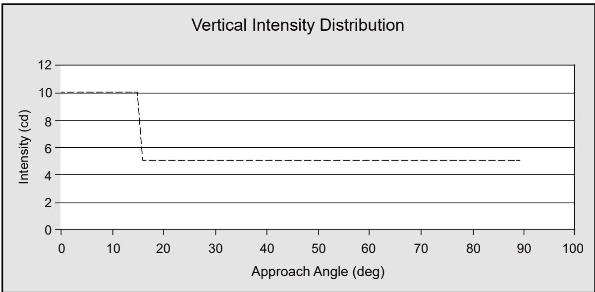
G.3 Additional Heliport Perimeter Light Requirements.
The construction, materials, environmental requirements, and production testing for the qualification and acceptance of elevated helicopter perimeter light fixtures, per AC 150/5345-46.
G.3.1 LED Light Fixtures.
The additional requirements in Engineering Brief #67 are applicable for light fixtures that use LEDs.
Some night vision goggle systems may not detect specific LED colors.
G.3.2 Light Fixture Type Number.
The light fixtures will be listed in AC 150/5345-46 as FAA type L-860H, elevated heliport perimeter light and Type L-852H, in-pavement heliport perimeter light.
G.3.3 Light Base Requirements.
Elevated heliport perimeter light fixtures will be installed in a load-bearing light base (L-868, Size B) or non-load-bearing light base (L-867, Size B), per AC 150/5345-42. Shallow base type light bases will not be used.
G.4 L-860H and L-852H Light Fixture Testing.
G.4.1 Laboratory Testing.
The prototype L-860H and L-852H light fixture will be fully characterized in the laboratory using a goniometer and calibrated photo-detector for spatial light intensity distribution. For vertical angles of 0 to 10 degrees, the light intensity will be measured for each 1 degree vertically over 360 degrees horizontally (5-degree intervals). For vertical angles of 10 to 90 degrees, visually verify the projected light intensity.
All testing requirements specified in AC 150/5345-46 will be observed except for photometric requirements.
G.4.2 Reports.
At the conclusion of all testing, the manufacturer will generate a report that details the photometric testing results in the laboratory per paragraph G.4.1.
G.4.3 Production.
All subsequent L-860H and L-852H light fixture production will be based upon the documented results of testing, per paragraph G.4.1.
G.5 Installation Criteria.
Heliport light fixtures will be installed in accordance with the requirements of AC 150/5340-30.
Advisory Circular Feedback
If you find an error in this AC, have recommendations for improving it, or have suggestions for new items/subjects to be added, you may let us know by (1) mailing this form to Manager, Airport Engineering Division, Federal Aviation Administration ATTN: AAS-100, 800 Independence Avenue SW, Washington DC 20591 or (2) faxing it to the attention of the Office of Airport Safety and Standards at (202) 267-5383.
Subject: AC 150/5390-2D
Date:
Please check all appropriate line items:
☐ An error (procedural or typographical) has been noted in paragraph on page .
☐ Recommend paragraph on page be changed as follows:
☐ In a future change to this AC, please cover the following subject: (Briefly describe what you want added.)
☐ Other comments:
☐ I would like to discuss the above. Please contact me at (phone number, email address).
Submitted by:
Date: