MinerU OCR: CASA Vertiport Design Draft
ADVISORY CIRCULAR AC 139.V-01v1.0
Guidelines for vertiport design
Date
File ref
November 2022
D22/317489
Advisory circulars are intended to provide advice and guidance to illustrate a means, but not necessarily the only means, of complying with the Regulations, or to explain certain regulatory requirements by providing informative, interpretative and explanatory material.
Advisory circulars should always be read in conjunction with the relevant regulations.
Audience
This advisory circular (AC) applies to:
persons involved in the design, construction, and operation of vertiports
proponents of vertiports
advanced air mobility (AAM) aircraft owners/operators
aerodrome operators
the Civil Aviation Safety Authority (CASA).
Purpose
This AC provides initial guidance in the planning and design for vertiports to support the safe and efficient operation of vertical take-off and landing capable aircraft VTOL-capable aircraft operating with a pilot on board in visual conditions only.
This AC is not intended to restrict or limit a pilot or operator from determining the most suitable area for landing or take-off for the VTOL-capable aircraft operation.
These specifications for vertiport planning and design have been prepared to support the progress of necessary aerodrome infrastructure. The guidance outlined in this AC is adaptable and structured to evolve with this emerging sector.
This AC is the first in a collection of guidance material to be published. Additional ACs and supplementary material will provide further detail on design concepts as well as address operational considerations such as inspections, aeronautical data and obstacle control.
For further information
For further information, contact CASA’s Personnel Licensing, Aerodromes and Air Navigation Standards (PLAANS) (telephone 131 757).
Unless specified otherwise, all subregulations, regulations, Divisions, Subparts and Parts referenced in this AC are references to the Civil Aviation Safety Regulations 1998 (CASR).
Status
This version of the AC is approved by the Branch Manager, Flight Standards.
| Version | Date Details | |
| v1.0 | November2022 | Initial Draft AC. |
Contents
1 Reference material 4
1.1 Acronyms 4
1.2 Definitions 4
2 Introduction 8
2.1 Background 8
2.2 Site selection 8
3 Vertiport physical characteristics 11
3.1 General 11
3.2 Essential vertiport components 12
3.3 Optional vertiport components 14
4 Obstacle limitation surfaces 19
4.1 Obstacle limitation surfaces origins 19
4.2 Surfaces 21
5 Visual aids 25
5.2 Markers and markings - general 25
5.3 Markers and markings - final approach and take-off areas 25
5.4 Markers and markings - taxiways and stands 31
5.5 Visual Aids - Lighting 34
5.6 Machine-readable visual aids 39
1 Reference material
1.1 Acronyms
The acronyms and abbreviations used in this AC are listed in the table below.
| Acronym | Description |
| AAM | Advanced Air Mobility |
| AC | advisory circular |
| AFM | aircraft flight manual |
| CASA | Civil Aviation Safety Authority |
| CASR | Civil Aviation Safety Regulations 1998 |
| FATO | final approach and take-off area |
| FPA | FATO protection area |
| FPAGLS | flight path alignment guidance lighting system(s) |
| ICAO | International Civil Aviation Organization |
| MTOW | maximum take-off weight |
| OFV | obstacle free volume |
| OLS | obstacle limitation surface |
| RTODRV | rejected take-off distance required (for VTOL-capable aircraft) |
| SARPS | standards and recommended practices of ICAO |
| STOL | short take-off and landing |
| TDPC | touchdown/positioning circle |
| TDPM | touchdown/positioning marking |
| TLOF | touchdown and lift off area |
| UCW | undercarriage width |
| VCA | VTOL-capable aircraft |
| VPS | vertical procedure surface |
| VTOL | vertical take-off and landing |
1.2 Definitions
Terms that have specific meaning within this AC are defined in the table below. Where definitions from the civil aviation legislation have been reproduced for ease of reference, these are identified by 'grey shading'. Should there be a discrepancy between a definition given in this AC and the civil aviation legislation, the definition in the legislation prevails.
| Term | Definition |
| aerodrome | An area on land or water (including any buildings, installations, and equipment), the use of which as an aerodrome is authorised under the regulations, being such an area intended to be used either wholly or in part for the arrival, departure, and movement of aircraft. |
| barrette | means 3 or more lights closely spaced in a transverse line so that from a distance they appear as a short bar of light. |
| D | for VCA, means the diameter of the smallest circle enclosing the aircraft projected on a horizontal plane, while the aircraft is in the take-of or landing configuration, with ift/thrust units turning, if applicable. |
| Note: If the aircraft changes dimensions during taxing or parking (e.g., folding wings), a corresponding Dtaxing or Dparking should also be provided. | |
| Design D design aircraft | The D of the design aircraft. means a virtual aircraft type that has the largest set of dimensions, the |
| greatest maximum take-off weight (MTOW), and the most critical obstacle avoidance criteria of the aircraft that the vertiport, or for a defined area within the vertiport, is intended to serve. | |
| D-Value | A limiting dimension, in terms of D, for a vertiport, or for a defined area within the vertiport. is a vertiport with a FATO location that would introduce a risk of fall from |
| height or introduces a hazard to aircraft operations or to other people within the structure under the vertiport. | |
| elongated | when used with TLOF or FATO, elongated means an area which has a length more than twice its width. |
| final approach and take- | For the operation of a VCA, is defined as a solid area: |
| off area (FATO) | a. from which a take-off is commenced; or b. over which the final phase of approach to hover is completed. |
| lighting element | A lighting element is a light source within a lighting segment that may be discrete (e.g., a Light Emitting Diode (LED)) or continuous (e.g., fibre optic cable, electro luminescent panel). An individual lighting element may consist of a single light source or multiple light sources arranged in a group or cluster and may include a lens/diffuser. |
| lighting segments | Lighting segments are low profile lighting fixtures that consists of a line of lighting elements within unit or frame. For the purposes of this circular, the dimensions of a lighting segment are the length and width of the smallest possible rectangular area that is defined |
| obstacle | Arrays of segmented point source lighting (ASPSL) or luminescent panels (LPs) are examples of lighting segments. An object (whether temporary or permanent) or part of such an object that: |
| obstacle free volume | a. is located on an area provided for the movement of aircraft; or b. extends above a defined surface designated to protect aircraft in flight is a defined volume of airspace between the FATO protection area and the |
| protection area | means a defined area on a vertiport, which surrounds either the FATO or a stand, intended to reduce the risk of damage to an aircraft diverging from the FATO or stand. |
| reference circle | is a horizontal circle, of the specified dimension, that is centred on any intended position/flight path at or above the applicable area/surface. |
| rejected take-off distance required (RTODRV) | means the horizontal distance that is required from the start of the take-off to the point where the aircraft comes to a full stop, following a critical failure that is recognised at the TDP. |
| take-off decision point (TDP) | means the first point that is defined by a combination of speed and height from which a safe take-off can be continued following a critical failure and is the last point in the take-of path from which a rejected take-off is ensured. |
| touchdown and lift-off area (TLOF) | an area where a VTOL-capable aircraft may touch down or lift off. |
| touchdown/positioning circle (TDPC) | a TDPM in the form of a circle, which is used for omnidirectional positioning in a TLOF. |
| touchdown/positioning marking (TDPM) | a marking or set of markings that provide visual cues for the directional positioning of an aircraft. |
| vertical procedures | take-off and landing procedures that include an initial and/or final vertical profile. The profile may or may not include a horizontal component. |
| vertical procedure | a surface at which a VTOL-capable aircraft either: |
| surface (VPS) | a. begins its arriving vertical procedure, or b. ends its departing vertical procedure. |
| vertiport elevation | the highest point of the FATO, or where there are multiple FATOs, the highest point of the highest FATO. |
| vertiport | an area of land, water, or structure that is used or intended to be used for the landing, take-off, and movement of VTOL-capable aircraft, that meets or exceeds the specifications contained within this advisory circular. |
| For the purposes of this AC the term vertiport also includes vertihubs and vertistops: | |
| • Vertihub: a vertiport with infrastructure for maintenance, repair, fuelling, and parking spaces for storage of VCA. | |
| • Vertistop: a vertiport intended for take-of and landing of VCA to drop off or pick up passengers or cargo, but where there are no facilities for fuelling, defueling, scheduled maintenance, scheduled repairs, or | |
| vertiport clearway | storage of aircraft. means a defined horizontal surface selected and/or prepared as a suitable area over which an aircraft, capable of continued safe flight after a critical |
| failure, may operate between the FATO/VPS and the approach/climb-out surface inner edge. | |
| VTOL-capable aircraft (VCA) | a heavier-than-air aircraft, other than aeroplane or helicopter, capable of performing vertical procedures by means of more than two lift/thrust units. |
| VCA stand | a defined area that is intended to accommodate aircraft for loading or unloading passengers, mail, or cargo, fuelling/charging, parking, or |
| VCA taxi-route | a defined path that is established for the movement of VCA from one part of a vertiport to another: |
| a. an air taxi-route: a marked taxi-route that is intended for air taxing; and | |
| b. a ground taxi-route: a marked taxi-route centred of a taxiway that is intended for ground movement. | |
| VCA taxiway | a defined path on a vertiport that is intended for the ground movement of VCA from one part of a vertiport to another. |
2 Introduction
2.1 Background
2.1.1 AAM is an evolving aviation ecosystem that involves a range of innovative aircraft types (both crewed and uncrewed) which will transport passengers and larger freight. Innovative aircraft types may span from multi-rotor, tilt wing, tilt-rotor, powered wing, offering short take-off and landing (STOL) through to vertical take-off and landing (VTOL) capabilities.
2.1.2 This AC provides guidance on the design elements and specifications of vertiports. This document assumes initial operations of vertical take-off and landing (VTOL)-capable aircraft (VCA) operated by pilot-on-board flying visual operations only.
2.1.3 With (AAM) evolving rapidly, these specifications for vertiport planning and design have been prepared to support the progress of necessary aerodrome infrastructure. The guidance outlined in this AC is adaptable and structured to evolve with this emerging sector.
2.1.4 However, it should be noted that these specifications are subject to change as aircraft performance and other data becomes available. Likewise, International Civil Aviation Organization (ICAO) Standards and Recommended Practices (SARPS) and other international standards are also in development and subsequently may impact this guidance. Any significant revision of this guidance will be subject to industry consultation.
2.1.5 In addition to this, the introduction of AAM may impact and be impacted by considerations other than of aviation safety, such as security, noise and environment. Vertiport owners and operators should refer to local, state and other federal agencies to ensure appropriate adherence to all relevant requirements.
2.1.6 This AC provides specifications for vertiport facilities associated with the intended operation of VCA without mandating a standard vertiport layout
2.2 Site selection
2.2.1 Fundamental considerations
2.2.1.1 The selection of a vertiport site involves the consideration of a range of variables including intended aircraft types, area available, vertiport configuration and the current or future obstacle environment.
2.2.1.2 Full consideration of some of the variables relies on effective engagement with a range of stakeholders. Vertiport operators should establish open communication channels with aircraft operators, government stakeholders, nearby aerodrome operators (including certified aerodromes, non-certified aerodromes, helicopter landing sites and other vertiports) and, where appropriate, the local community.
2.2.1.3 The aircraft type or types that are expected to use the vertiport form the basis for most design considerations when developing a vertiport. Where the vertiport operator intends on supporting a single aircraft type, that aircraft type will be the design aircraft. For vertiports intended to service multiple aircraft, the design aircraft is a virtual aircraft composed of the most demanding characteristics of these aircraft including the largest set of dimensions, the greatest maximum take-off weight (MTOW), and the most critical flight path requirements (i.e., approach/climb-out gradient and/or horizontal flight requirements following a critical failure).
2.2.1.4 The vertiport area available and the intended scope of operations may impact on the vertiport configuration. The number of facilities, such as final approach and take-off areas (FATO), taxi routes, stands and associated buildings may be limited by the physical environment.
2.2.1.5 The potential for a vertiport to be constructed in a complex wind (turbulent) environment means that specific considerations should be made when a vertiport is to be established in the vicinity of buildings and significant terrain.
2.2.1.6 For vertiports within obstacle-rich environments or that may be impacted by future development, careful consideration of preferred and/or future flight paths should be made in consultation with appropriate stakeholders.
2.2.1.7 This AC does not cover all vertiport development considerations. Vertiport owners and operators may need to consult appropriate stakeholders on topics including but not limited to noise, security, environmental concerns and privacy.
2.2.2 Proximity to other vertiports or other aerodrome infrastructure
2.2.2.1 Where vertiports are located within the vicinity of other vertiports or aerodromes, the siting and design of FATOs and their associated flight paths should be carefully considered to minimize the interactions between vertiport traffic and other vertiport and aerodrome traffic.
2.2.3 Downwash protection
2.2.3.1 A vertiport should be located and designed in a way to protect the following from damage or injurious effects of downwash associated with VCA operating to/from the vertiport:
people
other aircraft
buildings
vehicles
equipment.
2.2.3.2 An initial evaluation of downwash impacts may be carried out using the values of Table 1. However, the evaluation should be complemented by a study taking into account the specific local conditions and relevant wind comfort criteria of the affected persons and facilities.
2.2.3.3 A detailed safety assessment and an operational evaluation of individual aircraft types operating to/from a given vertiport may be undertaken.
Table 1: Guidelines for maximum downwash velocity
| Type of area | Maximumvelocity |
| Areas of a vertiport traversed by flight crew, or passengers, boarding or leaving an aircraft|6o km/h | |
| Any personnel working near an aircraft | 80km/h |
| Equipment on an apron | 80 km/h |
| Public roads where the vehicle speed is likely to be 80 km/h or more | 50 km/h |
| Public roads where the vehicle speed is likely to be less than 80 km/h | 60km/h |
| Public areas, within or outside the vertiport boundary, where passengers or members ofthe public are likely to walk or congregate | 60km/h |
| Public areas where passengers or others are not likely to congregate | 80 km/h |
| Buildings and other structures | 100 km/h |
3 Vertiport physical characteristics
3.1 General
3.1.1.1 A vertiport consists of set of essential components, or defined areas, as well as some optional components. These are building blocks of a vertiport, as shown in Figure 1, and include:
a. one or more FATO
b. one or more touch down and lift-off areas (TLOF)
c. protection areas
d. taxiways and/or taxi-routes
e. stands.
3.1.1.2 The following specifications are based on the design assumption that no more than one VCA will be in the FATO at the same time.
3.1.1.3 Further, it is also assumed that operations to/from a FATO in proximity to another FATO will not be simultaneous. If simultaneous operations are planned, appropriate separation distances between FATOs should be determined with due regard to issues such as downwash, flight paths and other airspace limitations.
3.1.1.4 Safety devices to mitigate the risk of fall from height at elevated vertiports should not penetrate the OLS or exceed the height of the protection area.

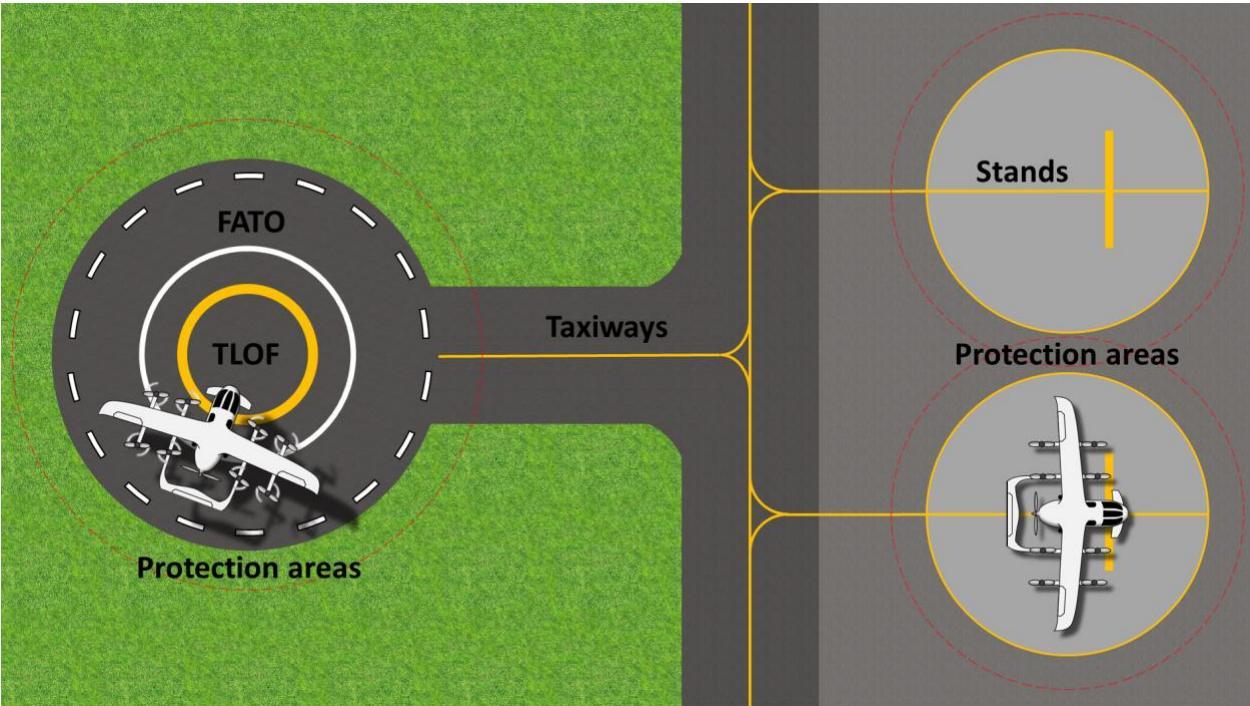
Figure 1: Vertiport components
3.2 Essential vertiport components
3.2.1 Final approach and take-off area
3.2.1.1 A vertiport should be provided with at least one FATO.
3.2.1.2 A FATO should have the following features:
a. A sufficient size and shape to ensure containment of every part of the design aircraft in the final phase of approach and commencement of take-off in accordance with the intended procedures. The shape of the FATO is optional as represented in Figures 1, 2 and 12.
b. When collocated with a TLOF area, contiguous and flush with the TLOF, and meeting the requirements of 3.2.2.3 b.
c. When non-collocated with a TLOF, free of obstacles, except for essential objects, free of hazards to a potential forced landing and resistant to the effects of downwash.
3.2.1.3 The dimensions of a FATO should be the:
a. length of the rejected take-off distance required (RTODRV) prescribed in the design aircraft flight manual (AFM), or 1.5 Design D, whichever is greater
b. width prescribed in the design aircraft AFM, or 1.5 Design D, whichever is greater.
3.2.1.4 Essential objects should not exceed 5 cm in height.
3.2.1.5 The slope of a FATO should not exceed 2 % in any direction.
3.2.1.6 A FATO should be located to minimize the influence of the surrounding environment, including turbulence, which could have an adverse impact on aircraft operations.
3.2.1.7 A FATO should be surrounded by a FATO Protection Area (FPA), refer to Section 4.1.1 of this AC.
3.2.1.8 The distance between any two proximate FATOs should be determined by a safety assessment.
3.2.2 Touchdown and lift-off area
3.2.2.1 A vertiport should be provided with at least one TLOF.
3.2.2.2 A TLOF should be provided within a FATO as shown in Figure 2, or stand as shown in Figure 12c, whenever it is intended that the undercarriage of the VCA will touch down or lift off.
3.2.2.3 A TLOF should have the following features:
a. A sufficient size and shape to ensure containment of the undercarriage of the design aircraft aligned with the intended orientation.
b. An area which:
i. is free of obstacles
ii. has sufficient bearing strength to accommodate the dynamic loads associated with the design aircraft.
iii. is free of irregularities that would adversely affect the touchdown, lift-off or taxi of VCA
iv. has sufficient friction to avoid skidding of VCA or slipping of persons
v. is resistant to the effects of downwash
vi. ensures effective drainage while having no adverse effect on the control or stability of a VCA during touchdown, lift-off, or when stationary.
3.2.2.4 The minimum dimensions of a TLOF should be the dimensions prescribed in the design aircraft AFM, or 0.83 Design D, whichever is greater.
3.2.2.5 The slope of a TLOF should not exceed 2 % in any direction.
3.2.2.6 When a TLOF is within a FATO, it should be:
a. centred on the FATO
or
b. for an elongated FATO, centred on the longitudinal axis of the FATO.
3.2.2.7 When a TLOF is within a VCA stand, it should be centred on the stand.

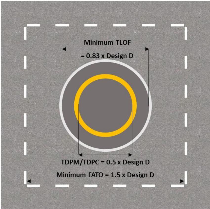
Figure 2: FATO, TLOF (with TDPC)
3.3 Optional vertiport components
3.3.1 VCA taxiways
3.3.1.1 A VCA taxiway should be provided for the intended ground movement of a VCA within the vertiport under its own power or by means of ground movement equipment.
3.3.1.2 A VCA taxiway should be located within a taxi-route and have the following features:
a. sufficient width to ensure containment of the undercarriage of the design aircraft
b. area which:
i. is free of obstacles
ii. has the bearing strength to accommodate the taxiing loads of the aircraft the taxiway is intended to serve
iii. is free of irregularities that would adversely affect the ground taxiing of a VCA
iv. is resistant to the effects of downwash
v. ensures effective drainage while having no adverse effect on the control or stability of a VCA when being manoeuvred under its own power or by ground movement equipment, or when stationary.
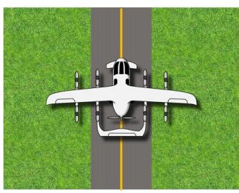
3.3.1.3 The minimum width of a VCA taxiway should be two times the undercarriage width (UCW) of the design aircraft, as shown in Figure 3.
3.3.1.4 The transverse slope of a taxiway should not exceed 2 % and the longitudinal slope should not exceed 3 %.
3.3.1.5 When defining the distance between ground taxiways, the separation distance between an aircraft on a ground taxiway and an aircraft on a parallel ground taxiway or an object should take into consideration a minimum wingtip clearance of at least 0.25 maximum width of the design aircraft.
Note: Where taxiways are intended to be used by vehicles and equipment considerations should be made to taxiway width and bearing strength.

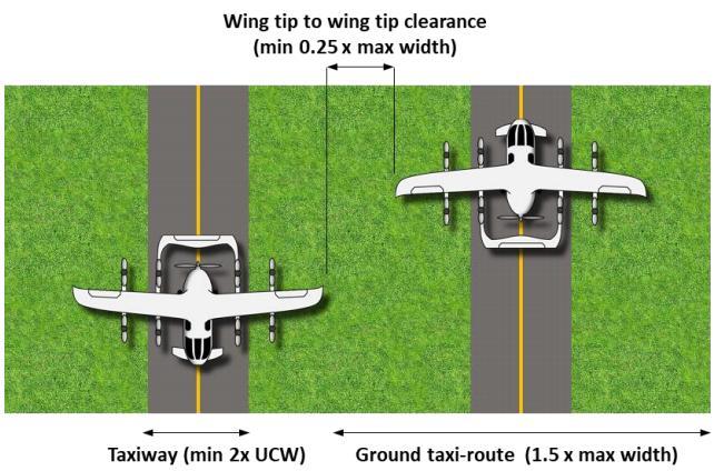

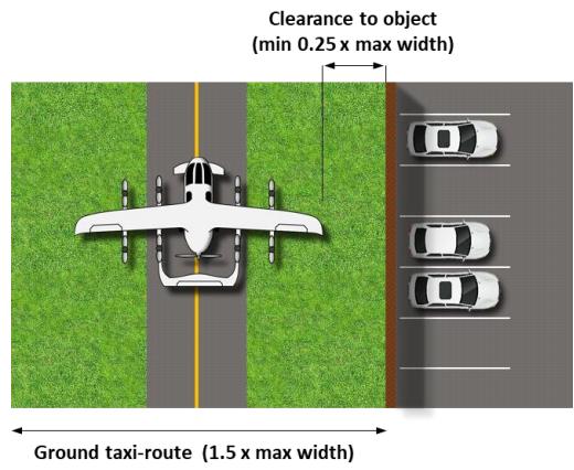
Figure 3: VCA taxiways and clearance distances
3.3.2 Taxi routes for VCA
3.3.2.1 A VCA taxi-route should be provided for the intended movement of a VCA within the vertiport under its own power or by means of ground movement equipment.
3.3.2.2 A VCA taxi-route should have the following features:
a. sufficient width to ensure containment of the design aircraft
b. free of obstacles, except for essential objects
c. resistant to the effects of downwash
d. when collocated with a taxiway:
i. is contiguous and flush with the taxiway
ii. does not present a hazard to operations
iii. ensures effective drainage
iv. not exceed an upward transverse slope of 4 % outwards from the edge of the taxiway.
e. when not collocated with a taxiway, is free of hazards if a forced landing is required.
3.3.2.3 Where collocated with a taxiway, essential objects located in the VCA taxi-route should not:
a. be located at a distance of less than 50 cm outwards from the edge of the taxiway
b. penetrate a surface originating 50 cm outwards of the edge of the taxiway and a height of 25 cm above the taxiway and sloping upwards and outwards at a gradient of 5 % up to the outer edge of the ground taxi-route.
Notes:
-
Where the VCA operating width differs (e.g., folding wings) while taxiing, the reduced width may be considered for defining the taxi-route width.
-
Consideration of low-mounted lift/thrust units may be required to ensure that appropriate clearances are maintained.
Ground taxi-routes for VCA
3.3.2.4 A VCA ground taxi-route should have a minimum width of 1.5 times the overall width of the design aircraft it is intended to serve and be centred on a taxiway, as shown in Figure 4.
Note: Where the VCA operating width differs (e.g., folding wings) while taxiing, the reduced width may be considered for defining the taxi-route width.
Air taxi-route for VCA
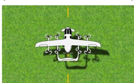
3.3.2.5 A VCA air taxi-route should have a minimum width of twice the overall width of the design aircraft it is intended to serve, as shown in Figure 4.
3.3.2.6 When not collocated with a taxiway, the slopes of the ground below an air taxi-route should not exceed the slope landing limitations of the design aircraft the taxi-route is intended to serve. In any event, the transverse slope should not exceed 10 % and the longitudinal slope should not exceed 7 %.
Ground taxi-route = 1.5 x overall width

Taxiway (min 2x UCW)
Air taxi-route = 2 x overall width

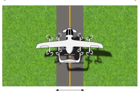
Taxiway (min 2x UCW)
Figure 4: VCA taxi-routes
Air taxi-route = 2 x overall width

3.3.3 VCA stands
3.3.3.1 VCA stands may be provided to permit the safe loading and off-loading of passengers and/or cargo, as well as the servicing of the VCA without interfering with other traffic.
3.3.3.2 A VCA stand should be located within a protection area as shown in Figure 5, and have the following features:
a. sufficient size and shape to ensure containment of every part of the design aircraft when it is being positioned within the stand
b. An area which:
i. is free of obstacles
ii. has bearing strength capable of withstanding the intended loads
iii. is free of irregularities that would adversely affect the manoeuvring of VCA
iv. has sufficient friction to avoid skidding of VCA or slipping of persons
i. is resistant to the effects of downwash
ii. ensures effective drainage while having no adverse effect on the control or stability of a VCA when being manoeuvred under its own power, when being moved by means of ground movement equipment, or when stationary.
3.3.3.3 The slope of a VCA stand in any direction should not exceed 2 %.
D-Value-based VCA stand
3.3.3.4 When the VCA stand design is based on D-value, the minimum dimensions should be:
a. a circle of diameter of 1.2 Design D
or
b. when there is a limitation on manoeuvring and positioning, of sufficient width to meet the requirement of 3.3.3.2 (a) above, but not less than 1.2 times overall width of design aircraft.
Geometry-based VCA stands
Reserved
3.3.4 Protection areas for VCA stands
3.3.4.1 A stand protection area should be provided for VCA stands, as shown in Figure 5.
3.3.4.2 A protection area should have the following features:
a. free of obstacles, except for essential objects
b. resistant to the effects of downwash
c. when solid, flush with the stand, not exceeding an upward slope of 4 % outwards from the edge of the stand and ensures effectively drained.
3.3.4.3 When associated with a stand designed for turning, the protection area should extend outwards from the periphery of the stand for a distance of 0.4 Design D. Otherwise, the minimum width of the stand and the protection area should not be less than the width of the associated taxi-route.
3.3.4.4 When associated with a stand designed for non-simultaneous aircraft operations the:
a. protection area of adjacent stands may overlap but should not be less than the required protection area for the larger of the adjacent standards
b. adjacent stand may contain a static aircraft.
3.3.4.5 Essential objects located in the protection area should not:
a. penetrate a surface at a height of 5 cm above the level of the stand, if located at a distance of less than 0.75 Design D from the centre of the VCA stand
b. penetrate a surface at a height of 25 cm above the level of the stand and sloping upwards and outwards at a gradient of 5 %, if located at a distance of 0.75 Design D or more from the centre of the VCA stand.

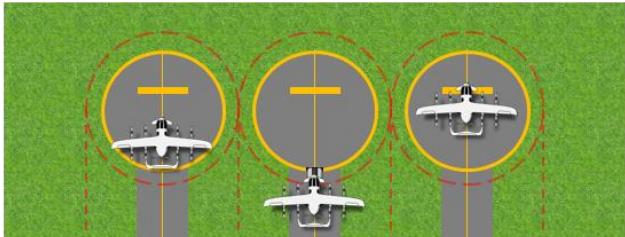
Example A: Ground taxi. Simultaneous taxi-on/push-back stands

Example B: Ground taxi. Simultaneous turning stands

Example C: Ground taxi. Non-simultaneous taxi-on/push-back stands dependent on other stand being clear or with static aircraft


Example E: Air taxi. Simultaneous taxi-through stands
Example D: Ground taxi. Non-simultaneous turning stands dependent on other stand being clear or with static aircraft only

Example F: Air taxi. Simultaneous turning stands

Example G: Air taxi. Non-simultaneous taxi-through stands dependent on other stand being clear or with static aircraft only

Example H: Air taxi. Non-simultaneous turning stands dependent on other stand being clear or with static aircraft only
Figure 5: Protection areas for VCA stands and the associated VCA taxi-routes for different operation scenarios
4 Obstacle limitation surfaces
4.1 Obstacle limitation surfaces origins
The following section outlines the protected areas from which obstacle limitation surfaces (OLS) originate. The dimensions of the OLS rely on a general objective of protection of approach, goaround and balked landing manoeuvres in the visual phase of the approach-to-land below a height of 152 m above the elevation FATO.
4.1.1 Final approach and take-of area protection area
4.1.1.1 An FPA should be provided for each FATO, as shown in Figure 6.
4.1.1.2 An FPA should have the following features:
a. free of obstacles, except for essential objects.
b. where solid, flush with the FATO, resistant to the effects of downwash and ensures effective drainage.
4.1.1.3 Where a FATO supports landing/take-off without vertical procedures, the FPA is an area surrounding the FATO that encompasses:
a. the area(s) bordered by a circumscribed square aligned with the landing/take-off flight path(s) centred on the FPA reference circle(s)
b. any area contained within the direct common tangents of any multiple FPA reference circles.
4.1.1.4 Where a FATO supports landing/take-off with vertical procedures only, the FPA is an area surrounding the FATO that encompasses:
a. the FPA reference circle(s)
b. any area contained within the direct common tangents of any multiple FPA reference circles.
4.1.1.5 The diameter of an FPA reference circle should be the FATO width plus 3 m or 0.25 Design D, whichever is greater.
4.1.1.6 Essential objects located in the FPA should not exceed 25 cm in height and should be frangibly mounted.

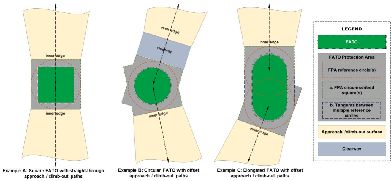
Figure 6 Protection surfaces for vertiports not including vertical procedures
4.1.2 Vertical procedure surface
4.1.2.1 A vertical procedure surface (VPS) should be established for each vertical procedure used for landing or take-off from the vertiport.
4.1.2.2 The VPS is a surface that encompasses the area bordered by a circumscribed square(s) aligned with the intended aircraft flight path(s) centred on the VPS reference circle, as shown in Figure 7.
4.1.2.3 A VPS should be free of obstacles.
4.1.2.4 A VPS reference circle should be established above and centred on the FATO.
4.1.2.5 The diameter of a VPS reference circle should be the diameter of the associated FPA reference circle, plus 1 Design D per 100 ft increase in height above the FATO.
4.1.3 Obstacle free volume
4.1.3.1 An obstacle free volume (OFV) should be established between a VPS and the associated FPA.
4.1.3.2 An OFV should be free of obstacles.
4.1.3.3 The OFV is a truncated cone extending between the edge of the FPA reference circle to the edge of the VPS reference circle, as shown in Figure 7.
4.1.4 Vertiport clearway
4.1.4.1 A vertiport clearway should be established when a VCA needs to manoeuvre, horizontally, between the FPA/VPS outer edge and the approach/climb-out surface inner edge.
4.1.4.2 A vertiport clearway should have the following features:
a. sufficient size and shape to ensure containment of the design aircraft when it is operating between the FPA/VPS and the approach/climb-out surface
b. free of obstacles, except for essential objects
c. resistant to the effects of downwash
d. when at ground level, contiguous surface flush with the FPA, and free of hazards should a forced landing be required.
4.1.4.3 The width of a vertiport clearway should not be less than that of the associated FPA/VPS and centred on the intended flight path, as shown in Figure 6.
4.2 Surfaces
4.2.1 Approach/climb-out surface
4.2.1.1 An approach/climb-out surface should be established for each approach and climb-out flight path to and from the vertiport, as shown in Figures 7, 8 and 9.
4.2.1.2 The approach/climb-out surface consists of an inclined plane or a combination of planes or, when turns are involved, a complex surface, sloping upwards from the inner edge and centred on the intended flight path that must be clear of obstacles.
4.2.1.3 The limits of an approach/climb-out surface should comprise:
a. an inner edge coincident with and of equal length to the outer edge of the associated FPA/VPS/clearway
b. two side edges originating at the ends of the inner edge and diverging uniformly at a specified rate from the vertical plane, aligned with the intended flight path to a specified width and continuing thereafter at that width for the remaining length of the approach/climb-out surface
c. an outer edge horizontal and perpendicular to the centre line of the approach surface intended flight path at a specified height above the vertiport elevation.
4.2.1.4 The specified values of the above characteristics are outlined in Table 2.
Table 2 - OLS surface values - Approach/climb-out surface characteristics
| Characteristic | Value |
| Inner edge width: | Width of FPA/VPS/clearway |
| Day use only final width: | 7x Design D |
| Day use only divergence: | 10% |
| Night use final width: | 10x Design D |
| Night use divergence: | 15% |
| Outer edge height above vertiport elevation | 500(152m) |
4.2.1.5 In the case of an approach/climb-out surface involving turns, the surface is a complex surface containing the horizontal normal to its centre line and the slope of the centre line should be the same as that for a straight approach surface.
4.2.1.6 The slope(s) of the approach/climb-out surface should be measured in the vertical plane containing the centre line of the surface.
4.2.1.7 The approach/climb-out surface slope or combination of slopes and section lengths should be determined with reference to the obstacle environment and intended aircraft performance capabilities. If multiple slope/sections are established, the divergent portion of the approach/climb-out surface should be a single consistent slope.
4.2.2 Transitional surface
4.2.2.1 A transitional surface should be established on each side of an approach/climb-out surface and its associated clearway/VPS/FPA, as shown in Figures 7, 8 and 9.
4.2.2.2 The transitional surfaces should be clear of obstacles.
4.2.2.3 The transitional surface should comprise:
a. a lower edge beginning at the point on the outer edge of the approach/climb-out surface where it reaches its final width then extending downwards and along the side of the approach/climb-out surface to the inner edge and, from there,
b. where a clearway is provided, along the side of the clearway parallel to intended flight path then
c. along the length of the side of the VPS
d. along the length of the side of the FPA parallel to the intended flight path
e. an upper edge beginning at the point where the outer edge of the approach/climbout surface reaches its final width and then parallel to the intended flight path at a constant height.
Note: As the transitional surface is dependent on the approach/climb-out angle and Design D, it may extend the full length of the approach/climb-out surface. It may also be impacted by the extent of any vertical procedure such that it is no longer present.

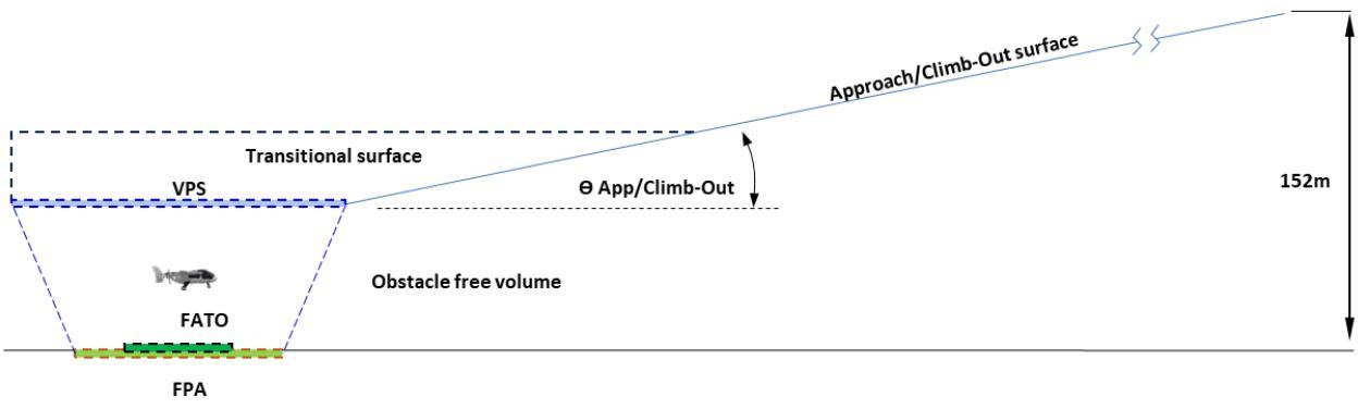

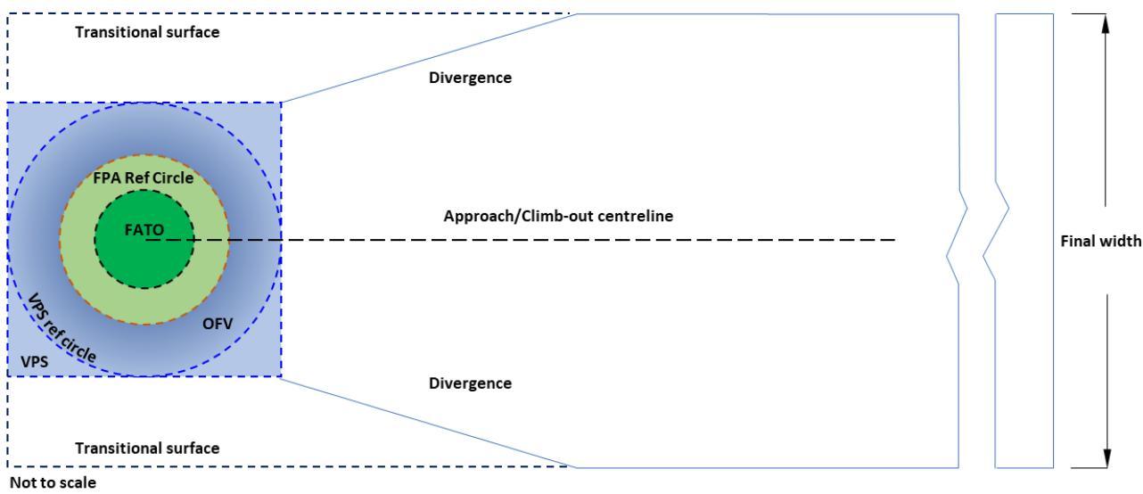
Figure 7: An example OLS design for a vertiport accommodating vertical procedures

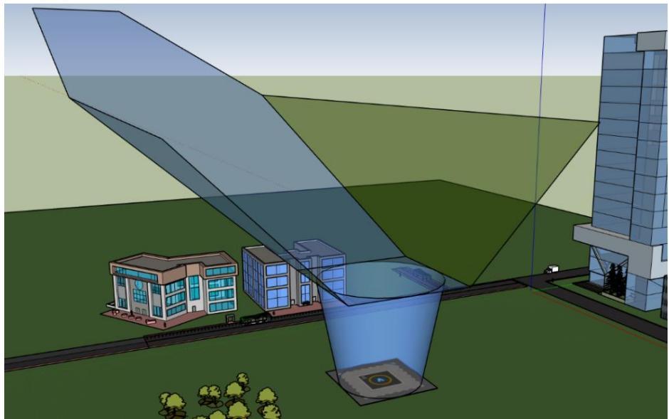
Figure 8: Illustration of a simple vertiport OLS. Showing an OFV, VPS, VPS reference circle, a single approach/climb-out surface and transitional surfaces

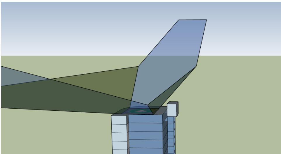
Figure 9: Illustration of a simple elevated vertiport OLS. Showing an FPA, dual approach/climb-out surfaces and transitional surfaces
5 Visual aids
5.1.1 Wind direction indicators
5.1.1.1 A wind direction indicator may be provided at a vertiport to provide a visual indication of the wind direction and speed.
5.1.1.2 A wind direction indicator should be located to indicate the wind conditions over the FATO in such a way as to be free from the effects of airflow disturbances caused by nearby objects or downwash from the lift/thrust units. It should be visible from a VCA in flight, in hover or on the movement area.
5.1.1.3 A wind direction indicator sleeve should be a truncated cone made of lightweight fabric and should have the dimensions of 1.2 m in length, with a diameter of 0.3 m (at the larger end) to 0.15 m (at the smaller end).
5.1.1.4 The colour(s) of the wind direction indicator sleeve should such that it is clearly visible against its visual background.
5.1.1.5 A wind direction indicator at a vertiport intended for use at night should be lit such that it is clearly visible against its visual background.
5.2 Markers and markings - general
5.2.1.1 Markers and markings should be installed, in accordance with the following specifications, at a vertiport available for operations in daylight or at night.
5.2.1.2 Markers and markings should be clearly visible to the VCA and other users by way of:
a. provision of a contrasting background marking (a box or border),
b. where allowed for in the specifications below, the selection of an appropriate contrasting colour
c. any other method that would increase the conspicuity of the marking or marker in operational conditions.
5.2.1.3 The night-time visibility of markers and markings may be supplemented by reflective/refractive material and/or electroluminescent paint providing that such material does not pose a hazard if dislodged.
5.3 Markers and markings - final approach and take-off areas
5.3.1 Flight path alignment guidance marking
5.3.1.1 Flight path alignment guidance marking(s) should be provided at a vertiport where it is desirable and practicable to indicate available approach and/or departure path direction(s).
5.3.1.2 The flight path alignment guidance marking should be located in a straight line along the direction of landing and/or take-off path to the FATO.
5.3.1.3 A flight path alignment guidance marking should consist of each of the following characteristics:
a. one or more arrows marked on the TLOF, FATO and/or FPA.
b. the stroke of the arrow(s) should be 0.5 m in width and at least 3 m in length.
a. take the form shown in Figure 10 which includes the scheme for marking ‘heads of the arrows’ which are constant regardless of stroke length.
5.3.1.4 In the case of a flight path limited to a single landing direction or single take-off direction, the arrow marking may be unidirectional. In the case of a vertiport with only a single landing/take-off path available, one bidirectional arrow is marked, as shown in Figure 15a.
5.3.1.5 The marking should be white.

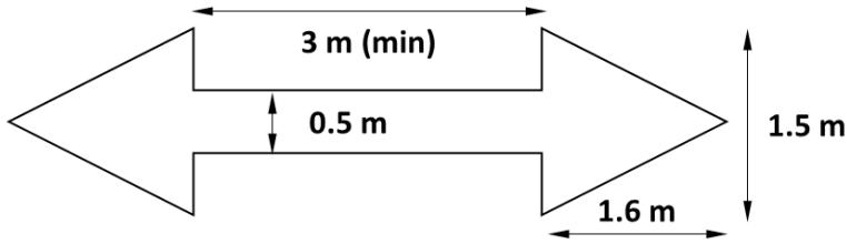
Figure 10: Flight path alignment guidance marking
5.3.2 FATO perimeter marking or markers
5.3.2.1 FATO perimeter markings or markers should be provided at a vertiport where the extent of a FATO is not self-evident, as shown in Figures 12a, 12b, 12c and 12d.
5.3.2.2 For an unpaved FATO, the perimeter should be defined by flush in-ground markers.
5.3.2.3 For a paved $\mathsf { F A T O } ,$ the perimeter should be defined with a painted dashed line.
5.3.2.4 The FATO perimeter marking, or markers should have the following characteristics:
a. be located on the edge of the FATO
b. be 30 cm in width, and 1.5 m in length
c. have end-to-end spacing of not less than 1.5 m and not more than 2 m with corners of a square or rectangular FATO defined
d. be coloured white.
5.3.3 TLOF perimeter marking
5.3.3.1 A TLOF perimeter marking should be displayed if the perimeter of the TLOF is not selfevident, as shown in Figures 12a, 12b, 12c and 12d.
5.3.3.2 A TLOF perimeter marking should be located along the edge of the TLOF.
5.3.3.3 A TLOF perimeter marking should consist of a continuous white line with a width of 30 cm.
5.3.4 Touchdown positioning marking
5.3.4.1 A touchdown/positioning marking (TDPM) should be provided where a VCA is to touchdown or be accurately placed in a specific position, as shown in Figures 12a, 12b, 12c and 12d.
5.3.4.2 The TDPM should be:
a. when there is no limitation on the direction of touchdown/positioning, a touchdown/positioning circle (TDPC) marking
a. when there is a limitation on the direction of touchdown/positioning a single shoulder line with an associated centreline
5.3.4.3 The TDPM should have the following characteristics:
a. the inner edge/inner circumference of the TDPM should be at 0.25 Design D from the centre of the area in which the VCA is to be positioned.
a. when a shoulder line, the length of the marking should be 0.5 Design D
b. be a yellow line with a width of at least 0.5 m.
5.3.4.4 The TDPM should be the primary marking when used in conjunction with other markings on the TLOF.
5.3.5 Aiming point marking
5.3.5.1 An aiming point marking should be provided at a vertiport where it is necessary for a pilot to make an approach to a particular point above a FATO before proceeding to a TLOF, as shown in Figure 12c. The aiming point marking should be located at the centre of the FATO
5.3.5.2 The aiming point marking should have the following characteristics:
a. be an equilateral triangle with the bisector of one of the angles aligned with the preferred landing direction
a. consist of continuous lines
b. the dimensions of the marking should conform to those shown in Figure 11.

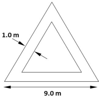
Figure 11: Aiming point marking
5.3.6 Vertiport identification marking
5.3.6.1 A vertiport identification marking may be provided within a FATO, as shown in Figures 12a, 12b and 12d.
5.3.6.2 Where a TDPC is provided, the vertiport identification marking should be in the centre of the TDPC. Otherwise, the vertiport identification marking should be located at or near the centre of the FATO.
5.3.6.3 A vertiport identification marking should have the following characteristics:
a. a form that identifies the vertiport
b. have colour(s) that do not conflict with or detract from the TDPC, where used
c. have a size that not less than 3 m and not greater than 0.5 Design D in its longest dimension
d. have a form that allows the marking to be aligned with the preferred landing direction.
5.3.6.4 The use of the letter "H" and "X" should not be used to avoid confusion with the heliport identification and unserviceability markings, respectively.
Note: The vertiport identification marking need not be limited to a single form for all vertiports. However, the marking used should be consistent across a facility. For example, a vertiport operator may choose to use a vertiport identification marking defined by another aviation authority, or they may choose to use a corporate logo or brand that aligns with the characteristics in 5.3.6.3.
5.3.6.5 Where a vertiport is equipped with two or more FATOs, vertiport identification markings may be supplemented or replaced with an ordinal number marking, as shown in Figure 12d.
5.3.6.6 An ordinal number FATO marking should consist of the following characteristics:
a. arranged as to be readable from the preferred landing direction
b. a number, beginning with 1 and ending in the last of the numbered FATOs
c. have a colour consistent with the vertiport identification marking
d. have a size not less than 1.5 m and not greater than 0.5 Design D in its longest dimension.
5.3.7 Vertiport name marking
5.3.7.1 A vertiport name marking may be provided at a vertiport, as shown in Figure 12d.
5.3.7.2 A vertiport name marking should consist of the name or the alphanumeric designator of the vertiport.
5.3.7.3 A vertiport name marking intended for use at night should be illuminated, either internally or externally.
5.3.7.4 The characters of the marking should be not greater than 1.2 m in height.

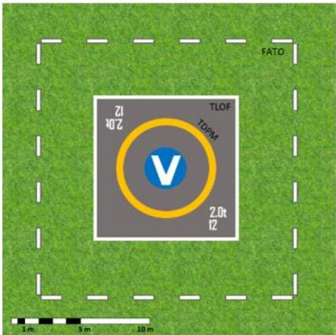
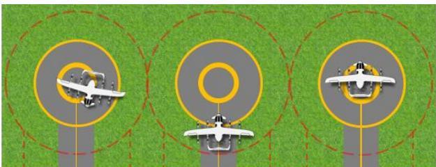
Figure 12a: Vertiport marking example 1
Figure 12a illustrates an example of marking a FATO on a natural surface and includes:
- FATO – Natural surface. White flush markers (1.5m x 0.3m)
- TLOF – Grey painted square with edge marked by continuous white line (>0.3m)
- TDPM – Always an internal diameter 0.5 of Design D. Marked by a continuous yellow circle (0.5- 1m wide)
- vertiport identification – European Union Aviation Safety Agency (EASA) white V on a blue background
- D-Value and maximum allowable weight markings.
Note: The image is an example only and does not limit possible marking combination on a natural surface.

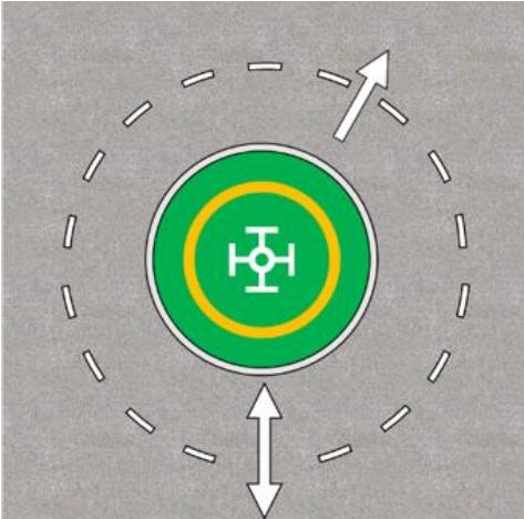
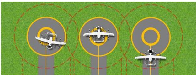
Figure 12b: Vertiport marking example 2
Figure 12b illustrates an example of marking a FATO on a paved surface and includes:
- FATO – Light coloured paving. White markings (1.5m x 0.3m) with black outline for contrast with paving
- TLOF – Green painted circle with edge marked by continuous white line (>0.3m) and a black outline for contrast with paving
- TDPM – Always an internal diameter 0.5 of Design D. Marked by a continuous yellow circle (0.5- 1m wide)
- vertiport Identification – Federal Aviation Administration broken wheel
- 2 types of flight path alignment guidance markings.
Note: The image is an example only and does not limit possible marking combination on a paved surface.

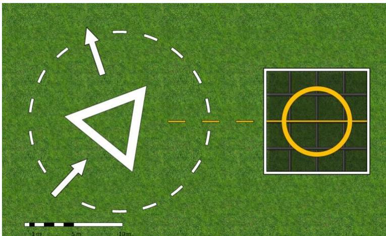
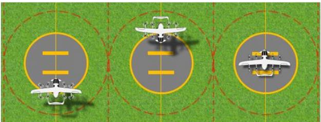
Figure 12c: Vertiport marking example 3
Figure 12c illustrates an example of marking a FATO with an aiming point and stand and includes:
- FATO – Natural surface. White flush markers (1.5m x 0.3m)
- Air-taxi route markers – 1.5 m x 0.15 m yellow markers
- TLOF – Mesh deck with edge marked by continuous white line (>0.3m)
- TDPM – Internal diameter 0.5 of Design D, marked by a continuous yellow circle (0.5-1m wide)
- vertiport identification – none
- flight path alignment – white arrow markings.
Note: The image is an example only and does not limit possible marking combinations

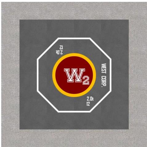
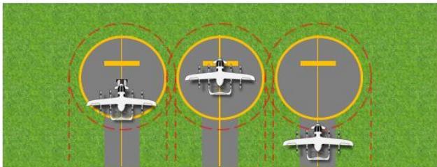
Figure 12d: Vertiport marking example 4
Figure 12d illustrates an example of marking a FATO on a paved surface and includes:
- FATO – Self-evident as dark paving against light concrete
- TLOF (at 1 Design D) – Painted paved octagon with edge marked by continuous white line (>0.3m.)
- TDPM – Internal diameter 0.5 of Design D marked by a continuous yellow circle (0.5-1m wide)
- vertiport identification – Corporate logo with ordinal number
- vertiport name marking.
Note: The image is an example only and does not limit possible marking combinations
5.3.8 Maximum allowable weight marking
5.3.8.1 A maximum allowable weight marking may be displayed to provide the weight limitation of the TLOF, as shown in Figures 12a and 12d.
5.3.8.2 A maximum allowable weight marking should be located within the TLOF.
5.3.8.3 A maximum allowable weight marking should consist of a one-, two- or three-digit number.
5.3.8.4 The maximum allowable weight should be expressed in tonnes to the nearest 100 kg. The marking should be presented to one decimal place and rounded to the nearest 100 kg followed by the lower case letter “t”.
5.3.8.5 The maximum allowable weight marking should consist of the following characteristics:
a. arranged as to be readable from the preferred landing direction.
b. have a size that not less than 0.6 m in its longest dimension.
5.3.9 D-Value marking
5.3.9.1 A D-value marking may be displayed to provide the pilot with the limiting D of the FATO or TLOF, as shown in Figures 12a and 12d.
5.3.9.2 A D-value marking should be located within the FATO or TLOF and so arranged as to be readable from the preferred landing direction(s).
5.3.9.3 The D-value marking should be rounded to the nearest whole metre with 0.5 rounded down.
5.3.9.4 The D-Value marking should consist of the following characteristics:
a. arranged as to be readable from the preferred landing direction
b. have a size that not less than 0.6 m in its longest dimension
5.4 Markers and markings - taxiways and stands
5.4.1 VCA taxiway markings and markers
5.4.1.1 The centreline of a VCA taxiway should be marked, as shown in Figure 13.
5.4.1.2 A VCA taxiway centre line marking should be a continuous yellow line 15 cm in width.
5.4.1.3 A VCA taxiway that will not accommodate painted markings should be marked with flush in-ground yellow markers, 15 cm wide and approximately 1.5 m in length, spaced at intervals sufficient to provide directional guidance to pilots.
5.4.2 VCA air taxi-route markings and markers
5.4.2.1 The centre line of a VCA air taxi-route should be marked, as shown in Figure 13.
5.4.2.2 A VCA air taxi-route centre line marking should be a continuous yellow line 15 cm in width.
5.4.2.3 A VCA air taxi-route that will not accommodate painted markings should be marked with flush in-ground 15 cm wide and approximately 1.5 m in length yellow markers, spaced at intervals sufficient to provide directional guidance to pilots.
5.4.3 VCA stand markings
5.4.3.1 A VCA stand should be marked, as shown in Figure 13 and consist of the following elements:
a. a TDPM
b. a stand perimeter marking
c. lead-in/lead-out markings.
5.4.3.2 VCA stand markings may also include:
a. an alignment line
b. a stand designation marking
c. stand limitation markings.
Touchdown positioning marking (TDPM)
5.4.3.3 A stand should be provided with the appropriate TDPM, according to 5.3.4.
Stand perimeter marking
5.4.3.4 A VCA stand perimeter marking should consist of a continuous yellow line and have a line width of 15 cm.
5.4.3.5 When unpaved, the stand perimeter should be marked with flush in-ground markers.
Lead-in/lead-out lines and alignment line
5.4.3.6 The TDPM, alignment lines and lead-in/lead-out lines should be located such that every part of the VCA can be contained within the VCA stand during positioning and permitted manoeuvring.
5.4.3.7 Curved portions of alignment lines and lead-in/lead-out lines should have radii appropriate to the design aircraft or the ground equipment used to position aircraft for that stand.
5.4.3.8 Alignment lines and lead-in/lead-out lines should be continuous yellow lines and have a width of 15 cm. Where it is intended that VCA proceed in one direction only, arrows indicating the direction to be followed may be added as part of the alignment lines.
Stand designation marking
5.4.3.9 VCA stand designation markings may be provided where there is a need to identify individual stands.
5.4.3.10 A stand designation marking should consist of the following characteristics:
a. arranged as to be readable from the preferred approach direction/s
b. an ordinal designation of alphanumeric characters
c. be yellow in colour
d. have a size that not less than 0.5 m and not greater than 0.25 Design D in its longest dimension.
Stand limitation marking
5.4.3.11 Where a stand is designed to accommodate a design aircraft with a smaller D-value, or a lesser weight than is accommodated by other vertiport facilities, the marking showing the limiting D-value or weight should be displayed on the lead-in line to that stand.
5.4.3.12 The stand limitation marking should consist of the following characteristics:
a. arranged as to be readable prior to entering the stand
b. be yellow in colour
c. have a size that not less than 0.5 m and not greater than 0.25 Design D in its longest dimension
d. centrally located on the lead-in line, with the lead in line broken to accommodate the marking.
5.4.3.13 A weight-based stand limitation marking should be consistent with 5.3.8.
5.4.3.14 A D-value based stand limitation marking should be consistent with 5.3.9.

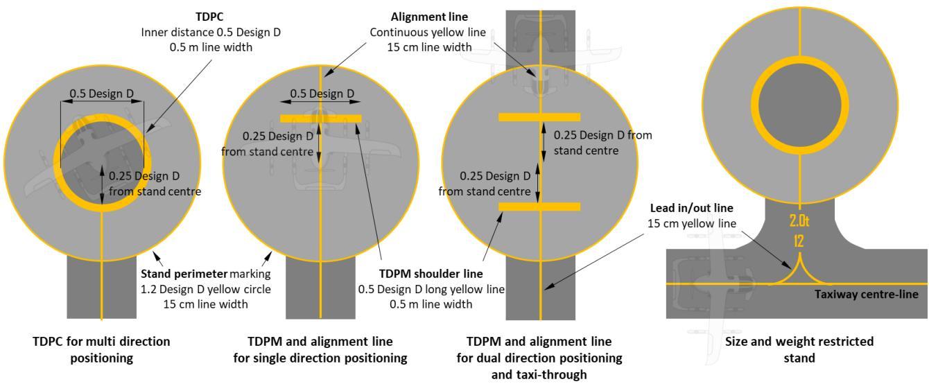
Figure 13: Stand markings
5.5 Visual Aids - Lighting
5.5.1 General
5.5.1.1 Lights and lighting systems should be installed, in accordance with the following specifications, at a vertiport intended to be used at night.
5.5.1.2 The photometrics for vertiport lights and lighting elements should be appropriate to the vertiport environment and intended operations without being visually distracting or confusing to pilots.
5.5.1.3 If the operating environment varies, lighting systems should be adjustable in order to achieve the appropriate intensity, if needed.
5.5.2 Approach lighting system
Reserved
5.5.3 Flight path alignment guidance lighting system
5.5.3.1 Flight path alignment guidance lighting system(s) (FPAGLS) should be provided at a vertiport where it is desirable and practicable to indicate available landing and/or takeoff path direction(s), as shown in Figure 14.
5.5.3.2 The flight path alignment guidance lighting system should be located in a straight line along the direction(s) of approach and/or departure path to/from the TLOF or FATO within the FATO, TLOF or protection area.
5.5.3.3 If combined with a flight path alignment guidance marking, as far as is practicable the lights should be located inside the “arrow” markings.
5.5.3.4 A flight path alignment guidance lighting system should consist of the following characteristics:
a. a row of three or more lights spaced uniformly with a total minimum distance of 6 m
b. intervals between lights should not be less than 1.5 m and should not exceed 3 m
c. where space permits, there should be 5 lights. (See Figure 14)
d. be steady omnidirectional inset white lights.
5.5.3.5 Where a FPAGLS is for an approach only or departure only (but not both), additional lights can be added to indicate the desired direction. These lights should have the following characteristics:
a. a barrette of 3 lights, spaced 0.5 m apart
b. perpendicular to the line of the FPAGLS
c. located centrally between the last and second to last light to form an arrow-head (see Figure 14).
5.5.3.6 The system should allow an adjustment of light intensity to meet the prevailing conditions and to balance the flight path alignment guidance lighting system with other vertiport lights and general lighting that may be present around the vertiport.

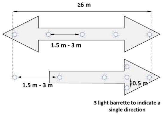

Note - Markings have been shaded to emphasise the lighting
Figure 14: Flight path alignment guidance lights and arrangement for aiming point lights
5.5.4 Visual alignment guidance system Reserved
5.5.5 Visual approach slope indicator Reserved
5.5.6 FATO Perimeter lights
5.5.6.1 Where a FATO is established at a vertiport for use at night, the FATO should be provided with perimeter lights, as shown in Figures 15a, 15b and 15c.
5.5.6.2 FATO perimeter lights should be placed along, outside and within 0.3 m of the edge(s) of the FATO. The lights should be uniformly spaced as follows:
a. for a straight edge, a light at the end of each edge, then with lights evenly spaced at not more than 5 m apart
b. for a curved edge, lights evenly spaced and not more than 5 m apart.
5.5.6.3 FATO perimeter lights should have the following characteristics:
a. be fixed omnidirectional lights
b. white in colour
c. be inset where the FATO and TLOF are collocated and accessed by a taxiway, otherwise, be not more than 25 cm in height.
5.5.7 Aiming point lights
5.5.7.1 Where an aiming point marking is provided at a vertiport intended for use at night, aiming point lights should be provided, as shown in Figures 14 and 15c.
5.5.7.2 Aiming point lights should be collocated with the aiming point marking.
5.5.7.3 Aiming point lights should form a pattern of at least six omnidirectional white lights as shown in Figure 14 and 15c. The lights should be inset when a light extending above the FATO could endanger VCA operations.
5.5.8 TLOF lighting system
5.5.8.1 Where a TLOF is established at a vertiport intended for use at night, the TLOF perimeter should be lit, unless the TLOF is centrally located within the FATO, the TDPC is lit, or is located within a stand lit by floodlighting, as shown in Figures 15a and 15c.
5.5.8.2 The lighting for the TLOF should consist of:
a. TLOF perimeter lights
and/or
b. TDPC lighting segments
TLOF - perimeter lights
5.5.8.3 TLOF perimeter lights should be placed along, outside and within 0.3 m of the edges of the TLOF. The lights should be uniformly spaced as follows:
a. for a straight edge, a light at the end of each edge, then with lights evenly spaced between at not more than 3 m apart
b. for a curved edge, light evenly spaced and not more than 3 m apart.
5.5.8.4 TLOF perimeter lights should have the following characteristics:
a. be fixed omnidirectional lights
b. green in colour
c. be inset where the TLOF is accessed by a taxiway, otherwise, be not more than 5 cm in height.
TLOF - lighting segments
Reserved
TDPC - lighting segments
5.5.8.5 Lighting segments should have the following characteristics:
a. a width no larger than the marking it defines
b. a frame the same colour as the marking it defines.
c. have a finish that does not reduce surface friction of the TLOF.
5.5.8.6 Lighting segments, where provided to identify the TDPC as shown in Figure 15b, should have the following characteristics:
a. a total length of lighting segments, in a pattern, of between 50% and 75% of the length of the pattern
b. be evenly spaced with gaps between lighting segments of not less than 0.5 m
c. be placed within the marking designating the TDPC such that the lighting segments are within 10 cm of the inner edge of the marking
d. show yellow light.
5.5.9 Vertiport identification marking lighting
5.5.9.1 The vertiport identification marking may be lit.
5.5.9.2 Vertiport identification marking lighting should not adversely impact the TLOF surface.
5.5.10 VCA taxiway/air taxi-route lighting
5.5.10.1 Where a taxi-route is established at a vertiport intended for use at night, the taxi-route centreline should be lit.
5.5.10.2 Taxi-route lights should be placed along the taxiway centreline spaced at intervals sufficient to provide directional guidance to pilots.
5.5.10.3 Taxiway lighting should be yellow, and air taxi-route lighting should be alternating yellow and green, as shown in Figure 15c.
5.5.11 VCA stand lighting
5.5.11.1 VCA stand lighting should be provided on a stand intended to be used at night by VCA.
5.5.11.2 VCA stand lighting floodlights as shown in Figure 15c should be located so as to provide adequate illumination, with a minimum of glare to the pilot of an aircraft in flight and on the ground, and to personnel on the stand. The arrangement and aiming of floodlights should be such that a VCA stand receives light from two or more directions to minimise shadows.
5.5.11.3 The spectral distribution of stand floodlights should be such that the colours used for surface and obstacle markings can be correctly identified.
5.5.11.4 Horizontal and vertical illuminance should be sufficient to ensure that visual cues are discernible for required manoeuvring and positioning, and essential operations round the VCA can be performed expeditiously without endangering personnel or equipment.

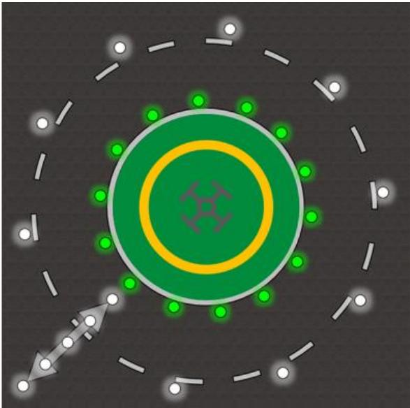
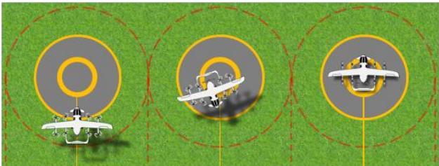
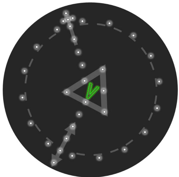
Figure 15a: Vertiport lighting examples
Figure 15a demonstrates an example of marking a FATO that includes:
– FATO white omnidirectional lights <5 m apart
– TLOF green omnidirectional perimeter lights <3 m apart
– TDPC – in this case not lit
– flight path alignment guidance lighting of 5 white omnidirectional lights.
Note: The image is an example only and does not limit possible vertiport lighting combinations.

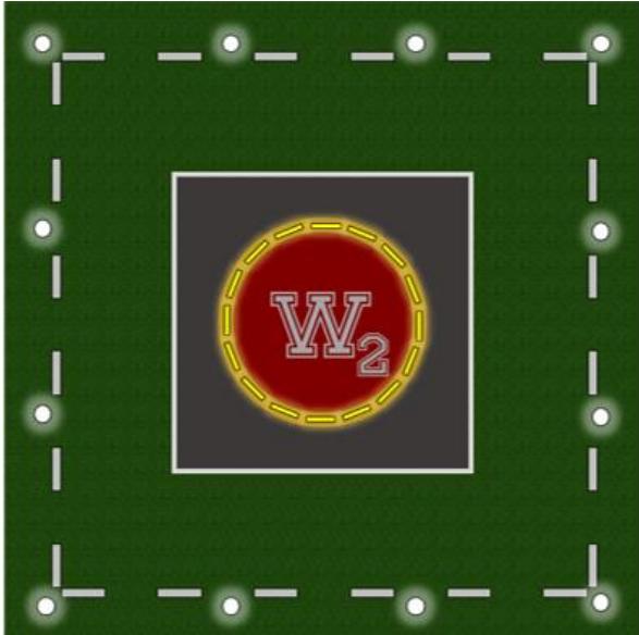
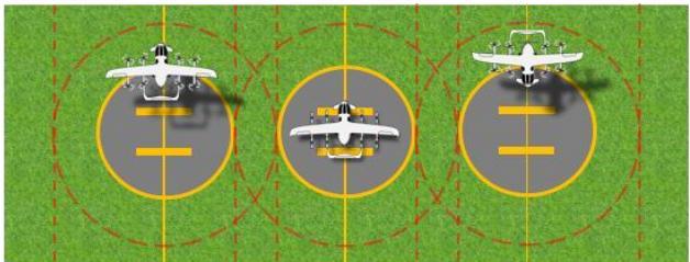
Figure 15b: Vertiport lighting examples
Figure 15b demonstrates an example of marking a FATO that includes:
– FATO white omnidirectional lights <5 m apart
– TLOF – not lit as the TDPC is lit
– TDPC Yellow panel lights.
Note: The image is an example only and does not limit possible vertiport lighting combinations.

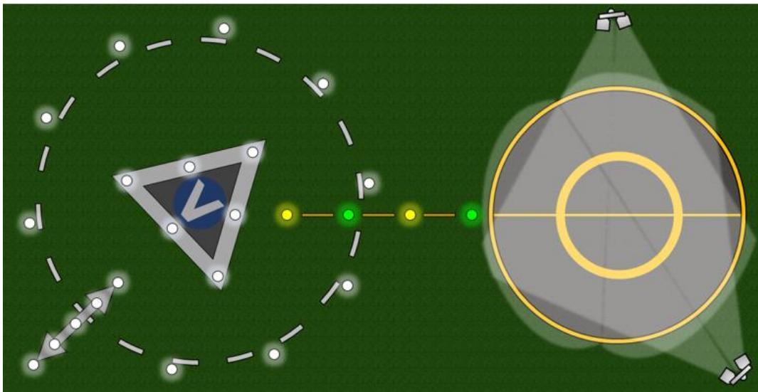
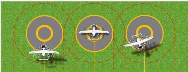
Figure 15c: Vertiport lighting examples
Figure 15c demonstrates an example of lighting a FATO that includes:
– aiming point with 6 white omnidirectional lights
– FATO white omnidirectional lights evenly spaced <5 m apart
– flight path alignment guidance lights of 5 white omnidirectional lights
– air-taxi route markers – yellow/green omnidirectional lights
– stand TLOF & TDPM – stand floodlights
– vertiport identification which is not lit.
Note: The image is an example only and does not limit possible vertiport lighting combinations.
5.6 Machine-readable visual aids
Nothing in the specifications above preclude the use of machine-readable aids, such as QR codes, being used for aircraft or vehicle guidance on a vertiport.