MinerU OCR: ICAO Annex 14 Volume II
International Standards and Recommended Practices

Annex 14 to the Convention on International Civil Aviation
Aerodromes
Volume II
Heliports
This edition incorporates all amendments
adopted by the Council prior to 5 March 2009
and supersedes, on 19 November 2009, all previous editions of Annex 14, Volume Il.
For information regarding the applicability
of Standards and Recommended Practices,
see Foreword and the relevant clauses in each chapter.
Third Edition
July 2009
International Civil Aviation Organization
International Standards
and Recommended Practices

Annex 14
to the Convention on
International Civil Aviation
Aerodromes
Volume II
Heliports
This edition incorporates all amendments adopted by the Council prior to 5 March 2009 and supersedes, on 19 November 2009, all previous editions of Annex 14, Volume II.
For information regarding the applicability of the Standards and Recommended Practices, see Foreword and the relevant clauses in each' chapter.
Third Edition July 2009
International Civil Aviation Organization
Published in separate English, Arabic, Chinese, French, Russian and Spanish editions by the
INTERNATIONAL CIVIL AVIATION ORGANIZATION
999 University Street, Montréal, Quebec, Canada H3C 5H7
For ordering information and for a complete listing of sales agents and booksellers, please go to the ICAO website at www.icao.int
First edition 1990
Second edition 1995
Third edition 2009
Annex 14, Volume I, Heliports
Order Number: AN14-2
ISBN 978-92-9231-330-2
©ICAO 2009
All rights reserved. No part of this publication may be reproduced, stored in a retrieval system or transmitted in any form or by any means, without prior permission in writing from the International Civil Aviation Organization.
AMENDMENTS
Amendments are announced in the supplements to the Catalogue of ICAO Publications; the Catalogue and its supplements are available on the ICAO website at www.icao.int. The space below is provided to keep a record of such amendments.
RECORD OF AMENDMENTS AND CORRIGENDA
| AMENDMENTS | CORRIGENDA | |||||||||
| No. | Dateapplicable | Dateentered | Enteredby | No. | Dateof issue | Dateentered | Enteredby | |||
| 1-4 | Incorporated in this edition | |||||||||
TABLE OF CONTENTS
Page
Abbreviations and symbols; manuals . … …… (vii)
FOREWORD.. …… (ix)
CHAPTER 1. General.…… 1-1
1.1 Definitions... … …… 1-1
1.2 Appicabiity … 1-3
1.3 Common reference ystem … 1-4
1.3.1 Horizontal reference yst … 1-4
1.3.2 Vertical reference system. 1-4
1.3.3 Temporal reference system. 1-4
CHATE a…… 2-1
2.1 Aeronautical data … ……… 2-1
2.2 Heliport reference point . … …… … 2-2
2.3 Heliport elevation. 2-2
2.4 Heliport dimensions and related information… 2-2
2.5 Declared distances.… 2-3
2.6 Coordination between aeronautical information services and heliport authorities.. 2-4
3-1
3.1 Surface-level heliports …… ……… 3-1
Final approach and take-off areas . 3-1
Helicopter clearways . 3-2
Touchdown and ift-off areas … … 3-2
Safety areas …… 3-2
Helicopter ground taxiways and ground taxi-routes … 3-4
Helicopter air taxiways and air taxi-routes. … 3-5
Air transit route . ………… 3-6
Aprons... 3-6
Location of a final approach and take-off area in relation to a runway or taxiway …… 3-9
3.2 Elevated heliports.. …… 3-9
Final approach and take-off areas and touchdown and lift-off areas …… 3-10
Helicopter clearways.… ……… 3-10
Touchdown and lift-off areas …… … … 3-11
Safety areas … ………… 3-11
Helicopter ground taxiways and ground taxi-route …… 3-12
Helicopter air taxiways and air taxi-routes . 3-13
Aprons.. … 3-13
3.3 Helidecks. …… 3-14
— Final approach and take-off areas and touchdown and ift-off areas …… 3-14
3.4 Shipboard heliports … 3-15
—Final approach and take-off areas and touchdown and ift-off areas …… 3-15
HAPTER 4.Obstacle restriction and removal 4-1
4.1 Obstacle limitation surfaces and sectors …… … 4-1
Approach surface …… 4-1
Transitional surface… 4-1
Inner horizontal surface …… … 4-2
Conical surface … 4-2
Take-off climb surface 4-3
Obstacle-free sector/surface—helidecks … 4-3
Limited obstacle surface—helidecks … 4-4
4.2 Obstacle limitation requirements … …………… 4-4
Surface-eeleipr 4-4
Elevated heliports. 4-5
Helidecks … 4-6
Shipboard heliports . 4-6
Non-purpose-built heliports . 4-7
HAPTER 5. Visual aid …… 5-1
5.1 Indicators. … 5-1
5.1.1 Wind direction indicator… 5-1
5.2 Markings and markers.…… …… 5-2
5.2.1 Winching area marking… … 5-2
5.2.2 Heliport identification marking…… 5-2
5.2.3 Maximum allowable mass marking.… 5-3
5.2.4 Maximum allowable D-value marking… 5-4
5.2.5 Final approach and take-off area marking or marker.… …… 5-4
5.2.6 Final approach and take-off area designation marking … …… 5-6
5.2.7 Aiming point marking…… 5-6
5.2.8 Touchdown and ift-of rea marking… 5-7
5.2.9 Touchdown/positioning marking……… …… 5-8
5.2.10 Heliport name marking…… … 5-8
5.2.11 Helideck obstacle-free sector marking. 5-9
5.2.12 Helideck surface marking ……… … 5-9
5.2.13 Helideck prhibited anding sector marking… 5-9
5.2.14 Marking for taxiways.… 5-10
5.2.15 Air taxiway markers. ………… 5-10
5.2.16 Air transit route markers. 5-10
5.3 Lights… …… 5-12
5.3.1 General.. 5-12
5.3.2 Heliport beacon.…… 5-13
5.3.3 Approach ghting sstem … 5-15
5.3.4 Visual alignment guidance ystem… 5-16
5.3.5 Visual apprach pe indicator…… 5-18
5.3.6 Final approach and take-off area lights . 5-22
5.3.7 Aiming point lights . . 5-22
5.3.8 Touchdown and ift-off area ighting system.… 5-23
5.3.9 Winching area floodlighting.…… 5-25
5.3.10 Taxiway lights .. 5-25
5.3.11 Visual aids for denoting obstacles …. 5-25
5.3.12 Floodighting of obstacles… 5-26
CHAPTER 6. Heliport services … 6-1
6.1 Rescue and fire fighting…… 6-1
General. 6-1
Level of protection to be provided. …………………………………… 6-1
Extinguishing agents.. …… 6-2
Rescue equipment.. 6-3
Response time … 6-3
APPENDIX 1.Aernautical data qality reqirments…… APP 1-1
ABBREVIATIONS AND SYMBOLS (used in Annex 14, Volume II)
Abbreviations
| cd | Candela | RD | Diameter of the largest rotor |
| cm | Centimetre | RTODAH | Rejected take-off distance available |
| D | Helicopter greatest overall dimension | S | Second |
| FATO | Final approach and take-off area | TLOF | Touchdown and lift-off area |
| ft | Foot | TODAH | Take-off distance available |
| HAPI | Helicopter approach path indicator | VMC | Visual meteorological conditions |
| Hz | Hertz | ||
| IMC | Instrument meteorological conditions | ||
| kg km/h | Kilogram Kilometre per hour | Symbols | |
| kt | Knot | ||
| L | Litre | o | Degree |
| LDAH | Landing distance available | = | Equals |
| L/min | Litre per minute | % | Percentage |
| m | Metre | 土 | Plus or minus |
Aerodrome Design Manual (Doc 9157)
Part 1 — Runways
Part 2 — Taxiways, Aprons and Holding Bays
Part 3 — Pavements
Part 4 — Visual Aids
Part 5 — Electrical Systems
Part 6 — Frangibility
Airport Planning Manual (Doc 9184)
Part 1 — Master Planning
Part 2 — Land Use and Environmental Control
Part 3 — Guidelines for Consultant/Construction Services
Airport Services Manual (Doc 9137)
Part 1 — Rescue and Fire Fighting
Part 2 — Pavement Surface Conditions
Part 3 — Bird Control and Reduction
Part 4 — Fog Dispersal (withdrawn)
Part 5 — Removal of Disabled Aircraft
Part 6 — Control of Obstacles
Part 7 — Airport Emergency Planning
Part 8 — Airport Operational Services
Part 9 — Airport Maintenance Practices
Heliport Manual (Doc 9261)
Manual of Surface Movement Guidance and Control Systems (SMGCS) (Doc 9476)
Manual on the ICAO Bird Strike Information System (IBIS) (Doc 9332)
Stolport Manual (Doc 9150)
FOREWORD
Historical background
Standards and Recommended Practices for aerodromes were first adopted by the Council on 29 May 1951 pursuant to the provisions of Aricle 37 of the Convention on International Civil Aviation (Chicago 1944) and designated as Annex 14 to the Convention. The document containing these Standards and Recommended Practices is now designated as Annex 14, Volume I to the Convention. In general, Volume I addresses planning, design and operations of aerodromes but is not specifically applicable to heliports.
Therefore, Volume I is being introduced as a means of including provisions for heliports. Proposals for comprehensive Standards and Recommended Practices covering all aspects of heliport planning, design and operations have been developed with the assistance of the ANC Visual Aids Panel and the ANC Helicopter Operations Panel.
Table A shows the origin of the provisions in this volume, together with a ist of the principal subjects involved and the dates on which the Annex was adopted by the Council, when it became effective and when it became applicable.
Action by Contracting States
Notification of differences. The attention of Contracting States is drawn to the obligation imposed by Article 38 of the Convention by which Contracting States are required to notify the Organization of any differences between their national regulations and practices and the International Standards contained in this Anex and any amendments thereto. Contracting States are invited to extend such notification to any differences from Recommended Practices contained in this Anex and any amendments theretowhen the notfication of uch diferences is iportant for the safey of air navigation.Furter, Contacti States are invited to keep the Organization currently informed of any diferences which may subsequently ocur, or of the withdrawal f any diferences previously noified.A specified request for notifiation of iffrences wil e sent toContacting States immediately after the adoption of each amendment to this Annex.
The attention of States is also drawn to the provisions of Annex 15 related to the publication of differences between their national regulations and practices and the related ICAO Standards and Recommended Practices through the Aeronautical Information Service, in addition to the obligation of States under Article 38 of the Convention.
Promulgation of information. The establishment and withdrawal of and changes to faciliies, services and procedures affecting airraft operations provided in accordance with the Standards and Recommended Practices specified in this Annex should be notified and take effect in accordance with the provisions of Annex 15.
Status of Annex components
An Annex is made up of the following component parts, not allof which, however, are necessaril found i every Annex; they have the status indicated:
1.— Material comprising the Annex proper:
a) Standards and Recommended Practices adopted by the Council under the provisions of the Convention. They are defined as follows:
Standard: Any specification for physical characteristics, configuration, matériel, performance, personnel or procedure, the uniform application of which is recognized as necessary for the safety or regularity of international air navigation and to which Contracting States wil conform in accordance with the Convention; in the event of impossibility of compliance, notification to the Council is compulsory under Article 38.
Recommended Practice: Any specification for physical characteristics, configuration, matériel, performance, personnel or procedure, the uniform application of which is recognized as desirable in the interest of safety, regularity or efficiency of international air navigation, and to which Contracting States wil endeavour to conform in accordance with the Convention.
b) Appendices comprising material grouped separately for convenience but forming part of the Standards and Recommended Practices adopted by the Council.
c) Definitions of terms used in the Standards and Recommended Practices which are not self- explanatory in that they do not have accepted dictionary meanings. A definition does not have independent status but is an essential part of each Standard and Recommended Practice in which the term is used, since a change in the meaning of the term would affect the specifications.
d) Tables and Figures which add to or ilustrate a Standard or Recommended Practice and which are referred to therein, form part of the associated Standard or Recommended Practice and have the same status.
2.— Material approved by the Council for publication in association with the Standards and Recommended Practices:
a) Forewords comprising historical and explanatory material based on the action of the Council and including an explanation of the obligations of States with regard to the application of the Standards and Recommended Practices ensuing from the Convention and the Resolution of Adoption.
b) Introductions comprising explanatory material introduced at the beginning of parts, chapters or sections of the Annex to assist in the understanding of the application of the text.
c) Notes included in the text, where appropriate, to give factual information or references bearing on the Standards or Recommended Practices in question, but not constituting part of the Standards or Recommended Practices.
d) Attachments comprising material supplementary to the Standards and Recommended Practices, or included as a guide to their application.
Selection of language
This Annex has been adopted in six anguages— English, Arabic, Chinese, French, Rusian and Spanish. Each Contracting State is requested to select one of those texts for the purpose of national implementation and for other effects provided for i the Convention, either through direct use or through translation into its own national language, and to notify the Organization accordingly.
Editorial practices
The following practice has been adhered to in order t indicate at a glance the status of each statement: Standards have been printed in light face roman; Recommended Practices have been printed in ight face italics, the status being indicated by the prefix Recommendation; Notes have been printed in ight face italics, the status being indicated by the prefix Note.
The following editorial practice has been followed i the writing of specifications: for Standards the operative verb "shal" is used, and for Recommended Practices the operative verb "should' is used.
The units of measurement used in this document are in acordance with the International System of Units (SI) as specified in Annex 5 to the Convention on International Civil Aviation. Where Annex 5 permits the use of non-SI alternative units these are shown in parentheses following the basic units.Where two sets of units are quoted it must not be assumed that te pairs of values are equal and interchangeable.It may, however, be inferred that an equivalent level f safety is achieved when either set of units is used exclusively.
Any reference to a portion of this document, which is identified by a number and/or tite, includes ll subdivisions of that portion.
Table A. Amendments to Annex 14, Volume II
| Amendment | Source(s) | Subject(s) | Adopted Effective Applicable |
| 1st Edition | Fourth Meeting of the ANC Helicopter Operations Panel; Eleventh Meeting of the ANC Visual Aids Panel and Secretariat | Physical characteristics; obstacle limitation surfaces; visual aids for visual meteorological conditions; rescue and fire fighting services. | 9 March 1990 30 July 1990 15 November 1990 |
| 1 (2nd Edition) | Twelfth Meeting of the ANC Visual Aids Panel and Secretariat | Standard geodetic reference system (WGS-84); frangibility; visual aids for helicopter non-precision approaches; and visual alignment guidance system. | 13 March 1995 24 July 1995 9 November 1995 |
| 2 | Air Navigation Commission | Aeronautical databases and vertical component of the World Geodetic System — 1984 (WGS-84). | 21 March 1997 21 July 1997 6 November 1997 |
| 3 | Fourteenth Meeting of the ANC Visual Aids Panel and Secretariat | Definitions of calendar, datum, Gregorian calendar and obstacle; common reference systems; heliport dimensions and related information; touchdown and lift-off area lighting system; Appendix 1 — Aeronautical Data Quality Requirements. | 27 February 2004 12 July 2004 25 November 2004 |
| 4 (3rd Edition) | First Meeting of the Aerodromes Panel | Introductory note; definitions of air transit route, declared distances, dynamic load-bearing surface, final approach and take-off area, helicopter air taxiway, helicopter clearway, helicopter ground taxiway, helicopter stand, helideck, obstacle, protection area, rejected take-off area, shipboard heliport, static load-bearing surface, taxi-route, touchdown and lift-off area, winching area; applicability; physical characteristics for surface-level heliports, elevated heliports, helidecks, and shipboard heliports; obstacle limitation surfaces and sectors and requirements for helidecks and shipboard heliports; winching area marking; heliport identification marking; maximum allowable mass marking; maximum allowable D-value marking; touchdown and lift-off area marking; touchdown/positioning marking; helideck obstacle-free sector marking; helideck | 4 March 2009 20 July 2009 19 November 2009 |
INTERNATIONAL STANDARDS AND RECOMMENDED PRACTICES
CHAPTER 1. GENERAL
Introductory Note.—Annex 14, Volume I, contains Standards and Recommended Practices (specifications) that prescribe the physical characteristics and obstacle limitation surfaces to be provided for at heliports, and certain faciliies and technical services normally provided at a heliport It is not intended that these speifications limit or regulate the operation of an aircraf.
When designing a heliport, the critical design helicopter, having the largest set of dimensions and the greatest maximum take-off mass (MTOM) the heliport is intended to serve, would need to be considered.
It is to be noted that provisions for helicopter flight operations are contained in Annex 6, Part III.
1.1 Definitions
When the follwing terms are used in this volume, they have the meanings given below. Annex 14, Volume I, contains definitions for those terms which are used in both volumes.
Accuracy. A degree of conformance between the estimated or measured value and the true value.
Note.— For measured positional data, the accuracy is normally expressed in terms of a distance from a stated position within which there is a defined confidence of the true position falling.
Air transit route. A defined route for the air transiting of helicopters.
Calendar. Discrete temporal reference system that provides the basis for defining temporal position to a resolution of one day (ISO 19108*).
Cyclic redundancy check (CRC). A mathematical algorithm applied to the digital expression of data that provides a level of assurance against loss or alteration of data.
Data quality. A degree or level of confidence that the data provided mee the requirements of the data user i terms of acuracy, resolution and integrity.
Datum. Any quantity or set of quantities that may serve as a reference or basis for the calculation of other quantities (ISO 19104**).
Declared distances — heliports.
a) Take-of distance available (TODAH). The length of the FATO plus the length of helicopter clearway (if provided) declared available and suitable for helicopters to complete the take-off.
b) Rejected take-off distance available (RTODAH). The length of the FATO declared available and suitable for helicopters operated in performance class 1 to complete a rejected take-off.
c) Landing distance available (LDAH). The length of the FATO plus any aditional area declared available and suitable for helicopters to complete the landing manoeuvre from a defined height.
Dynamic load-bearing surface. A surface capable of supporting the loads generated by a helicopter conducting an emergency touchdown on it.
Elevated heliport. A heliport located on a raised structure on land.
Ellipsoid height Geodetic height). The height related to the reference ellpsoid, measured along the ellipsoidal outer normal through the point in question.
Final approach and take-off area (FATO). A defined area over which the final phase of the approach manoeuvre to hover or landing is completed and from which the take-off manoeuvre is commenced. Where the FATO is to be used by helicopters operated in performance class 1, the defined area includes the rejected take-of area available.
Geodetic datum. A minimum set of parameters required to define lcation and orientation of the local reference system with respect to the global reference system/frame.
Geoid. The equipotential surface in the gravity field of the Earth which coincides with the undisturbed mean sea level (MSL) extended continuously through the continents.
Note.The geoid is irregular in shape because of local gravitational disturbances (wind ides, salinity, current, etc.) and the direction of gravity is perpendicular to the geoid at every point.
Geoid undulation. The distance of the geoid above (positive) or below (negative) the mathematical reference ellipsoid.
Note.— In respect to the World Geodetic System — 1984 (WGS-84) defined llipsoid, the difference between the WGS-84 ellipsoidal height and orthometric height represents WGS-84 geoid undulation.
Gregorian calendar. Calendar in general use; first introduced in 1582 to define a year that more closely approximates the tropical year than the Julian calendar (ISO 19108***).
Note.— In the Gregorian calendar, common years have 365 days and leap years 366 days divided into twelve sequential months.
Helicopter air taxiway. A defined path on the surface established for the air taxing of helicopters.
Helicopter clearway. A defined area on the ground or water, selected and/or prepared as asuitable area over which a helicopter operated in performance class 1 may accelerate and achieve a specific height.
Helicopter ground taxiway. A ground taxiway intended for the ground movement of wheeled undercarriage helicopters.
Helicopter stand. An aircraft stand which provides for parking a helicopter and where ground taxi operations are completed or where the helicopter touches down and lifts off for air taxi operations.
Helideck.A heliport located on an offshore structure such as an exploration or production platform used for the exploitation of oil or gas.
Heliport. An aerodrome or a defined area on a structure intended to be used wholly or in part for the arrival, departure and surface movement of helicopters.
Integrity (aeronautical ata).A degree of assurance that an aeronautical data and its value has not been lost nor ltered since the data origination or authorized amendment.
Obstacle. All fixed (whether temporary or permanent) and mobile objects, or parts thereof, that:
a) are located on an area intended for the surface movement of aircraft; or
b) extend above a defined surface intended to protect aircraft in flight; or
c) stand outside those defined surfaces and that have been assessed as being a hazard to air navigation.
Orthometric height. Height of a point related to the geoid, generally presented as an MSL elevation.
Protection area. An area within a taxi-route and around a helicopter stand which provides separation from objects, the FATO, other taxi-routes and helicopter stands, for safe manoeuvring of helicopters.
Rejected take-of area. A defined area on a heliport suitable for helicopters operating in performance class 1 to complete a rejected take-off.
Safety area. A defined area on a heliport surrunding the FATO which is free of obstacles, other than those required for air navigation purposes, and intended to reduce the risk of damage to helicopters accidentally diverging from the FATO.
Shipboard heliport. A heliport located on a ship that may be purpose or non-purpose-built. A purpose-buit shipboard heliport is one designed specifically for helicopter operations.A non-purpose-built shipboard heliport s one that utilizes an area of the ship that is capable of supporting a helicopter but not designed specifically for that task.
Static load-bearing surface. A surface capable of supporting the mass of a helicopter situated upon it.
Station declination. An alignment variation between the zero degreeradial of a VOR and true north, determined at the time the VOR station is calibrated.
Surface-level heliport. A heliport located on the ground or on the water.
Taxi-route. A defined path established for the movement of helicopters from one part of a heliport to another. A taxi-route includes a helicopter air or ground taxiway which is centred on the taxi-route.
Touchdown and lift-off area (TLOF). An area on which a helicopter may touch down or lift off.
Winching area. An area provided for the transfer by helicopter of personnel or stores to or from a ship.
1.2Applicability
Note — The dimensions discused in this Annex are based on consideration of single-main-rotor helicopters. For tandem-rotor helicopters the heliport design wil be based on a case-by-case review of the specific models using the basic requirement for a safety area and protection areas specified in this Annex.
1.2.1 The interpretation of some of the specifications in the Annex expresly requires the exercising of discretion, the taking of a decision or the performance of a function by the appropriate authority. In other specifications, the expression appropriate authority does not actually appear although it inclusion is implied. In both cases, the responsibility for whateer determination or action is necessary shall rest with the State having jurisdiction over the heliport.
1.2.2 The specifications in Annex 14, Volume I, shall apply to all heliports intended to be used by helicopters in international civil aviation. They shall apply equally to areas for the exclusive use of helicopters at an aerodrome primarily meant for the use of aeroplanes. Where relevant, the provisions of Annex 14, Volume I, shll apply to the helicopter operations being conducted at such an aerodrome.
1.2.3 Unless otherwise specified, the specification for a colour referred to within this volume shall be that contained in Appendix 1 to Annex 14, Volume I.
1.3 Common reference systems
1.3.1 Horizontal reference system
1.3.1.1 World Geodetic System —1984 (WGS-84) shal be used as the horizontal (geodetic) reference system. Reported aeronautical geographical cordinates (indicating latitude and longitude) shall be expressed in terms of the WGS-84 geodetic reference datum.
Note.— Comprehensive guidance material concerning WGS-84 is contained in the World Geodetic System — 1984 (WGS-84) Manual (Doc 9674).
1.3.2 Vertical reference system
1.3.2.1 Mean sea level (MSL) datum, which gives the relationship of gravity-related height (elevation) to a surface known as the geoid, shall be used as the vertical reference system.
Note 1.— The geoid globally most losely approximates MSL. It is defined as the equipotential urface in the gravity feld of the Earth which coincides with the undisturbed MSL extended continuously through the continents.
Note 2.—Gravity-related heights (elevations) are also referred to as orthometric heights while distances of points above the ellipsoid are referred to as ellipsoidal heights.
1.3.3 Temporal reference system
1.3.3.1 The Gregorian calendar and Coordinated Universal Time (UTC) shall be used as the temporal reference system.
1.3.3.2 When a diffrent temporal reference system is used, this shal be indicated in GEN 2.1.2 of the Aeronautical Information Publication (AIP).
CHAPTER 2. HELIPORT DATA
2.1Aeronautical data
2.1.1 Determination and reporting of heliport-related aeronautical data shall be in accordance with the accuracy and integrity requirements set forth in Tables A1-1 to A1-5 contained in Appendix 1 while aking into account the established quality system procedures. Accuracy equirements for aeronautical data are based upon a 95 per cent confidence level and in that espect, three types of positional data shall be identified: surveyed points (e.g. FATO threshold), calculated points (mathematical calculations f thekw sureyed points of points in space, fixes) and declared pints e. figh iforation region bundary points).
Note. — Specifications governing the quality system are given in Annex 15, Chapter 3.
2.1.2 Contracting States shal ensure that integrity of aeronautical data is maintained throughout the data process from survey/origin to the next intended user. Aeronautical data integrity requirements shall be based upon the potential risk resulting from the coruption of data and upon the use to which the data item is put. Consequently, the following clasifications and ata integrity levels shall apply:
a) critical data, integrity level $I \times I O ^ { - 8 . }$ there is a high probability when using corrupted critical data that the continued safe flight and landing of an aircraft would be severely at risk with the potential for catastrophe;
b) essential data, integrity level $I \times I O ^ { - 5 } ;$ there is a low probability when using corrupted essential data that the continued safe flight and landing of an aircraft would be severely at risk with the potential for catastrophe; and
c) routine data, integrity level $I \times I O ^ { - 3 } ;$ there is a very low probability when using corrupted routine data that the continued safe flight and landing of an aircraft would be severely at risk with the potential for catastrophe.
2.1.3 Protection of electronic aeronautical data while stored or in transit shall be totally monitored by the cyclic redundany check CRC). To achieve protection of the integrity level of critical and essential aeronautical data as claified in 2.1.2, a 32- or 24-bit CRC algorithm shall apply respectively.
2.1.4 Recommendation.—To achieve protection of the integrity level of routine aeronautical data as clasified in 2.1.2 a 16-bit CRC algorithm should apply.
Note.— Guidance material on the aeronautical data quality requirements (accuracy, resolution, integrity, protection and traceability) is contained in the World Geodetic System — 1984 (WGS-84) Manual (Doc 9674). Supporting material in respect of the provisions of Appendix 1 related t accuracy and integrity of aeronautical data is contained in RTCA Document DO-201A and European Organization for Civil Aviation Equipment (EUROCAE) Document ED-77— Industry Requirements for Aeronautical Information.
2.1.5 Geographical cordinates indicating lattude and longitude shall be determined and reported to the aeronautical information services authority in terms of the World Geodetic System—1984 (WGS-84) geodetic reference datum, identifying those geographical coordinates which have been transformed into WGS-84 coordinates by mathematical means and whose accuracy of original field work does not meet the requirements in Appendix 1, Table A1-1.
2.1.6 The order of accuracy of the field work shall be such that the resulting operational navigation data for the phases of flight wil e within te maximum deviations, with respect to an appropriate referenceframe, as indicated in the tables contained in Appendix 1.
2.1.7 In addition to the elevation (referenced to mean sea level) of the specific surveyed ground positions at heliports, geoid undulation (referenced to the WGS-84 elipsoid) for those positions as indicated in Appendix 1 shall be determined and reported to the aeronautical information services authority.
Note 1.—An appropriate reference frame is that which enables WGS-84 to be realized on a given heliport and with respect to which all coordinate data are related.
Note 2.— Specifications governing the publication of WGS-84 coordinates are given in Annex 4, Chapter 2, and Annex 15, Chapter 3.
2.2 Heliport reference point
2.2.1 A heliport reference point shall be established for a heliport not collocated with an aerodrome.
Note.— When the heliport is collocated with an aerodrome, the established aerodrome reference point serves both aerodrome and heliport.
2.2.2 The heliport reference point shall be located near the initial or planned geometric centre of the heliport and shall normally remain where first established.
2.2.3 The position of the heliport reference point shal e measured and reported to the aeronautical information services authority in degrees, minutes and seconds.
2.3 Heliport elevation
2.3.1 The heliport elevation and geoid undulation at the heliport elevation position shall be measured and reported to the aeronautical information services authority to the accuracy of one-half metre or foot.
2.3.2 For a heliport used by international civil aviation, the elevation of the TLOF and/or the elevation and geoid undulation of each threshold of the FATO (where appropriate) shal e measured and reported to the aeronautical information services authority to the accuracy of:
a) one-half metre or foot for non-precision approaches; and
b) one-quarter metre or foot for precision approaches.
Note.— Geoid undulation must be measured in accordance with the appropriate system of coordinates.
2.4 Heliport dimensions and related information
2.4.1 The following data shall be measured or described, as appropriate, for each facility provided on a heliport:
a) heliport type — surface-level, elevated or helideck;
b) TLOF — dimensions to the nearest metre or foot, slope, surface type, bearing strength in tonnes (1 00 kg);
c) final approach and take-off area — type of FATO, true bearing to one-hundredth of a degree, designation number (where appropriate), length, width to the nearest metre or foot, slope, surface type;
d) safety area — length, width and surface type;
e) helicopter ground taxiway, air taxiway and air transit route —designation, width, surface type;
f) apron — surface type, helicopter stands;
g) clearway — length, ground profile;
h) visual aids for approach procedures, marking and lighting of FATO, TLOF, taxiways and aprons; and
i) distances to the nearest metre or foot of localizer and glide path elements comprising an instrument anding system (ILS) or azimuth and elevation antenna of a microwave landing system (MLS) in relation to the associated TLOF or FATO extremities.
2.4.2 The geographical coordinates of the geometric centre of the TLOF and/or of each threshold of the FATO (where appropriate) sha be measured and reported t the aeronautical nformation serices authorit in degrees, minutes, seconds and hundredths of seconds.
2.4.3 The geographical cordinates of appropriate centre line points of helicopter ground taxiways, air taxiways and air transit rutes shall be measured and reported to the eronautical inforation services authority in degrees, inutes seconds and hundredths of seconds.
2.4.4 The geographical coordinates of each helicopter stand shall be measured and reported to the aeronautical information services authority in degrees, minutes, seconds and hundredths of seconds.
2.4.5 The geographical cordinates of obstacles in Area 2 (the part within the heliport boundary) and in Area 3 shall be measured and reported to the aernautical information services authority in degrees, minutes, seconds and tenths of seconds. In addition, the top elevation, type, marking and lighting (if any) of obstacles shall be reported to the aeronautical information services authority.
Note 1.— See Annex 15, Appendix 8, for graphical ilustrations of obstacle data collection surfaces and criteria used to identify obstacles in Areas 2 and 3.
Note 2.— Appendix 1 to this Annex provides requirements for obstacle data determination in Areas 2 and 3.
Note 3.— Implementation of Annex 15, provision 10.6.1.2, concerning the availability, as of 18 November 2010, of obstacle data according to Area 2 and Area 3 specifications would be facilitated by appropriate advance planning for the collection and processing of such data.
2.5 Declared distances
The following distances to the nearest metre or foot shal be declared, where relevant, for a heliport:
a) take-off distance available;
b) rejected take-off distance available; and
c) landing distance available.
2.6 Coordination between aeronautical information services and heliport authorities
2.6.1 To ensure that aeronautical information services units obtain information to enable them to provide up-to-date pre-flight information and to meet the need for in-fight information, arrangements shall be made between aeronautical information services and heliport authorities responsible for heliport services to report to the responsible aeronautical information services unit, with a minimum of delay:
a) information on heliport conditions;
b) the operational status of associated faciliies, services and navigation aids within their area of responsibility;
c) any other information considered to be of operational significance.
2.6.2 Before introducing changes to the air navigation system, due account shall be taken by the services responsible for such changes of the time needed by the aeronautical information service for the preparation, production and issue of relevant material for promulgation. To ensure timely provision of the information to the aeronautical information service, close coordination between those services concerned is therefore required.
2.6.3 Of a particular importance are changes to aeronautical information that affect charts and/or computer-based navigation systems which qulify to be notified by the aeronautical information regulation and control (AIRAC) system, as specifie in Aex 15, Chapter and Appendix4. The predetermined, iternationll agreed ARAC efective dates i dition to 14 days postage time shall be observed by the responsible heliport services when submiting the raw information/data to aeronautical information services.
2.6.4 The heliport services responsible for the provision of raw aeronautical information/data to the aeronautical information services shall do that while taking into account accuracy and integrity requirements for aeronautical data as specified in Appendix 1 to this Annex.
Note 1.— Specifications for the issue of a NOTAM and SNOWTAM are contained in Annex 15, Chapter 5, and Appendices 6 and 2, respectively.
Note 2.—The AIRAC information is distributed by the AIS at least 42 days in advance of the AIRAC effective dates with the objective of reaching recipients at least 28 days in advance of the effective date.
Note 3.— The schedule of the predetermined internationally agreed AIRAC common effective dates at intervals of 28 days, including 19 November 2009, and guidance for the AIRAC use are contained in the Aeronautical Information Services Manual (Doc 8126, Chapter 2, 2.6).
CHAPTER 3. PHYSICAL CHARACTERISTICS
3.1 Surface-level heliports
Note 1.—The following specifications are for land-based heliports only. Where a water helipor is being considered, the appropriate authority may establish suitable criteria.
Note 2.— The dimensions of the taxi-routes and helicopter stands include a protection area.
Final approach and take-off areas
3.1.1 A surface-level heliport shall be provided with at least one final approach and take-off area (FATO).
Note.—A FATO may be located on or near a runway strip or taxiway strip.
3.1.2 A FATO shall be obstacle free.
3.1.3 The dimensions of a FATO shall be:
a) where intended to be used by helicopters operated in performance clas 1, as prescribed in the helicopter fight manual (HFM) except that, in the absence of width specifications, the width shall be not less than the greatest overall dimension (D) of the largest helicopter the FATO is intended to serve;
b) where intended to be used by helicopters operated in performance class 2 or 3, of sufficient size and shape to contain an area within which can be drawn a circle of diameter not less than:
-
1 D of the largest helicopter when the maximum take-off mass (MTOM) of helicopters the FATO is intended to serve is more than 3 175 kg;
-
0.83 D of the largest helicopter when the MTOM of helicopters the FATO is intended to serve is 3 175 kg or less.
Note.— Where the term FATO is not used in the HFM, the minimum landing/take-off area specified i the HFM for the appropriate flight profile is used.
3.1.4 Recommendation.— Where intended to be used by helicopters operated in performance class 2 or 3 with MTOM of 3 175 kg or less, the FATO should be of suficient size and shape to contain an area within which can be drawn a circle of diameter not less than 1 D.
Note.—Local conditions, such as elevation and temperature, may need to be considered when determining the size of a FATO. Guidance is given in the Heliport Manual (Doc 9261).
3.1.5 The mean slope in any direction on the FATO shall not exceed 3 per cent. No portion of a FATO shal have a local slope exceeding:
a) 5 per cent where the heliport is intended to be used by helicopters operated in performance class 1; and
b) 7 per cent where the heliport is intended to be used by helicopters operated in performance class 2 or 3.
3.1.6 The surface of the FATO shall:
a) be resistant to the effects of rotor downwash;
b) be free of irregularities that would adversely affect the take-off or landing of helicopters; and
c) have bearing strength ufficient to accommodate a rejected take-off by helicopters operated in performance class 1.
3.1.7 The surface of a FATO surrounding a touchdown and lift-off area (TLOF) intended for use by helicopters operated in performance classes 2 and 3 shall be static load-bearing.
3.1.8 Recommendation.— The FAT0 should provide ground effect.
Helicopter clearways
3.1.9 When a helicopter clearway is provided, it shall be located beyond the end of the rejected take-of area available.
3.1.10 Recommendation.— The width of a helicopter clearway should not be les than that of the associated safety area.
3.1.11 Recommendation.— The ground in a helicopter clearway should not project above a plane having an upward slope of 3 per cent, the lower limit of this plane being a horizontal ine which is located on the periphery of the FATO.
3.1.12 Recommendation.— An object situated on a helicopter clearway which may endanger helicopters in the air should be regarded as an obstacle and should be removed.
Touchdown and lift-off areas
3.1.13 At least one TLOF shall be provided at a heliport.
Note 1.— The TLOF may or may not be located within the FATO.
Note 2.— Additional TLOFs may be collocated with helicopter stands.
3.1.14 The TLOF shall be of sufficient size to contain a circle of diameter of at least 0.83 D of the largest helicopter the area is intended to serve.
Note.— A TLOF may be any shape.
3.1.15 Slopes on a TLOF shal be sufficient to prevent accumulation of water on the surface of the area, but shall not exceed 2 per cent in any direction.
3.1.16 Where the TLOF is within the FATO, the TLOF shall be dynamic load-bearing.
3.1.17 Where a TLOF is collocated with a helicopter stand, the TLOF shall be static load-bearing and be capable of withstanding the traffic of helicopters that the area is intended to serve.
3.1.18 Where the TLOF is within the FATO, the centre of the TLOF shall be located not less than 0.5 D from the edge of the FATO.
Safety areas
3.1.19 A FATO shall be surrounded by a safety area which need not be solid.
3.1.20 A safety area surrounding a FATO intended to be used by helicopters operated in performance class 1 in visual meteorological conditions (VMC) shall extend outwards from the periphery of the FATO for a distance of at last 3 m or 0.25 D, whichever is greater, of the largest helicopter the FATO is intended to serve and:
a) each external side of the safety area shall be at least 2 D where the FATO is quadrilateral; or
b) the outer diameter of the safety area shall be at least 2 D where the FATO is circular.
3.1.21 A safety area surrounding a FATO intended to be used by helicopters operated in performance class 2 or 3 in visual meteorological conditions (VMC) shallextend outwards from te periphery of the FATO for a distance of at least 3 m or 0.5 D, whichever is greater, of the largest helicopter the FATO is intended to serve and:
a) each external side of the safety area shall be at least 2 D where the FATO is quadrilateral; or
b) the outer diameter of the safety area shall be at least 2 D where the FATO is circular.
3.1.22 There shal be a protected side slope rising at 45 degrees from the edge of the safety area to a distance of 10 m, whose surface shall not be penetrated by obstacles, except that when obstacles are located to one side of the FATO only, they may be permitted to penetrate the side slope surface.
3.1.23 A safety area surrounding a FATO intended to be used by helicopter operations in instrument meteorological conditions (IMC) shall extend:
a) laterally to a distance of at least 45 m on each side of the centre line; and
b) longitudinally to a distance of at least 60 m beyond the ends of the FATO.
(See Figure 3-1.)
3.1.24 No fixed object shall be permited on a safety area, except for frangible objects, which, because of their function, must be located on the area. No mobile object shall be permitted on a safety area during helicopter operations.
3.1.25 Objects whose functions require them to be located on the safety area shll not exceed a height of 25 cm when located along the edge of the FATO nor penetrate a plane originating at a height of 25 cm above the edge of the FATO and sloping upwards and outwards from the edge of the FATO at a gradient of 5 per cent.
3.1.26 Recommendation.— In the case of a FATO of diameter less than 1 D, the maximum height of the objects whose functions require them to be located on the safety area should not exceed a height of 5 cm.

Figure 3-1. Safety area for instrument FATO
3.1.27 The surface of the safety area, when solid, shallnot exceed an upward slope of 4 per cent outwards from the edge of the FATO.
3.1.28 Where applicable, the surface of the safety area sha be treated to prevent flying debris caused by rotor downwash.
3.1.29 The surface of the safety area abutting the FATO shall be continuous with the FATO.
Helicopter ground taxiways and ground taxi-routes
Note 1.—A helicopter ground taxiway is intended to permit the surface movement of a wheeled helicopter under its own power.
Note 2.— The following specifications are intended for the safety of simultaneous operations during the manoeuvring of helicopters. However, the wind velocity induced by the rotor downwash might have to be considered.
Note 3.— When a taxiway is intended for use by aeroplanes and helicopters, the provisions for taxiways for aeroplanes and helicopter ground taxiways will be taken into consideration and the more stringent requirements will be applied.
3.1.30 The width of a helicopter ground taxiway shall not be les than 1.5 times the largest width of the undercarrige (UCW) of the helicopters the ground taxiway is intended to serve (see Figure 3-2).
3.1.31 The longitudinal slope of a helicopter ground taxiway shall not exceed 3 per cent.
3.1.32 A helicopter ground taxiway shall be static load-bearing and be capable of withstanding the traffic of the helicopters the helicopter ground taxiway is intended to serve.
Figure 3-2. Ground taxi-route
3.1.33 A helicopter ground taxiway shall be centred on a ground taxi-route.
3.1.34 A helicopter ground taxi-route shall extend symmetrically on each side of the centre line for at least 0.75 times the largest overall width of the helicopters it is intended to serve.
3.1.35 No objects shall be permitted on a helicopter ground taxi-route, except for frangibl objects, which, because of their function, must be located there.
3.1.36 The helicopter ground taxiway and the ground taxi-route shall provide rapid drainage but the helicopter ground taxiway transverse slope shall not exceed 2 per cent.
3.1.37 The surface of a helicopter ground taxi-route shal be resistant to the effect of rotor downwash.
Helicopter air taxiways and air taxi-routes
Note.—A helicopter air taxiway is intended to permit the movement of a helicopter above the surface at a height normally associated with ground effect and at ground speed less than 37km/h (20 kt).
3.1.38 The width of a helicopter air taxiway shall be at least two times the largest width of the undercarriage (UCW) of the helicopters that the air taxiway is intended to serve (see Figure 3-3).
3.1.39 The surface of a helicopter air taxiway shall be suitable for an emergency landing.
3.1.40 Recommendation.— The surface of a helicopter air taxiway should be static load-bearing.
Figure 3-3. Air taxi-route
3.1.41 Recommendation.— The transverse slope of the surface of a helicopter air taxiway should not exceed 10 per cent and the longitudinal slope should not exceed 7 per cent. In any event, the slopes should not exceed the slope landing limitations of the helicopters the air taxiway is intended to serve.
3.1.42 A helicopter air taxiway shall be centred on an air taxi-route.
3.1.43 A helicopter air taxi-route shall extend symmetrically on each side of the centre line for a distance at least equal to the largest overall width of the helicopters it is intended to serve.
3.1.44 No objects shall be permitted on an air taxi-route, except for frangible objects, which, because of their function, must be located thereon.
3.1.45 The surface of an air taxi-route shall be resistant to the effect of rotor downwash.
3.1.46 The surface of an air taxi-route shall provide ground effect.
Air transit route
Note.—An air transit route is intended to permit the movement of a helicopter above the surface, normally at heights not above 30 m (100 ft) above ground level and at ground speeds exceeding 37 km/h (20 kt).
3.1.47 The width of an air transit route shall not be less than:
a) 7.0 times the argest overall width of the helicopters the air ransit route is intended to serve when the air transit route is intended for use by day only; and
b) 10.0 times the largest overall width of the helicopters the air transit route is intended to serve when the air transit route is intended for use at night.
3.1.48 Any variation in the direction of the centre line of an air transit route shal not exced 120 degrees and be designed so as not to necessitate a turn of radius less than 270 m.
Note.—It is intended that air transit routes be selected so as to permit autorotative or one-engine-inoperative landings such that, as a minimum requirement, injury to persons on the ground or water, or damage to property are minimized.
Aprons
3.1.49 The slope in any direction on a helicopter stand shall not exceed 2 per cent.
3.1.50 A helicopter tand shal be of sufficient size to contain a circle of diameter of at least 1.2 D of the largest helicopter the stand is intended to serve.
3.1.51 If a helicopter stand is used for taxi-through, the minimum width of the stand and associated protection area shall be that of the taxi-route (see Figure 3-4).
3.1.52 When a helicopter stand is used for turning, the minimum dimension of the stand and protection area shall be not less than 2 D (see Figure 3-5).
3.1.53 When a helicopter stand s used for turming, t shal be surrounded by a protection area which extends for a distance of 0.4 D from the edge of the helicopter stand.
Figure 3-4. Helicopter stand
Figure 3-5. Helicopter stand protection area
3.1.54 For simultaneous operations, the protection area of helicopter stands and their associated taxi-routes shall not overlap (see Figure 3-6).
Note.— Where non-simultaneous operations are envisaged, the protection area of helicopter stands and their associated taxi-routes may overlap (see Figure 3-7).
3.1.55 When intended to be used for ground taxi operations by wheeled helicopters, the dimensions of a helicopter stand shall take into account the minimum turn radius of wheeled helicopters the stand is intended to serve.
3.1.56 A helicopter stand and associated protection area intended to be used for air taxing shall provide ground effet.
3.1.57 No fixed objects shall be permitted on a helicopter stand and the associated protection area.
3.1.58 The central zone of the stand sha be capable of withstanding the traffic of helicopters that it is intended to sere and have a static load-bearing area:
a) of diameter not less than 0.83 D of the largest helicopter it is intended to serve; or
b) for a helicopter stand intended to be used for ground taxi-through, the same width as the ground taxiway.
Note.—For a helicopter stand intended to be used for turning on the ground, the dimension of the central one may need to be increased.
Figure 3-6. Helicopter stands designed for hover turns with air taxi-routes/taxiways — simultaneous operations
Figure 3-7. Helicopter stands designed for hover turns with air taxi-routes/taxiways — non-simultaneous operations
Location of a final approach and take-off area in relation to a runway or taxiway
3.1.59 Where a FATO is located near a runway or taxiway, and simultaneous VMC operations are planned, the separation distance between the edge of a runway or taxiway and the edge of a FATO shall not be less than the appropriate dimension in Table 3-1.
3.1.60 Recommendation.— A FATO should not be located:
a) near taxiway intersections or holding points where jet engine eflux is ikely to cause high turbulence; or
b) near areas where aeroplane vortex wake generation is likely to exist.
3.2 Elevated heliports
Note 1.— The dimensions of the taxi-routes and helicopter stands include a protection area.
Note 2 — Guidance on structural design for elevated heliports is given in the Heliport Manual (Doc 9261).
3.2.1 In the case of elevated heliports, design considerations of the different elements of the heliport shall take into account additional loading resulting from the presence of personnel, snow, freight, refuelling, fire fighting equipment, t.
Final approach and take-off areas and
touchdown and lift-off areas
Note.— On elevated heliports it is presumed that the FATO and one TLOF will be coincidental.
3.2.2 An elevated heliport shal be provided with one FATO.
3.2.3 A FATO shall be obstacle free.
3.2.4 The dimensions of the FATO shall be:
a) where intended to be used by helicopters operated in performance clas 1, as prescribed in the helicopter flight manual (HFM) except that, in the absence of width specifications, the width shall be not les than 1 D of the largest helicopter the FATO is intended to serve;
b) where intended to be used by helicopters operated in performance clas 2 or 3, of sufficient size and shape to contain an area within which can be drawn a circle of diameter not less than:
-
1 D of the largest helicopter when the MTOM of helicopters the FATO is intended to serve is more than 3 175 kg;
-
0.83 D of the largest helicopter when the MTOM of helicopters the FATO is intended to serve is 3 175 kg or less.
3.2.5 Recommendation.— Where intended to be used by helicopters operated in performance class 2 or 3 with MTOM of 3 175 kg or less, the FATO should be of suficient size and shape to contain an area within which can be drawn a circle of diameter not less than 1 D.
Note.— Local conditions, such as elevation and temperature, may need to be considered when determining the size of a FATO. Guidance is given in the Heliport Manual (Doc 9261).
3.2.6 Slopes on a FATO at an elevated heliport shall be sufficient to prevent accumulation of water on the surface of the area, but shall not exceed 2 per cent in any direction.
3.2.7 The FATO shall be dynamic load-bearing.
3.2.8 The surface of the FATO shall be:
a) resistant to the effects of rotor downwash; and
b) free of irregularities that would adversely affect the take-off or landing of helicopters.
3.2.9 Recommendation.— The FATO should provide ground effect.
Helicopter clearways
3.2.10 When a helicopter clearway is provided, it shall be located beyond the end of the rejected take-off area available.
3.2.11 Recommendation.— The width of a helicopter learway should not be les than that of the associated safety area.
3.2.12 Recommendation. When solid, the surface of the helicopter clearway should not project above a lane having an upward slope of 3 per cent, the lower limit of this plane being a horizontal ine which is located on the periphery of the FATO.
Table 3-1. FATO minimum separation distance
| If aeroplane mass and/or helicopter mass are | Distance between FATO edge and runway edge or taxiway edge |
| up to but not including 3 175 kg | 60m |
| 3 175 kg up to but not including 5 760 kg | 120m |
| 5 760 kg up to but not including 100 000 kg | 180m |
| 100 000 kg and over | 250m |
3.2.13 Recommendation.— An object situated on a helicopter clearway which may endanger helicopters in the air should be regarded as an obstacle and should be removed.
Touchdown and lift-off areas
3.2.14 One TLOF shall be coincidental with the FATO.
Note.— Additional TLOFs may be collocated with helicopter stands.
3.2.15 For a TLOF coincidental with the FATO, the dimensions and the characteristics of the TLOF shall be the same as those of the FATO.
3.2.16 When the TLOF is collocated with a helicopter stand, the TLOF shall be of sufficient size to contain a circle of diameter of at least 0.83 D of the largest helicopter the area is intended to serve.
3.2.17 Slopes on a TLOF collocated with a helicopter stand shall be sufficient to prevent accumulation of water on the surface of the area, but shall not exceed 2 per cent in any direction.
3.2.18 When the TLOF is collocated with a helicopter stand and intended to be used by ground taxing helicopters only, the TLOF shallat least be static lad-bearing and be capable of withstanding te traffic of the helicopters the area s intended to serve.
3.2.19 When the TLOF is collocated with a helicopter stand and intended to be used by air taxing helicopters, the TLOF shall have a dynamic load-bearing area.
Safety areas
3.2.20 The FATO shall be surrounded by a safety area which need not be solid.
3.2.21 A safety area surrounding a FATO intended to be used by helicopters operated in performance class 1 in visual meteorolgical conditions (VMC) shall extend outwards from the periphery of the FATO for a distance of at least 3 m or 0.25 D, whichever is greater, of the largest helicopter the FATO is intended to serve and:
a) each external side of the safety area shall be at least 2 D where the FATO is quadrilateral; or
b) the outer diameter of the safety area shall be at least 2 D where the FATO is circular.
3.2.22 A safety area surrounding a FATO intended to be used by helicopters operated in performance class 2 or 3 in visual meteorological conditions (VMC) hallextend outwards from te periphery of the FATO for adistance of at least 3 m or 0.5 D, whichever is the greater, of the largest helicopter the FATO is intended to serve and:
a) each external side of the safety area shall be at least 2 D where the FATO is quadrilateral; or
b) the outer diameter of the safety area shall be at least 2 D where the FATO is circular.
3.2.23 There shal be a protected side slope rising at 45 degrees from the edge of the safety area to a distance of 10 m, whose surface shall not be penetrated by obstacles, except that when obstacles are located to one side of the FATO only, they may be permitted to penetrate the side slope surface.
3.2.24No fixed object shall be permited on a safety area, except for frangible objects, which, because of their function, must be located on the area. No mobile object shall be permitted on a safety area during helicopter operations.
3.2.25 Objects whose function require them to be located on the safety area shall not exceed a height of 25 cm when located along the edge of the FATO nor penetrate a plane originating at a height of 25 cm above the edge of the FATO and sloping upwards and outwards from the edge of the FATO at a gradient of 5 per cent.
3.2.26 Recommendation.— In the case of a FATO of diameter less than 1 D, the maximum height of the objects whose functions require them to be located on the safety area should not exceed a height of 5 cm.
3.2.27 The surface of the safety area, when solid, shallnot exceed an upward lope of 4 per cent outwards from the edge of the FATO.
3.2.28 Where applicable, the surface of the safety area shall be prepared in a manner to prevent flying debris caused by rotor downwash.
3.2.29 The surface of the safety area abutting the FATO shall be continuous with the FATO.
Helicopter ground taxiways and ground taxi-routes
Note.— The following specifications are intended for the safety of simultaneous operations during the manoeuvring of helicopters. However, the wind velocity induced by the rotor downwash might have to be considered.
3.2.30 The width of a helicopter ground taxiway shall not be less than 2 times the largest width of the undercarige (UCW) of the helicopters the ground taxiway is intended to serve.
3.2.31 The longitudinal slope of a helicopter ground taxiway shall not exceed 3 per cent.
3.2.32 A helicopter ground taxiway shall be static load-bearing and be capable of withstanding the traffic of the helicopters the helicopter ground taxiway is intended to serve.
3.2.33 A helicopter ground taxiway shall be centred on a ground taxi-route.
3.2.34 A helicopter ground taxi-route shall xtend symmetrically on each ide of the centre line to a distance not ess than the largest overall width of the helicopters it is intended to serve.
3.2.35 No objects shall be permitted on a helicopter ground taxi-route, except for frangible objects, which, because of their function, must be located there.
3.2.36 The helicopter ground taxiway and the ground taxi-route shall provide rapid drainage but the helicopter ground taxiway transverse slope shall not exceed 2 per cent.
3.2.37 The surface of a helicopter ground taxi-route shall be resistant to the effect of rotor downwash.
Helicopter air taxiways and air taxi-routes
Note.—A helicopter air taxiway is intended to permit the movement of a helicopter above the surface at a height normally associated with ground effect and at ground speed less than 37 km/h (20 kt).
3.2.38 The width of a helicopter air taxiway shal e at least three times the largest width of the undercarriage (UCW) of the helicopters the air taxiway is intended to serve.
3.2.39 The surface of a helicopter air taxiway shal be dynamic load-bearing.
3.2.40 The transverse slope of the surface of a helicopter air taxiway shall not exceed 2 per cent and the longitudinal slope shal not exceed 7 per cent. In any event, the slopes shall not exceed the slope landing limitations of the helicopters the air taxiway is intended to serve.
3.2.41 A helicopter air taxiway shall be centred on an air taxi-route.
3.2.42 A helicopter air taxi-route shal extend symmetrically on each ide of the centre line to a distance not les than the largest overall width of the helicopters it is intended to serve.
3.2.43 No objects shall be permited on an air taxi-route, except for frangible objects, which, because of their function, must be located thereon.
3.2.44 The surface of an air taxi-route shall be resistant to the effect of rotor downwash.
3.2.45 The surface of an air taxi-route shall provide ground effect.
Aprons
3.2.46 The slope in any direction on a helicopter stand shall not exceed 2 per cent.
3.2.47 A helicopter stand shall be of suficient size to contain a circle of diameter of at least 1.2 D of the largest helicopters the stand is intended to serve.
3.2.48 If a helicopter stand is used for taxi-through, the minimum width of the stand and associated protection area shall be that of the taxi-route.
3.2.49 When a helicopter stand is used for turning, the minimum dimension of the stand and protection area shall be not less than 2 D.
3.2.50 When a helicopter stand is used for turning, it shall be surounded by a protection area which extends for a distance of 0.4 D from the edge of the helicopter stand.
3.2.51 For simultaneous operations, the protection area of helicopter stands and their associated taxi-routes shal not overlap.
Note.— Where non-simultaneous operations are envisaged, the protection area of helicopter stands and their associated taxi-routes may overlap.
3.2.52 When intended to be used for ground taxi operations by wheeled helicopters, the dimensions of a helicopter tand shal take into account the minimum turn radius of the wheeled helicopters the stand is intended to serve.
3.2.53 A helicopter stand and associated protection area intended to be used for air taxing shallprovide ground effect.
3.2.54 No fixed objects shall be permitted on a helicopter stand and the associated protection area.
3.2.55 The central zone of te helicopter stand shall e capable of withstanding the traffic of the helicopters it s intended to serve and have a load-bearing area:
a) of diameter not less than 0.83 D of the largest helicopter it is intended to serve; or
b) for a helicopter stand intended to be used for ground taxi-through, the same width as the ground taxiway.
3.2.56 The central zone of a helicopter stand intended to be used for ground taxing only shal be static load-bearing.
3.2.57 The central one of a helicopter stand intended to be used for air taxing shall be dynamic load-bearing.
Note.—For a helicopter stand intended to be used for turning on the ground, the dimension of the central one might have to be increased.
3.3 Helidecks
Note.— The following specifications are for helidecks located on structures engaged in such actiies as mineral exploitation, research or construction. See 3.4 for shipboard heliport provisions.
Final approach and take-off areas and
touchdown and lift-off areas
Note.— On helidecks it is presumed that the FATO and the TLOF will e coincidental. Reference to FATO within the helideck section of this Annex is asumed to include the TLOF. Guidance on the efets of aifow direction and turbulence, prevailing wind velocity and high temperatures from gas turbine exhausts o flare radiated heat on the location of the FATO is given in the Heliport Manual (Doc 9261).
3.3.1 The specifications in 3.3.9 and 3.3.10 shall be applicable for helidecks completed on or after 1 January 2012.
3.3.2 A helideck shall be provided with at least one FATO.
3.3.3 A FATO may be any shape but shall be of sufficient size to contain:
a) for helicopters with an MTOM of more than 3 175 kg, an area within which can be accommodated a circle of diameter not less than 1.0 D of the largest helicopter the helideck is intended to serve; and
b) for helicopters with an MTOM of 3 175 kg or less, an area within which can be accommodated a circle of diameter not less than 0.83 D of the largest helicopter the helideck is intended to serve.
3.3.4 Recommendation.— For helicopters with an MTOM of 3 175 kg or less, the FATO should be of suficient size to contain an area within which can be accommodated a circle of diameter not less than 1.0 D of the largest helicopter the helideck is intended to serve.
3.3.5 A FATO shall be dynamic load-bearing.
3.3.6 A FATO shall provide ground effect.
3.3.7 No fixed object shall be permited around the edge of the FATO, except for frangible objects, which, because of their function, must be located thereon.
3.3.8 Objects whose function require them to be located on the edge of the FATO shall not exceed a height of 25 cm, except that in the case of a FATO of diameter les than 1 D, the maximum height of uch objects shall not exceed a height of 5cm.
3.3.9 Objects whose function requires them to be located within the FATO (such as lighting or nets) shal not exceed a height of 2.5 cm. Such objects may be present only if they do not represent a hazard to helicopters.
Note.— Examples of potential hazards include nets or raised fitings on the deck that might induce dynamic rollover for helicopters equipped with skids.
3.3.10 Safety net or safety shelves shall be located around the edge of a helideck but shal not exceed the helideck height.
3.3.11 The surface of the FATO shall be skid-resistant to both helicopters and persons and be sloped to prevent pooling of water.
Note.— Guidance on rendering the surface of the FATO skid-resistant is contained in the Heliport Manual (Doc 9261).
3.4 Shipboard heliports
3.4.1 The specifications in 3.4.11 shall be applicable to shipboard heliports completed on or after 1 January 2012.
3.4.2 When helicopter operating areas are provided in the bow or stern of a ship or are purpose-built above the ship's structure, they shall be regarded as purpose-built shipboard heliports.
Final approach and take-off areas and touchdown and lift-off areas
Note.— On shipboard heliports, it is presumed that the FATO and the TLOF will be coincidental. Reference to FATO within the shipboard heliport section of this Anex is asumed to include the TLOF. Guidance on the effects of irflow direction and turbulence, prevailing wind velocity and high temperature from gas turbine exhausts orflare radiated heat on the location of the FATO is given in the Heliport Manual (Doc 9261).
3.4.3 Shipboard heliports shall be provided with at least one FATO.
3.4.4 The FATO of a shipboard heliport shal be dynamic load-bearing.
3.4.5 The FATO of a shipboard heliport shall provide ground effect.
3.4.6 For purpose-built shipboard heliports provided in a location other than the bow or stern, the FATO shall be of sufficient size to contain a circle witha diameter not less than 1.0D of the largest helicopter the heliport is intended to serve.
3.4.7 For purpose-built shipboard heliports provided in the bow or sterm of a ship, the FATO shal e of sufficient size to:
a) contain a circle with a diameter not less than 1 D of the largest helicopter the heliport is intended to serve; or
b) for operations with limited touchdown directions, contain an area within which can be accommodated two opposing arcs of a circle with a diameter not less than 1 D in the helicopter's longitudinal direction The minimum width of the heliport shall be not less than 0.83 D (see Figure 3-8).
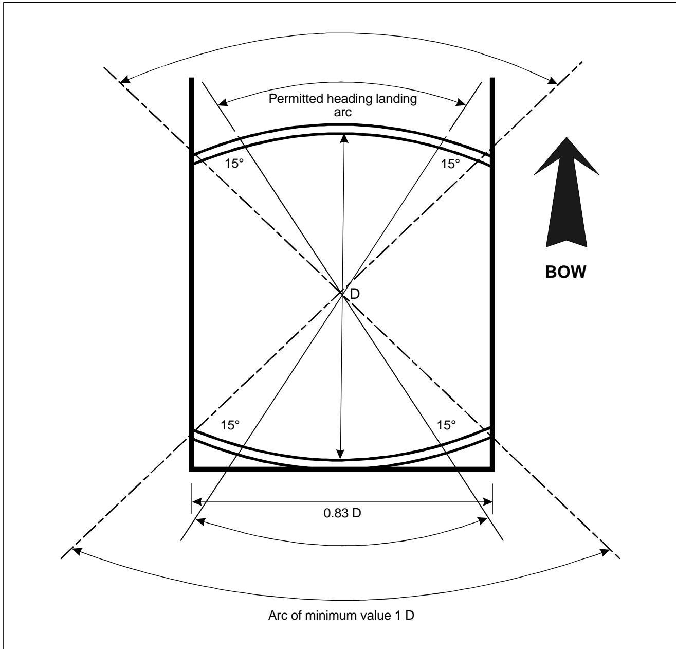
Figure 3-8. Shipboard permitted landing headings for limited heading operations
Note 1 — The ship willneed to be manoeuvred to ensure that the relative wind is appropriate to the direction of the helicopter touchdown heading.
Note 2 — The touchdown heading of the helicopter is limited to the angular distance subtended by the 1 D arc headings, minus the angular distance which corresponds to 15 degrees at each end of the arc.
3.4.8 For non-purpose-built shipboard heliports, the FATO shall be of sufficient size to contain a circle with a diameter not less than 1 D of the largest helicopter the helideck is intended to serve.
3.4.9 No fixed object shall be permited around the edge of the FATO, except for frangible objects, which, because of their function, must be located thereon.
3.4.10 Objects whose function require them to be located on the edge of the FATO shall not exceed a height of 25 cm.
3.4.11 Objects whose function requires them to be located within the FATO (such as ighting or nets) shall not exceed a height of 2.5 cm. Such objects may be present only if they do not represent a hazard to helicopters.
3.4.12 The surface of the FATO shall be skid-resistant to both helicopters and persons.
CHAPTER 4. OBSTACLE RESTRICTION AND REMOVAL
Note.—The objectives of the specifications i this chapter are to define the airspace around heliports to be maintained free from obstacles so as to permit the intended helicopter operations at the heliports to be conducted safely and to prevent the heliports becoming unusable by the growth of obstacles around them. This is achieved by establishing a series of obstacle limitation surfaces that define the limits to which objects may project into the airspace.
4.1 Obstacle limitation surfaces and sectors
Approach surface
4.1.1 Description. An inclined plane or a combination of planes sloping upwards from the end of the safety area and centred on a line passing through the centre of the FATO (see Figure 4-1).
4.1.2 Characteristics. The limits of an approach surface shall comprise:
a) an inner edge horizontal and equal in length to the minimum specified width of the FATO plus the safety area, perpendicular to the centre line of the approach surface and located at the outer edge of the safety area;
b) two side edges originating at the ends of the inner edge and:
-
for other than a precision approach FATO, diverging uniformly at a specified rate from the vertical plane containing the centre line of the FATO;
-
for a precision approach FATO, diverging uniformly at a specified rate from the vertical plane containing the centre line of the FATO, to a specified height above FATO, and then diverging uniformly at a specified rate to a specified final width and continuing thereafter at that width for the remaining length of the approach surface; and
c) an outer edge horizontal and perpendicular to the centre line of the apprach surface and at a specified height above the elevation of the FATO.
4.1.3 The elevation of the inner edge shall be the elevation of the safety area at the point on the inner edge that is intersected by the centre line of the approach surface.
4.1.4 The slope(s) of the approach surface shal be measured in the vertical plane containing the centre line of the surface.
Note.—For heliports used by performance class 2 and 3 helicopters, t is intended that approach paths be selected so as to permit safe forced landing or one-engine-inoperative landings such that, as a minimum requirement, injury to persons on the ground or water or damage to property are minimized. Provisions for forced landing areas are expected to minimize risk of injury to the occupants of the helicopter The most critical helicopter type for which the heliport is intended and the ambient conditions will be factors in determining the suitability of such areas.
Transitional surface
4.1.5 Description. A complex surface along the side of the safety area and part of the side of the approach surface, that slopes upwards and outwards to the inner horizontal surface or a predetermined height (see Figure 4-1).
4.1.6 Characteristics. The limits of a transitional surface shall comprise:
a) a lower edge beginning at the intersection of the side of the approach surface with the inner horizontal surface, or beginning at a specified height above the lwer edge when an inner horizontal surface is not provided, and extending down the side of the approach surface to the inner edge of the approach surface and from there along the length of the side of the safety area parallel to the centre line of the FATO; and
b) an upper edge located in the plane of the iner horizontal urface, or at a specified height above the lower edge when an inner horizontal surface is not provided.
4.1.7 The elevation of a point on the lower edge shall be:
a) along the side of the approach surface — equal to the elevation of the approach surface at that point; and
b) along the safety area — equal to the elevation of the centre line of the FATO opposite that point.
Note.—As a result of b) the transitional urface along the safety area willbe curved if the profile of the FATO is curved, or a plane if the profile is a straight line. The intersection of the transitional surface with the inner horizontal surface, or upper edge when an inner horizontal surface is not provided, wil also be a curved or a straight line depending on the profil of the FATO.
4.1.8 The slope of the transitional surface shall be measured in a vertical plane at right angles to the centre line of the FATO.
Inner horizontal surface
Note.— The intent of the inner horizontal surface is to allow safe visual manoeuvring.
4.1.9 Description. A circular surface located in a horizontal plane above a FATO and its environs (see Figure 4-1).
4.1.10 Characteristics. The radius of the iner horizontal surface shall be measured from the midpoint of the FATO.
4.1.11 The height of the inner horizontal surface shal be measured above an elevation datum established for such purpose.
Note.— Guidance on determining the elevation datum is contained in the Heliport Manual (Doc 9261).
Conical surface
4.1.12 Description. A surface sloping upwards and outwards from the periphery of the inner horizontal surface, or from the outer limit of the transitional surface if an inner horizontal surface is not provided (see Figure 4-1).
4.1.13 Characteristics. The limits of the conical surface shall comprise:
a) a lower edge coincident with the periphery of the inner horizontal surface, or outer limit of the transitional surface if an inner horizontal surface is not provided; and
b) an upper edge located at a specified height above the iner horizontal surface, or above the elevation of the lowest end of the FATO if an inner horizontal surface is not provided.
4.1.14 The slope of the conical surface shall be measured above the horizontal.
Take-off climb surface
4.1.15 Description. An inclined plane, a combination of planes or, when a turn is involved, a complex surface sloping upwards from the end of the safety area and centred on a line passing through the centre of the FATO (see Figure 4-1).
4.1.16 Characteristics. The limits of a take-off climb surface shall comprise:
a) an inner edge horizontal and equal in length to the minimum specified width of the FATO plus the safety area, perpendicular to the centre line of the take-off climb surface and located at the outer edge of the safety area or clearway;
b) two side edges originating at the ends of the inner edge and diverging uniformly at a specified rate from the vertical plane containing the centre line of the FATO; and
c) an outer edge horizontal and perpendicular to the centre line of the take-off climb surface and at a specified height above the elevation of the FATO.
4.1.17 The elevation of the iner edge sha be the elevation of the safety area at the point on the inner edge that is intersected by the centre line of the take-ff climb surface, xcept that when a clearway is provided, the elevation shall be equal to the highest point on the ground on the centre line of the clearway.
4.1.18 In the case of a straight take-off climb surface, the slope shall be measured in the vertical plane containing the centre line of the surface.
4.1.19 In the case of a take-off climb surface involving a turn, the surface shall be a complex surface containing the horizontal norals to its cente line, nd the slope of the cente line shal be the sme as that for strigh take-of climb surface. That portion of the surface between the inner edge and 30 m above the inner edge shall be straight.
4.1.20 Any variation in the direction of the centre line of a take-off climb surface shal be designed so as not to necessitate a turn of radius less than 270 m.
Note.—For heliports used by performance class 2 and 3 helicopters, t is intended that departure paths be selected so as to permit safe forced landings or one-engineinoperative landings such that, as a minimum requirement, njury to persons on the ground or water or damage to property are minimized. Provisions for forced landing areas are expected to minimize risk of injury to the occupants of the helicopter The most critical helicopter type for which the heliport is intended and the ambient conditions will be factors in determining the suitability of such areas.
Obstacle-free sector/surface — helidecks
4.1.21 Description. A complex surface originating at and extending from a reference point on the edge of the FATO of a helideck. In the case of a FATO of less than 1D, the reference point shall be located not les than 0.5 D from the centre of the FATO.
4.1.22 Characteristics. An obstacle-free sector/surface shall subtend an arc of specified angle.
4.1.23 A helideck obstacle-free sector shal comprise two components, one above and one below helideck level (see Figure 4-2):
a) Above helideck level. The surface shall be a horizontal plane level with the elevation of the helideck surface that subtends an arc of at least 210 degrees with the apex located on the periphery of the D reference circle extending outwards to a distance that wil allow for an unobstructed departure path appropriate to the helicopter the helideck is intended to serve.
b) Below helideck level. Within the (minimum) 210-degree arc, the surface shall dditionally extend downward from the edge of the FATO below the elevation of the helideck to water level for an arc of not less than 180 degrees that passes through the centre of the FATO and outwards to a distance that wil allow for safe clearance from the obstacles below the helideck in the event of an engine failure for the type of helicopter the helideck is intended to serve.
Note.—For both the above obstacle-fre sectors for helicopters operated in performance class1 or 2, the horizontal extent of these distances from the helideck wil be compatible with the one-engine-inoperative capability of the helicopter ype to be used.
Limited obstacle surface — helidecks
Note.— Where obstacles are necessarily located on the structure, a helideck may have a limited obstacle sector.
4.1.24 Description. A complex surface originating at the reference point for the obstacle-free sector and extending over the arc not covered by the obstacle-free sector within which the height of obstacles above the level of the FATO will be prescribed.
4.1.25 Characteristics. A limited obstacle sector shall not subtend an arc greater than 150 degrees. Its dimensions and location shall be as indicated in Figure 4-3.
4.2 Obstacle limitation requirements
Note.— The requirements for obstacle limitation surfaces are specified on the basis of the intended use of a FATO, ie. approach manoeuvre to hover or landing, or take-of manoeuvre and type of approach, and are intended to be applied when such use is made of the FATO.In cases where operations are conducted to or from both directions of a FATO, then the function of certain surfaces may be nullified because of more stringent requirements of another lower surface.
Surface-level heliports
4.2.1 The following obstacle limitation surfaces shall be established for a precision approach FATO:
a) take-off climb surface;
b) approach surface;
c) transitional surfaces; and
d) conical surface.
4.2.2 The following obstacle limitation surfaces shall be established for a non-precision approach FATO:
a) take-off climb surface;
b) approach surface;
c) transitional surfaces; and
d) conical surface if an inner horizontal surface is not provided.
4.2.3 The following obstacle limitation surfaces shal be established for a non-instrument FATO:
a) take-off climb surface; and
b) approach surface.
4.2.4 Recommendation.— The following obstacle limitation surfaces should be established for a non-precision approach FATO:
a) inner horizontal surface; and
b) conical surface.
Note.—An inner horizontal surface may not be required if a straight-in non-precision approach is provided at both ends.
4.2.5 The slopes of the surfaces shal not be greater than, and their other dimensions not less than those specified in Tables 4-1 to 4-4 and shall be located as shown in Figures 4-4 to 4-8.
4.2.6 New objects or extensions of existing objects shall not be permitted above any of the surfaces in 4.2.1 to 4.2.4 except when, in the opinion of the appropriate authority, the new object or extension would be shielded by an existing immovable object.
Note.— Circumstances in which the shielding principle may reasonably be applied are described in the Airport Services Manual, Part 6 (Doc 9137).
4.2.7 Recommendation.— Existing objects above any of the surfaces in 4.2.1 to 4.2.4 should, as far as practicable, be removed except when, in the opinion of the appropriate authority, the object is shielded by an existing immovable object, or after aeronautical study it is determined that the object would not adversely affect the safety or significantly affect the regularity of operations of helicopters.
Note.— The application of curved take-off climb surfaces as specfied in 4.1.19 may alleviate the problems created by objects infringing these surfaces.
4.2.8 A surface-level heliport shall have at least two take-of climb and approach surfaces, separated by not less than 150 degrees.
4.2.9 Recommendation.— The number and orientation of take-of climb and approach surfaces should be such that the usability factor of a heliport is not less than 95 per cent for the helicopters the heliport is intended to serve.
Elevated heliports
4.2.10 The obstacle limitation requirements for elevated heliports shall conform to the requirements for surface-level heliports specified in 4.2.1 to 4.2.7.
4.2.11 An elevated heliport shall have at least two take-off limb and approach surfaces separated by not less than 150 degrees.
Helidecks
Note.— The following specifications are for helidecks located on a structure and engaged in such actities as mineral exploitation, research, or construction, but excluding heliports on ships.
4.2.12 A helideck shall have an obstacle-free sector.
Note.— A helideck may have a limited obstacle sector (see 4.1.25).
4.2.13 There shal be no fixed obstacles within the obstacle-free sector above the obstacle-free surface.
4.2.14 In the immediate vicinity of the helideck, obstacle protection for helicopters shall be provided below the heliport level. This protection shall extend over an arc of at least 180 degrees with the origin at the centre of the FATO, with a descending gradient having a ratio of one unit horizontally to five units vertically from the edges of the FATO within the 180-degree sector. This descending gradient may be reduced t a ratio of one unit horizontaly to three within the 180-dgree sector for multi-engine helicopters operated in performance class 1 or 2 (see Figure 4-2).
4.2.15 Where a mobile obstacle or combination of obstacles within the obstacle-free sector is essential for the operation of the installation, the obstacle(s) shall not subtend an arc exceeding 30 degrees, s measured from the centre of the FATO.
4.2.16 Within the 150-degre limited obstacle surface/sector out to a distance of 0.62 D, measured from the centre of the FATO, objects shall not exceed a height of 0.05 D above the FATO. Beyond tat arc, out to an overal distance of 0.83 D the limited obstacle surface rises at a rate of one unit vertically for each two units horizontally (see Figure 4-3).
Shipboard heliports
Purpose-built heliports located forward or aft
4.2.17 The specifications in 4.2.20 and 4.2.22 shal be applicable for shipboard heliports completed on or after 1 January 2012.
4.2.18 When helicopter operating areas are provided in the bow or stern of a ship, they shall aply the obstacle criteria given in 4.2.12, 4.2.14 and 4.2.16.
Amidships location
4.2.19 Forward and aft of the FATO shall be two symmetrically located sectors, each covering an arc of 150 degrees, with their apexes on the periphery of the FATO D reference circle. Within the area enclosed by these two sectors, there shall be no objects ising above the level of the FATO, xcept those ids essential for the safe operation of a helicopter and then only up to a maximum height of 25 cm.
4.2.20 Objects whose function requires them to be located within the FATO (such as lighting or nets) shallnot exceed a height of 2.5 cm. Such objects may be present only if they do not represent a hazard to helicopters.
Note.— Examples of potential hazards include nets or raised fitings on the deck that might induce dynamic rollover for helicopters equipped with skids.
4.2.21 To provide further protection from obstacles fore and aft of the FATO, rising surfaces with gradients of one unit vertically to five units horizontally shall extend from the entire length of the edges of the two 150-degree sectors. These surfaces shal extend for a horizontal distance equal to at last 1 D of the largest helicopter te FATO is intended t sere and shall not be penetrated by any obstacle (see Figure 4-9).
Non-purpose-built heliports
Ship's side location
4.2.22 No objects shal be located within the FATO, except those aids essential for the safe operation of a helicopter (such as nets or lighting) and then only up to a maximum height of 2.5 cm. Such objects shall be present only if they do not represent a hazard to helicopters.
4.2.23 From the fore and aft midpoints of the D reference circle, an area shall extend to the ship's rail to a fore and aft distance of 1.5 times the diameter of the FATO, lcated symmetrically about the athwartships bisector of the reference circle. Within this sector there shall be no objects rising above the level of the FATO, except those aids essential to the safe operation of the helicopter and then only up to a maximum height of 25 cm (see Figure 4-10).
4.2.24 A horizontal surface sha be provided, at least 0.25 times the diameter of the D reference circle, which shall surround the FATO and the obstacle-freesector, at a height of 0.05 times the diameter of the reference circle, which no object shall penetrate.
Winching areas
4.2.25 An area designated for winching on-board ships shall comprise a circular clear zone of diameter 5 m and extending from the perimeter of the clear zone, a concentric manoeuvring zone of diameter 2 D (see Figure 4-11).
4.2.26 The manoeuvring zone shall comprise 2 areas:
a) the inner manoeuvring zone extending from the perimeter of the clear zone and of a circle of diameter not less than 1.5 D; and
b) the outer manoeuvring zone extending from the perimeter of the inner manoeuvring zone and of a circle of diameter not less than 2 D.
4.2.27 Within the clear zone of a designated winching area, no objects shall be located above the level of ts surface.
4.2.28 Objects located within the iner manoeuvring zone of a designated winching area shal not exceed a height of 3 m.
4.2.29 Objects located within the outer manoeuvring zone of a designated winching area shal not exceed a height of 6 m.
Figure 4-1. Obstacle limitation surfaces
Figure 4-2. Helideck obstacle-free sector
Figure 4-3. Helideck obstacle limitation sectors
Figure 4-4. Take-off climb/approach surface (non-instrument FATO)
Figure 4-5. Take-off climb surface for instrument FATO
Figure 4-6. Approach surface for precision approach FATO
Figure 4-7. Approach surface for non-precision approach FATO
Figure 4-8. Transitional, inner horizontal and conical obstacle limitation surfaces
Figure 4-9. Midship non-purpose-built heliport obstacle imitation surfaces
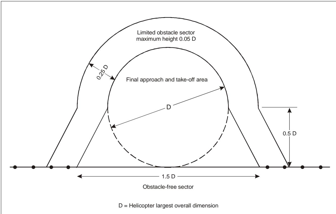
Figure 4-10. Ship's side non-purpose-built heliport obstacle limitation surfaces
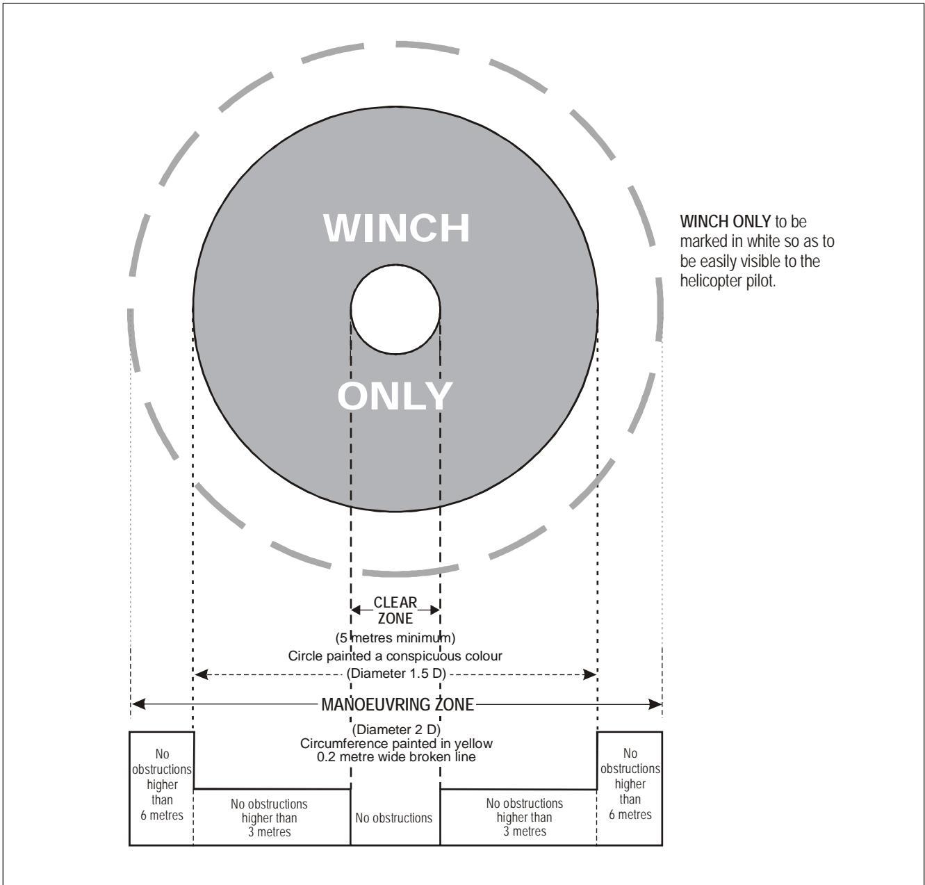
Figure 4-11. Winching area of a ship
Table 4-1. Dimensions and slopes of obstacle limitation surfaces
NON-INSTRUMENT AND NON-PRECISION FATO
| Non-instrument (visual) FATO | Non-precision (instrument approach) | ||||
| Helicopter performance class | |||||
| Surface and dimensions | 2 | 3 | FATO | ||
| APPROACH SURFACE | Width of safety area | Width of safety area | |||
| Width of inner edge Location of inner edge | Boundary | Boundary | |||
| First section | 10% | 10% | 10% | 16% | |
| Divergence | day | 15% | 15% | 15% | |
| night | $2 4 5 \mathrm { m } ^ { \mathrm { a } }$ | $2 4 5 \mathrm { m ^ { a } }$ | $2 4 5 \mathrm { m ^ { a } }$ | 2500m | |
| Length | day | $2 4 5 \mathrm { m ^ { a } }$ | $2 4 5 \mathrm { m ^ { a } }$ | $2 4 5 \mathrm { m ^ { a } }$ | |
| night | $4 9 \mathrm m ^ { \mathrm b }$ | $4 9 \mathrm m ^ { \mathrm b }$ | $4 9 \mathrm m ^ { \mathrm b }$ | 890m | |
| Outer width | day | $7 3 . 5 \mathrm { m } ^ { \mathrm { b } }$ | $7 3 . 5 \mathrm { m } ^ { \mathrm { b } }$ | $7 3 . 5 \mathrm { m } ^ { \mathrm { b } }$ | |
| Slope (maximum) | night | $8 \% ^ { \mathrm { a } }$ | $8 \% ^ { \mathrm { a } }$ | $8 \% ^ { \mathrm { a } }$ | 3.33% |
| Second section | |||||
| Divergence | day | 10% | 10% 15% | 10% 15% | |
| Length | night | 15% | c | ||
| day | c c | c c | c | ||
| Outer width | night | d | d | d | |
| day | d | d | d | ||
| Slope (maximum) | night | 12.5% | 12.5% | 12.5% | |
| Third section | |||||
| Divergence Length | parallel | parallel | parallel | ||
| day | e | e e | e e | ||
| Outer width | night | e d | d | d | |
| day | d | d | d | ||
| night | 15% | 15% | 15% | ||
| Slope (maximum) | |||||
| INNER HORIZONTAL Height | 45m | ||||
| Radius | 2000m | ||||
| CONICAL | |||||
| Slope | 5% 55m | ||||
| Height | |||||
| TRANSITIONAL | |||||
| Slope | 20% | ||||
| Height | 45m | ||||
a. Slope and length enables helicopters to decelerate for landing while observing "avoid" areas.
b. The width of the inner edge shall be added to this dimension.
. diameters for night operations.
d. Seven rotor diameters overall width for day operations or 10 rotor diameters overall width for night operations.
e.Deterneb the istance fr ner ee towhere te apprch urfce reaches heig of 150 abve e elation f te ier .
Table 4-2. Dimensions and slopes of obstacle imitation surfaces
INSTRUMENT (PRECISION APPROACH) FATO
| 3° approach | 6°approach | |||||||
| Height above FATO | Height above FATO | |||||||
| Surface and dimensions | 90m (300 ft) | 60m (200 ft) | 45m (150 ft) | 30m (100 ft) | 90m (300 ft) | 60m (200 ft) | 45m (150 ft) | 30m (100 ft) |
| APPROACH SURFACE | ||||||||
| Length of inner edge | 90m | 90m | 90m | 90m | 90m | 90m | 90m | 90m |
| Distance from end of FATO | 60m | 60m | 60m | 60m | 60m | 60m | 60m | 60m |
| Divergence each side to height above FATO | 25% | 25% | 25% | 25% | 25% | 25% | 25% | 25% |
| Distance to height above FATO | 1745m | 1163m | 872m | 581m | 870m | 580m | 435m | 290m |
| Width at height above FATO | 962m | 671m | 526m | 380m | 521m | 380m | 307.5m | 235m |
| Divergence to parallel section | 15% | 15% | 15% | 15% | 15% | 15% | 15% | 15% |
| Distance to parallel section | 2793m | 3763m | 4246m | 4733m | 4250m | 4733m | 4975m | 5217m |
| Width of parallel section | 1800m | 1800m | 1800m | 1800m | 1800m | 1800m | 1800m | 1800m |
| Distance to outer edge | 5462m | 5074m | 4882m | 4686m | 3380m | 3187m | 3090m | 2993m |
| Width at outer edge | 1800m | 1800m | 1800m | 1800m | 1800m | 1800m | 1800m | 1800m |
| Slope of first section | 2.5% | 2.5% | 2.5% | 2.5% | 5% | 5% | 5% | 5% |
| Length of first section | (1:40) 3000m | (1:40) 3000m | (1:40) 3000m | (1:40) 3000m | (1:20) 1500m | (1:20) 1500m | (1:20) 1500m | (1:20) 1500m |
| Slope of second section | 3% | 3% | 3% | 3% | 6% | 6% | 6% | 6% |
| Length of second section | (1:33.3) 2500m | (1:33.3) 2500m | (1:33.3) 2500m | (1:33.3) 2500m | (1:16.66) 1250m | (1:16.66) 1250m | (1:16.66) 1250m | (1:16.66) 1250m |
| Total length of surface | 10 000m | 10 000m | 10 000 m | 10000m | 8500m | 8500m | 8500m | |
| 8500m | ||||||||
| CONICAL Slope | 5% | 5% | 5% | 5% | 5% | 5% | 5% | 5% |
| Height | 55m | 55m | 55m | 55m | 55m | 55m | 55m | 55m |
| TRANSITIONAL | ||||||||
| Slope | 14.3% | 14.3% | 14.3% | 14.3% | 14.3% | 14.3% | 14.3% | 14.3% |
| Height | 45m | 45m | 45m | 45m | 45m | 45m | 45m | 45m |
Table 4-3. Dimensions and slopes of obstacle limitation surfaces
STRAIGHT TAKE-OFF
| Non-instrument (visual) | |||||
| Helicopter performance class | |||||
| Surface and dimensions | 2 | 3 | Instrument | ||
| TAKE-OFF CLIMB Width of inner edge | Width of safety area | 90m | |||
| Location of inner edge | Boundary or end of clearway | Boundary or end of clearway | |||
| First section | |||||
| Divergence | day | 10% | 10% | 10% | 30% |
| night | 15% | 15% | 15% | ||
| Length | day | a | $2 4 5 ~ \mathrm { m } ^ { \mathrm { b } }$ | $2 4 5 \mathrm { m } ^ { \mathrm { b } }$ | 2850m |
| night | a | $2 4 5 ~ \mathrm { m } ^ { \mathrm { b } }$ | $2 4 5 \mathrm { m } ^ { \mathrm { b } }$ | ||
| Outer width | day | C | $4 9 \mathrm { m ^ { d } }$ | $4 9 \mathrm { m ^ { d } }$ | 1800m |
| night | c | $7 3 . 5 \mathrm { m } ^ { \mathrm { d } }$ | $7 3 . 5 \mathrm { m } ^ { \mathrm { d } }$ | ||
| Slope (maximum) | 4.5%* | $8 \% ^ { \mathrm { b } }$ | $8 \% ^ { \mathrm { b } }$ | 3.5% | |
| Second section | |||||
| Divergence | day | parallel | 10% | 10% | parallel |
| night | parallel | 15% | 15% | ||
| Length | day | e | a | a | 1510m |
| night | e | a | a | ||
| Outer width | day | C | c | c | 1800m |
| night | C | C | C | ||
| Slope (maximum) | 4.5%* | 15% | 15% | 3.5%* | |
| Third section | parallel | ||||
| Divergence Length | day | parallel e | e | parallel 7640m | |
| e | e | ||||
| Outer width | night | c | C | 1800m | |
| day | c | c | |||
| Slope (maximum) | night | 15% | 15% | 2% | |
diameters for night operations.
b. Slope and length provides helicopters with an area to accelerate and climb while observing "avoid'" areas.
c. Seven rotor diameters overall width for day operations or 10 rotor diameters overall width for night operations.
d. The width of the inner edge shall be added to this dimension.
e.Determined by th distance from the inner ege to where the surface reaches a height of 150 m above the elevation f th iner edge.
*This slope exceeds the maximum mass one-engine-inoperative cimb gradient of many helicopters which are curently operating.
Table 4-4. Criteria for curved take-off climb/approach area
NON-INSTRUMENT FINAL APPROACH AND TAKE-OFF
| Facility Requirement | |
| Directional change | |
| Radius of turn on centre line | |
| Distance to inner gate* (a) For performance class 1 helicopters — not less than 305 m from the end of the safety area or helicopter clearway. | |
| (b) For performance class 2 and 3 helicopters — not less than 370 m from the end of the FATO. | |
| Width of inner gate —day Width of the inner edge plus 20% of distance to inner gate. | |
| night | |
| Width of the inner edge plus 30% of distance to inner gate. Width of outer gate e — day Width of inner edge plus 20% of distance to inner gate out to minimum | |
| width of 7 rotor diameters. — night Width of inner edge plus 30% of distance to inner gate out to a | |
| minimum width of 10 rotor diameters. Elevation of inner and outer gates | |
| Determined by the distance from the inner edge and the designated gradient(s). | |
| As given in Tables 4-1 and 4-3. | |
| As given in Tables 4-1 and 4-3. | |
| Slopes Divergence | |
| Total length of area As given in Tables 4-1 and 4-3. | |
| * This is the minimu | |
* This is the minimum distance required prior to initiating a turn after take-of or completing a turn in the final phase.
Note.— More than one turn may be necessary in the total length of the take-off climb/approach area. The same criteria wil apply for each subsequent turn, except that the widths of the inner and outer gates will normally be the maximum width of the area.
CHAPTER 5. VISUAL AIDS
5.1 Indicators
5.1.1 Wind direction indicators
Application
5.1.1.1 A heliport shall be equipped with at least one wind direction indicator.
Location
5.1.1.2 A wind direction indicator shallbe located so as to indicate the wind conditions over the FATO and in such a way as to be fre from the effects of airflow disturbances caused by nearby objects or rotor downwash. It shall be visible from a helicopter in flight, in a hover or on the movement area.
5.1.1.3 Recommendation.— Where a TLOF may be subject to a disturbed airflow, then additional wind direction indicators located close to the area should be provided to indicate the surface wind on the area.
Note.— Guidance on the location of wind direction indicators is given in the Heliport Manual (Doc 9261).
Characteristics
5.1.1.4 A wind direction indicator sha be constructed so that t gives a clear indication of the direction of the wind and a general indication of the wind speed.
5.1.1.5 Recommendation.— An indicator should be a truncated cone made of lightweight fabric and should have the following minimum dimensions:
| Surface-level heliports | Elevated heliports and helidecks | |
| Length | 2.4m | 1.2 m |
| Diameter (larger end) | 0.6 m | 0.3m |
| Diameter (smaller end) | 0.3 m | 0.15 m |
5.1.1.6 Recommendation.— The colour of the wind direction indicator should be so selected as to make it clearly visible and understandable from a height of at least 200 m (650 ft) above the heliport, having regard to background. Where practicable, a single colour, preferably white or orange, should be used. Where a combination of two colours is required to give adequate conspicuity against changing backgrounds, they shoul preferably be orange and white, red and white, or black and white, and should be arranged in five alternate bands the first and last band being the darker colour.
5.1.1.7 A wind direction indicator at a heliport intended for use at night shall be illuminated.
5.2 Markings and markers
Note.— See Annex 14, Volume I, 5.2.1.4, Note 1, concerning improving conspicuity of markings.
5.2.1 Winching area marking
Application
5.2.1.1 Winching area markings shall be provided at a designated winching area (see Figure 4-11).
Location
5.2.1.2 Winching area markings shall be located so that their centre(s) coincides with the centre of the clear zone of the winching area.
Characteristics
5.2.1.3 Winching area markings shall comprise a winching area clear zone marking and a winching area manoeuvring zone marking.
5.2.1.4 A winching area clear zone marking shall consist of a solid circle of not less than 5 m in diameter and of a conspicuous colour.
5.2.1.5 A winching circle manoeuvring zone shall consist of a broken circle of ine of 0.2 m in width and of a diameter not less han 2 D and be marked in a conspicuus colour. Within it WINCH ONLY' shall be marked to be easily visible t the pilt.
5.2.2 Heliport identification marking
Application
5.2.2.1 A heliport identification marking shall be provided at a heliport.
Location
5.2.2.2 A heliport identification marking shall be located within the FATO, at or near the centre of the area or, when used in conjunction with runway designation markings, at each end of the area.
Characteristics
5.2.2.3 A heliport identification marking, except for a heliport at a hospital, shal onsist of a letter H, white in colour. The dimensions of the marking shal e no les than those shown in Figure 5-1 and where the marking is used in conjunction with the FATO designation marking specified in 5.2.5, its dimensions shall be increased by a factor of 3.
5.2.2.4 A heliport identification marking for a heliport at a hospital shall consist of a letter H, red in colour, on a white cross made of squares adjacent to each of the sides of a square containing the H as shown in Figure 5-1.
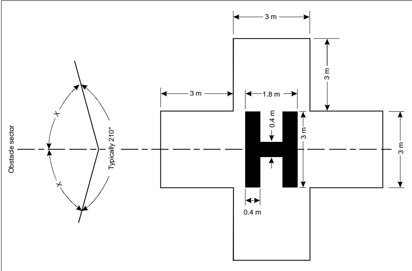
Figure 5-1. Heliport identification marking
(shown with hospital cross and orientation with obstacle-free sector)
5.2.2.5 A heliport identification marking shall be oriented with the crossarm of the H at right angles to the preferred final approach direction. For a helideck the cross arm shal e on or parallel to the bisector of the obstacle-free sector as shown in Figure 5-1.
5.2.2.6 Recommendation.— On a helideck, the size of the heliport identification “H" marking should have a height of 4 m with an overall width not exceeding 3 m and a stroke width not exceeding 0.75 m.
5.2.3 Maximum allowable mass marking
Application
5.2.3.1 Recommendation.—A maximum allowable mass marking should be displayed at an elevated heliport and at a helideck.
Location
5.2.3.2 Recommendation.—A maximum allowable mass marking should be located within the TLOF and so arranged as to be readable from the preferred final approach direction.
Characteristics
5.2.3.3 A maximum allowable mass marking shallconsist of a one-, two- or three-digit number. The marking shall be expressed in tonnes (1 00 kg) rounded to the nearest 1000 kg followed by a lettr '". Where States use mass in pounds, the maximum allowable mass marking shall indicate the allowable helicopter mass in thousands of pounds rounded to the nearest 1 000 1b.
Note.— Where States express the maximum allowable mass in pounds, it is not appropriate to suffix with the letter t”" which is used only to indicate metric tonnes. Guidance on markings where States use imperial units is given in the Heliport Manual (Doc 9261).
5.2.3.4 Recommendation.— The allwable mass marking should be expressed to the nearest 100 kg. The marking should be presented to one decimal place and rounded to the nearest 100 kg followed by the letter "t". Where States use mass in pounds, the maximum allowable mass marking should indicate the allowable helicopter mass in hundreds of ounds rounded to the nearest 100 Ib.
5.2.3.5 Recommendation.— The numbers and the letter of the marking should have a colour contrasting with the background and should be in the form and proportion shown in Figure 5-2, except that where space is imited, such as on an off shore helideck or shipboard heliport, t may be necessary to reduce the size of the marking to characters with an overall height of not less than 90 cm with a corresponding reduction in the width and thickness of the figures.
5.2.4 Maximum allowable D-value marking
Application
5.2.4.1 Recommendation.— The D-value marking should be displayed at an elevated heliport and at a helideck.
Location
5.2.4.2 Recommendation.— A maximum allowable D-value marking should be located within the FATO and so arranged as to be readable from the preferred final approach direction.
Characteristics
5.2.4.3 The D-value shall be marked on the FATO in a contrasting colour to it, preferably white. The D-value shall be rounded to the nearest whole number with 0.5 rounded down, e.g. 19.5 becomes 19 and 19.6 becomes 20.
5.2.5 Final approach and take-off area marking or marker
Application
5.2.5.1 FATO marking or markers shal be provided at a surface-level heliport on ground where the extent of the FATO is not self-evident.
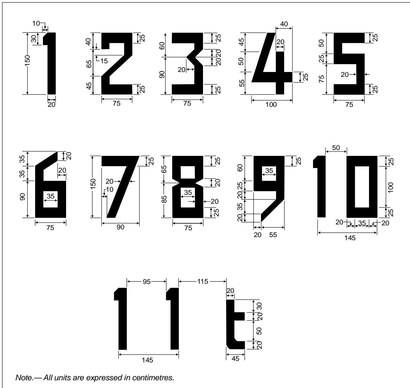
Figure 5-2. Form and proportions of numbers and letter for maximum allowable mass marking
Location
5.2.5.2 FATO marking or markers shall be located on the boundary of the FATO.
Characteristics
5.2.5.3 FATO marking or markers shall be spaced:
a) for a square or rectangular area, at equal intervals of not more than 50 m with at last three markings or markers on each side including a marking or marker at each corner; and
b) for any other shaped area, including a circular area, at equal intervals of not more than 10 m with a minimum number of five markings or markers.
5.2.5.4 A FATO marking shal be a rectangular stripe with a length of 9 m or one-fifth of the side of the FATO which it defines and a width of 1 m. Where a marker is used its characteristis shall conform to those specified in Annex 14, Volume I, 5.5.8.3, except that the height of the marker shall not exceed 25 cm above ground or snow level.
5.2.5.5 A FATO marking shal be white.
5.2.6 Final approach and take-off area designation marking
Application
5.2.6.1 Recommendation.—A FATO designation marking should be provided where it is necessary to designate the FATO to the pilot.
Location
5.2.6.2 A FATO designation marking shall be located at the beginning of the FATO as shown in Figure 5-3.
Characteristics
5.2.6.3 A FATO designation marking shall consist of a runway designation marking described in Annex 14, Volume I, 5.2.2.4 and 5.2.2.5, supplemented by an H, specified in 5.2.2 above, and as shown in Figure 5-3.
5.2.7 Aiming point marking
Application
5.2.7.1 Recommendation.—An aiming point marking should be provided at a heliport where it is necessary for a pilot to make an approach to a particular point before proceeding to the TLOF.
Location
5.2.7.2 The aiming point marking shall be located within the FATO.
Characteristics
5.2.7.3 The aiming point marking shall be an equilateral triangle with the bisector of one of the angles aligned with the preferred approach direction. The marking shall consist of continuous white lines, and the dimensions of the marking shall conform to those shown in Figure 5-4.
Figure 5-3. FATO designation marking
Figure 5-4. Aiming point marking
5.2.8 Touchdown and lift-off area marking
Application
5.2.8.1 TLOF marking shall be provided on a heliport if the perimeter of the TLOF is not self-evident.
Location
5.2.8.2 The TLOF marking shall be located along the perimeter of the TLOF.
Characteristics
5.2.8.3 A TLOF marking shall consist of a continuous white line with a width of at least 30 cm.
5.2.9 Touchdown/positioning marking
Application
5.2.9.1 A touchdown/positioning marking shall be provided where it is necesary for a helicopter to touch down or be accurately placed in a specific position.
Location
5.2.9.2 A touchdown/positioning marking shall be located so that when the pilot's seat is over the marking, the undercarriage wil be inside the load-bearing area, and al parts of the helicopter wil e clear of any obstacle by a safe margin.
5.2.9.3 On a helideck the centre of the touchdown marking shall be located at the centre of the FATO, except that the marking may be fset away from the origin of the obstacle-free sector by no more than 0.1 D where an aeronautical study indicates such offsetting to be necessary and that a marking so offset would not adversely affect the safety.
Note.—It is not considered appropriate to offset a touchdown marking on a heliport located on the bow of a vessel, or for any helideck where the D-value is 16 m or less.
Characteristics
5.2.9.4 A touchdown/positioning marking shal be a yellow circle and have a line width of at east 0.5 m. For a helideck, the line width shall be at least 1 m.
5.2.9.5 The inner diameter of the circle shall be 0.5 D of the largest helicopter the TLOF is intended to serve.
5.2.9.6 When a net is located on the surface of a FATO, it shall be large enough to cover the whole of the touchdown/positioning marking and shall not obscure other essential markings.
5.2.10 Heliport name marking
Application
5.2.10.1 Recommendation.—A heliport name marking should be provided at a heliport where there is insufficient alternative means of visual identification.
Location
5.2.10.2 Recommendation.— The heliport name marking should be placed on the heliport so as to be visible, as far as practicable, at all angles above the horizontal. Where an obstacle sector exists the marking should be located on the obstacle side of the H identification marking.
Characteristics
5.2.10.3 A heliport name marking shall consist of the name or the alphanumeric designator of the heliport as used in radiotelephony communications.
5.2.10.4 Recommendation.— The characters of the marking should be not less than 3 m in height at surface-level heliports and not less than 1.2 m on elevated heliports and helidecks. The colour of the marking should contrast with the background.
5.2.10.5 A heliport name marking intended for use at night or during conditions of poor visibility shal be iluminated, either internally or externally.
5.2.11 Helideck obstacle-free sector marking
Application
5.2.11.1 Recommendation.—A helideck obstacle-free sector marking should be provided at a helideck.
Location
5.2.11.2 A helideck obstacle-fre sector marking shal be located on the FATO perimeter or on the TLOF marking.
Characteristics
5.2.11.3 The helideck obstacle-freesector marking shall indicate the origin of the obstacle-free sector and the directions of the limits of the sector.
Note.— Example figures are given in the Heliport Manual (Doc 9261).
5.2.11.4 The height of the chevron shall equal the width of the TLOF marking but shall be not less than 30 cm.
5.2.11.5 The chevron shall be marked in a conspicuous colour.
5.2.12 Helideck surface marking
Characteristics
5.2.12.1 Recommendation.— The helideck surface bounded by the FATO should be of a dark colour using a high friction coating. Where the surface coating may have a degrading effect on friction qualitis it may be necessary to leave the helideck surface untreated. In such cases, the conspicuity of the markings should be enhanced by outlining the deck markings with a contrasting colour.
5.2.13 Helideck prohibited landing sector marking
Application
5.2.13.1 Recommendation.— Helideck prohibited landing sector marking should be provided where it is necessary to prevent the helicopter from landing within specified headings.
Location
5.2.13.2 Recommendation.— The prohibited landing sector markings should be located on the touchdown/positioning marking to the edge of the FATO, within the relevant headings as shown in Figure 5-5.
Characteristics
5.2.13.3 The prohibited landing sector markings shall be indicated by white and red hatched markings as shown in Figure 5-5.
5.2.14 Marking for taxiways
Note.—The specifications for taxiway centre line marking and taxi-holding position markings in Annex 14, Volume I, 5.2.8 and 5.2.9, are equally applicable to taxiways intended for ground taxing of helicopters.
5.2.15 Air taxiway markers
Application
5.2.15.1 Recommendation.— An air taxiway should be marked with air taxiway markers.
Note.— These markers are not meant to be used on helicopter ground taxiways.
Location
5.2.15.2 Air taxiway markers shall be located along the centre line of the air taxiway and shall be spaced at intervals of not more than 30 m on straight sections and 15 m on curves.
Characteristics
5.2.15.3 An air taxiway marker shall be frangible and when installed shl not exceed 35 cm above ground or snow level. The surface of the marker as viewed by the pilot shal e a rectangle with a height to width ratio of approximately 3 to 1 and shall have a minimum area of 150 cm2 as shown in Figure 5-6.
5.2.15.4 An air taxiway marker sha be divided into three equal, horizontal bands coloured yellow, green and yellow, respectively.If the air taxiway is to be used at night, the markers shall be internally illuminated or retroreflective.
5.2.16 Air transit route markers
Application
5.2.16.1 Recommendation. When established an air transit route should be marked with air transit route markers.
Location
5.2.16.2 Air transit route markers sha be located along the centre line of the air transit route and shall be spaced at intervals of not more than 60 m on straight sections and 15 m on curves.

Figure 5-5. Helideck prohibited landing sector marking
Figure 5-6. Air taxiway marker
Characteristics
5.2.16.3 An air transit route marker shall be frangible and when installed shall not exceed 1 m above ground or snow level. The surface of the marker as viewed by the pilot shal be a rectangle with a height to width ratio of approximately 1 to 3 and shall have a minimum area of 1 500 cm2 as shown in the examples in Figure 5-7.
5.2.16.4 An air transit route marker shall be divided into three equal, vertical bands coloured yellow, green and yellow, respectively. If the air transit route is to be used by night, the marker shall be internll illuminated or retroreflective.
5.3 Lights
5.3.1 General
Note 1.— See Annex 14, Volume I1, 5.3.1, concerning specifications on screening of non-aeronautical ground lights, and design of elevated and inset lights.
Note 2.—In the case of helidecks and heliports lcated near navigable waters, consideration needs to be given to ensuring that aeronautical ground lights do not cause confusion to mariners.
Note 3.—As helicopters will generally come very close to extraneous light sources,it is particularly important to ensure that, unless such lights are navigation ights exhibited in accordance with international regulations, they are screened or located so as to avoid direct and reflected glare.
Note 4.— The following specifications have been developed for systems intended for use in conjunction with a non-instrument or non-precision FATO.
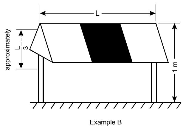
Figure 5-7. Air transit route marker
5.3.2 Heliport beacon
Application
5.3.2.1 Recommendation.—A heliport beacon should be provided at a heliport where:
a) long-range visual guidance is considered necessary and is not provided by other visual means; or
b) identification of the heliport is difficult due to surrounding lights.
Location
5.3.2.2 The heliport beacon shal be located on or adjacent to the heliport preferably at an elevated position and s that it does not dazzle a pilot at short range.
Note.—Where a heliport beacon is likely to dazzle pilots at short range,it may be switched of during th final stages of the approach and landing.
Characteristics
5.3.2.3 The heliport beacon shal emit repeated series of equispaced short duration white flashes in the format in Figure 5-8.
5.3.2.4 The light from the beacon shall show at all angles of azimuth.
5.3.2.5 Recommendation. The effective light intensity distribution of each flash should be as shown in Figure 5-9, illustration 1.
Note.— Where brilliancy control is desired, settings of 10 per cent and 3 per cent have been found to be satisfactory. In addition, shielding may be necessary t ensure that pilots are not dazzled during the final stages of the approach and landing.
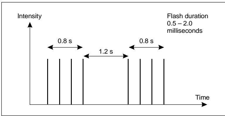
Figure 5-8. Heliport beacon flash characteristics
| san nl | saued uaosauun | o eo | pue ye — | s | p0000 6 | a | |||
| (bl1 uao) | 008L+ | ynwzy | 。08L- | ||||||
| 08L+ | ynwzy | PO1 P300L | 。0 。ε | 8 | |||||
| p30ε | 。08L- 9535。 | 00L 08 | |||||||
| (l uaab) | ynwzV 008L- | po gl | 。0>3>。g 。3>。01 | 。0L | 。S | 09 0 7 | |||
| 08l+ 2po g | 。0 | p8 | 0>3> 1 | po 00L p09 | 。02 | 。6 。9 | |||
| po | 。0l | pε | 。06>3> 。07 | pOL | 。92 。08 | ynu.zy | ▲ | ||
| 。02 | () | M 08 | |||||||
| 2p08 p | 。0ε | 9 p30006 | |||||||
| 2/po09 | 。0t | buung peans | |||||||
| gg | |||||||||
| 。09 | (4l al) | (al a) | |||||||
| 。08L+ 002 | ynuizy 。08L- | 。08l+ | ynwzy 。08L- | (al a) 。08L+ | yunwzy 。08L- | ||||
| 2po gg | 。06 | p00 | 。0 | 。0 | P000L1 | 。0 | |||
| 。2 | 00 | 。0 | p0009 | 02 | |||||
| 009 | 。g | 。9 | 0009 P200L | 022 | |||||
| xp2009ε | 。9 | 。9 | 。 | ||||||
| xP009 | |||||||||
| p0009 | 。6 | 00 | 。6 | 。L | |||||
| 009 | 00 | 。0L | |||||||
| 。S1 | 。L | ||||||||
| ea | |||||||||
Figure 5-9. Isocandela diagrams of lights meant for helicopter non-instrument and non-precision approaches
5.3.3 Approach lighting system
Application
5.3.3.1 Recommendation.— An approach lighting system should be provided at a heliport where it is desirable and practicable to indicate a preferred approach direction.
Location
5.3.3.2 The approach lighting system shall be located in a straight line along the preferred direction of approach.
Characteristics
5.3.3.3 Recommendation.—An approach lighting system should consist of a row of three lights spaced uniformly at 30 m intervals and of a crossbar 18 m in length at a distance of 90 m from the perimeter of the FATO as shown in Figure 5-10. The lights forming the crossbar should be as nearly as practicable in a horizontal straight line at right angles to, and bisected by, the line of the centre lin lights and spaced at 4.5 m intervals.Where there is the need to make the final aproach course more conspicuous additional lights spaced uniformly at 30 m intervals should be added beyond the crossbar. The ights beyond the crossbar may be steady or sequenced flashing, depending upon the environment.
Note.— Sequenced flashing lights may be useful where identification of the approach ighting system is difficult due to surrounding lights.
5.3.3.4 Recommendation.— Where an approach lighting system is provided for a non-precision FATO, the system should not be less than 210 m in length.
5.3.3.5 The steady lights shall be omnidirectional white lights.
5.3.3.6 Recommendation.— The light distribution of steady lights should be as indicated in Figure 5-9,Ilustration 2, except that the intensity should be increased by a factor of 3 for a non-precision FATO.
5.3.3.7 Sequenced flashing lights shall be omnidirectional white lights.
5.3.3.8 Recommendation.— The flashing lights should have a flash frequency of one per second and their light distribution should be as shown in Figure 5-9, Ilustration 3. The flash sequence should commence from the outermost ight and progress towards the crossbar.
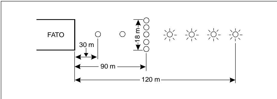
Figure 5-10. Approach lighting system
5.3.3.9 Recommendation.— A suitable brilliancy control should be incorporated to allow for adjustment of light intensity to meet the prevailing conditions.
Note.— The following intensity settings have been found suitable:
a) steady lights — 100 per cent, 30 per cent and 10 per cent; and
b) flashing lights — 100 per cent, 10 per cent and 3 per cent.
5.3.4 Visual alignment guidance system
Application
5.3.4.1 Recommendation.—A visual alignment guidance system should be provided to serve the approach to a heliport where one or more of the following conditions exist especially at night:
a) obstacle clearance, noise abatement or trafi control procedures require a particular direction to be flown;
b) the environment of the heliport provides few visual surface cues; and
c) it is physically impracticable to install an approach lighting system.
Location
5.3.4.2 The visual aligment guidance system sha be located such that a helicopter is guided along the prescribed track towards the FATO.
5.3.4.3 Recommendation.— The system should be located at the downwind edge of the FATO and aligned along the preferred approach direction.
5.3.4.4 The light units shall be frangible and mounted as low as possible.
5.3.4.5 Where the lights of the system need to be seen as discrete sources, light units shall be lcated such that at the extremes of system coverage the angle subtended between units as seen by the pilot shal not be less than 3 minutes of arc.
5.3.4.6 The angles subtended between light units of the system and other units of comparable or greater intensities shall also be not less than 3 minutes of arc.
Note.—Requirements of 5.3.4.5 and 5.3.4.6 can be met for ights on a line normal o the line of sight f the light units are separated by 1 m for every kilometre of viewing range.
Signal format
5.3.4.7 The signal format of the alignment guidance system shall include a minimum of three discrete signal sectors providing "offset to the right", "on track" and "offset to the left" signals.
5.3.4.8 The divergence of the "on track" sector of the system shall be as shown in Figure 5-11.
5.3.4.9 The signal format shall be such that there is no possibility of confusion between the system and any associated visual approach slope indicator or other visual aids.
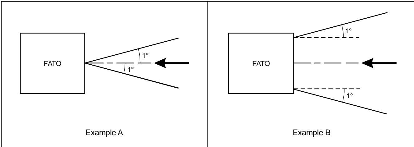
Figure 5-11. Divergence of the “on track'"' sector
5.3.4.10 The system shall avoid the use of the same coding as any associated visual approach slope indicator.
5.3.4.11 The signal format shall be such that the system is unique and conspicuous in all operational environments.
5.3.4.12 The system shall not significantly increase the pilot workload.
Light distribution
5.3.4.13 The usable coverage of the visual alignment guidance system shall be equal to or better than that of the visual approach slope indicator system with which it is associated.
5.3.4.14 A suitable intensity control hall be provided so as to allow adjustment to meet the prevailig conditions and to avoid dazzling the pilot during approach and landing.
Approach track and azimuth setting
5.3.4.15 A visual alignment guidance system shall be capable of adjustment in azimuth to within ±5 minutes of arc of the desired approach path.
5.3.4.16 The angle of the azimuth guidance system shall be such that during an approach the pilot of a helicopter a the boundary of the "on track" signal will clear all objects in the approach area by a safe margin.
5.3.4.17 The characteristics of the obstacle protection surface specified in 5.3.5.23, Table 5-1 and Figure 5-12 shall equally apply to the system.
Characteristics of the visual alignment guidance system
5.3.4.18 In the event of the failure of any component affecting the signal format the system shall be automatically switched off.
Table 5-1. Dimensions and slopes of the obstacle protection surface
| SURFACE AND DIMENSIONS | NON-INSTRUMENT FATO | NON-PRECISION FATO | |
| Length of inner edge | Width of safety area | Width of safety area | |
| Distance from end of FATO | 3 m minimum | 60m | |
| Divergence | 10% | 15% | |
| Total length | 2500m | 2 500m | |
| Slope | PAPI | $\mathrm { A } ^ { \mathrm { a } } - 0 . 5 7 ^ { \circ }$ | $\mathrm { A } ^ { \mathrm { a } } - 0 . 5 7 ^ { \mathrm { o } }$ |
| HAPI | $\mathbf { A } ^ { \mathrm { b } } - 0 . 6 5 ^ { \circ }$ | $\mathrm { A } ^ { \mathrm { b } } - 0 . 6 5 ^ { \circ }$ | |
| APAPI | $\mathrm { A } ^ { \mathrm { a } } - 0 . 9 ^ { \circ }$ | $\mathrm { A } ^ { \mathrm { a } } - 0 . 9 ^ { \circ }$ | |
| a. As indicated in Annex 14, Volume I, Figure 5-13.b. The angle of the upper boundary of the "below slope'"' signal. | |||
5.3.4.19 The light units shal e so designed that deposits of condensation, ice, dirt,etc., on opticall transmitting or reflecting surfaces wil nterfere t the least possible extent with the ight sigal and wil not cause spurius o alse signals tbe generated.
5.3.5 Visual approach slope indicator
Application
5.3.5.1 Recommendation.—A visual approach slope indicator should be provided to serve the approach to a heliport, whether or not the heliport is served by other visual approach aids or by non-visual aids, where one or more of the following conditions exist especially at night:
a) obstacle clearance, noise abatement or traffic control procedures require a particular slope to be flown;
b) the environment of the heliport provides few visual surface cues; and
c) the characteristics of the helicopter require a stabilized approach.
5.3.5.2 The standard visual approach slope indicator systems for helicopter operations shallconsist of the following:
a) PAPI and APAPI systems conforming to the specifications contained in Annex 14, Volume I, 5.3.5.23 to 5.3.5.40 inclusive, except that the angular size of the on-slope sector of the systems shal be increased to 45 minutes; or
b) helicopter approach path indicator (HAPI) system conforming to the specifications in 5.3.5.6 to 5.3.5.21 inclusive.
Location
5.3.5.3 A visual approach slope indicator shall be located such that a helicopter is guided to the desired position within the FATO and so as to avoid dazzling the pilt during final approach and landing.
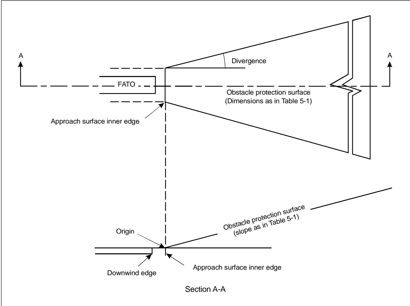
Figure 5-12. Obstacle protection surface for visual approach slope indicator systems
5.3.5.4 Recommendation.—A visual approach slope indicator should be located adjacent t the nominal aiming point and aligned in azimuth with the preferred approach direction.
5.3.5.5 The light unit(s) shall be frangible and mounted as low as possible.
HAPI signal format
5.3.5.6 The signal format of the HAPI shal include four discrete signal sectors, providing an "above slope', an “"on slope", a "slightly below" and a "below slope'"' signal.
5.3.5.7 The signal format of the HAPI shall be as shown in Figure 5-13, Illustrations A and B.
Note.— Care is required in the design of the unit to minimize spurious signals between the signal sectors and at the azimuth coverage limits.
Figure 5-13. HAPI signal format
5.3.5.8 The signal repetition rate of the flashing sector of the HAPI shall be at least 2 Hz.
5.3.5.9 Recommendation.— The on-to-off ratio of pulsing signals of the HAPI should be 1 to 1 and the modulation depth should be at least 80 per cent.
5.3.5.10 The angular size of the "on-slope"” sector of the HAPI shall be 45 minutes.
5.3.5.11 The angular size of the "slightly below' sector of the HAPI shall be 15 minutes.
Light distribution
5.3.5.12 Recommendation.— The light intensity distribution of the HAPI in red and green colours should be as shown in Figure 5-9, Illustration 4.
Note.— A larger azimuth coverage can be obtained by installing the HAPI system on a turntable.
5.3.5.13 Colour transition of the HAPI in the vertical plane shall be such as to appear to an observer at a distance of not less than 300 m to occur within a vertical angle of not more than three minutes.
5.3.5.14 The transmission factor of a red or greenfiter shal be not less than 15 per cent at the maximum intensit setting.
5.3.5.15 At full intensity the red light of the HAPI shall have a Y-coordinate not exceeding 0.320, and the green light shall be within the boundaries specified in Annex 14, Volume I, Appendix 1, 2.1.3.
5.3.5.16 A suitable intensity control hall be provided so as to allow adjustment to meet the prevailig conditions and to avoid dazzling the pilot during approach and landing.
Approach slope and elevation setting
5.3.5.17 A HAPI system shall be capable of adjustment in elevation at any desired angle between 1 degree and 12 degrees above the horizontal with an accuracy of ±5 minutes of arc.
5.3.5.18 The angle of elevation setting of HAPI shall be such that during an approach, the pilot of a helicopter observing the upper boundary of the “below slope'" signal will clear all objects in the approach area by a safe margin.
Characteristics of the light unit
5.3.5.19 The system shall be so designed that:
a) in the event the vertical misalignment of a unit exceeds ±0.5 degrees (±30 minutes), the system will switch off automatically; and
b) if the flashing mechanism fails, no light will be emitted in the failed flashing sector(s).
5.3.5.20 The light unit of the HAPI shall be so designed that deposits of condensation, ice, dirt, etc., on optically transmiting or reflecting surfaces wil interfere to the least possiblextent with th light ignal and wil not cause spurious or false signals to be generated.
5.3.5.21 Recommendation.— A HAPI system intended for installation on a floating helideck should afford a stabilization of the beam to an accuracy of ±1/4 degree within ± 3-degree pitch and roll movement of the helipor.
Obstacle protection surface
Note.— The following specifications apply to PAPI, APAPI and HAPI.
5.3.5.22 An obstacle protection surface shall be established when it is intended to provide a visual approach slope indicator system.
5.3.5.23 The characteristics of the obstacle protection surface, .e. origin, divergence, length and slope, hall corespond to those specified in the relevant column of Table 5-1 and in Figure 5-12.
5.3.5.24 New objects or extensions of existing objects shall not be permited above an obstacle protection surface except when, in the opinion of the appropriate authority, the new object or extension would be shielded by an existing immovable object.
Note.— Circumstances in which the shielding principle may reasonably be applied are described in the Airport Services Manual, Part 6 (Doc 9137).
5.3.5.25 Existing objects above an obstacle protection surface shall be removed except when, in the opinion of the appropriate authority, the objec s shielded by an existing mmovable object, or ater aeronautical study it is determined that the object would not adversely affect the safety of operations of helicopters.
5.3.5.26 Where an aeronautical study indicates that an existing object extending above an obstacle protection surface could adversely affect the safety of operations of helicopters, one or more of the following measures shall be taken:
a) suitably raise the approach slope of the system;
b) reduce the azimuth spread of the system so that the object is outside the confines of the beam;
c) displace the axis of the system and its associated obstacle protection surface by no more than 5 degrees;
d) suitably displace the FATO; and
e) install a visual alignment guidance system specified in 5.3.4.
Note.— Guidance on this issue is contained in the Heliport Manual (Doc 9261).
5.3.6 Final approach and take-off area lights
Application
5.3.6.1 Where a FATO is established at a surface-level heliport on ground intended for use at night, FATO lights shall be provided except that they may be omited where the FATO and th TLOF are nearly coincidental or the extent of the FATO is self-evident.
Location
5.3.6.2 FATO lights shall be placed along the edges of the FATO. The lights shall be uniformly spaced as follows:
a) for an area in the form of a square or rectangle, at intervals of not more than 50 m with a minimum of four lights on each side including a light at each corner; and
b) for any other shaped area, including a circular area, at intervals of not more than 5 m with a minimum of ten lights.
Characteristics
5.3.6.3 FATO lights shall be fixed omnidirectional lights showing white. Where the intensity of the lights is to be varied the lights shall show variable white.
5.3.6.4 Recommendation.— The light distribution of FATO lights should be as shown in Figure 5-9, Ilustration 5.
5.3.6.5 Recommendation.—The lights should not exceed a height of 25 cm and should be inset when a light extending above the surface would endanger helicopter operations. Where a FATO is not meant for iftof or touchdown, the lights should not exceed a height of 25 cm above ground or snow level.
5.3.7 Aiming point lights
Application
5.3.7.1 Recommendation.— Where an aiming point marking is provided at a heliport intended for use at night, aiming point lights should be provided.
Location
5.3.7.2 Aiming point lights shal be collocated with the aiming point marking.
Characteristics
5.3.7.3 Aiming point lights shal form a pattern of at least six omnidirectional whitelights as shown in Figure 5-4. The lights shall be inset when a light extending above the surface could endanger helicopter operations.
5.3.7.4 Recommendation.— The light istribution of aiming point lights should be as shown in Figure 5-9, Ilustration 5.
5.3.8 Touchdown and lift-off area lighting system
Application
5.3.8.1 A TLOF lighting system shall be provided at a heliport intended for use at night.
5.3.8.2 The TLOF lighting system for a surface-level heliport shall consist of one or more of the following:
a) perimeter lights; or
b) floodlighting; or
c) arrays of segmented point source lighting (ASPSL) or luminescent panel (LP) ighting to identify the TLOF when a) and b) are not practicable and FATO lights are available.
5.3.8.3 The TLOF lighting system for an elevated heliport or helideck shall consist of :
a) perimeter lights; and
b) ASPSL and/or LPs to identify the touchdown marking where it is provided and/or floodlighting to iluminate the TLOF.
Note. —At elevated heliports and helidecks, surface texture cues within the TLOF are essential for helicopter positioning during the final approach and landing. Such cues can be provided using various forms of lighting (ASPSL, LP, floodights or a combination of these lights, etc.) in adition to perimeter lights. Best results have been demonstrated by the combination of perimeter lights and ASPSL in the form of encapsulated strips of light emiting diodes (LEDs) to identify the touchdown and heliport identification markings.
5.3.8.4 Recommendation.— TLOF ASPSL and/or LPs to identify the touchdown marking and/ or floodighting should be provided at a surface-level heliport intended for use at night when enhanced surface texture cues are required.
Location
5.3.8.5 TLOF perimeter lights shall be placed along the edge of the area designated for use as the TLOF or within a distance of 1.5 m from the edge. Where the TLOF is a circle the lights shall be:
a) located on straight lines in a pattern which will provide information to pilots on drift displacement; and
b) where a) is not practicable, evenly spaced around the perimeter of the TLOF at the appropriate interval, except that over a sector of 45 degrees the lights shall be spaced at half spacing.
5.3.8.6 TLOF perimeter lights shall be uniformly spaced at intervals of not more than 3 m for elevated heliports and helidecks and not more than 5 m for surface-level heliports. There shall be a minimum number of four lights on each side including a light at each corer. For a circular TLOF, where lights are installed in accordance with 5..8.5 b) there shall be a minimum of fourteen lights.
Note.— Guidance on this issue is contained in the Heliport Manual (Doc 9261).
5.3.8.7 The TLOF perimeter lights shall be instaled at an elevated heliport o fixed helideck such that the pattern cannot be seen by the pilot from below the elevation of the TLOF.
5.3.8.8 The TLOF perimeter lights shall be installed at a floating helideck, such that the pattern canot be seen by the pilot from below the elevation of the TLOF when the helideck is level.
5.3.8.9 On surface-level heliports, ASPSL or LPs, if provided to identify the TLOF, shal be placed along the marking designating the edge of the TLOF. Where the TLOF is a circle, they shall be located on straight lines circumscribing the area.
5.3.8.10 On surface-level heliports the minimum number of LPs on a TLOF shall be nine. The total ength of LPs in a pattern shall not be les than 50 per cent of the length of the patter. There shall be an odd number wit a minimum number of three panels on each side of the TLOF including a panel at each corer. LPs shall be uniformly spaced with a distance between adjacent panel ends of not more than 5 m on each side of the TLOF.
5.3.8.11 Recommendation.— When LPs are used on an elevated heliport or helideck to enhance surface texture cues, the panels should not be placed adjacent to the perimeter ights. They should be placed around a touchdown marking where it is provided or coincident with heliport identification marking.
5.3.8.12 TLOF floodights shall be located so as to avoid glare to pilots i fight or to personnel working on the area. The arrangement and aiming of floodlights shall be such that shadows are kept to a minimum.
Note.— ASPSL and LPs used to designate the touchdown and/or heliport identification marking have been shown to provide enhanced surface texture cues when compared t low-level floodights. Due to the risk of misalignment, if flodlights are used, there wil be a need for them to be checked periodicall to ensure they remain within the specifications contained within 5.3.8.
Characteristics
5.3.8.13 The TLOF perimeter lights shall be fixed omnidirectional lights showing green.
5.3.8.14 At a surface-level heliport, ASPSL or LPs shal emit green light when used to define the perimeter of the TLOF.
5.3.8.15 The provisions of 5.3.8.13 and 5.3.8.14 shall not require the replacement of existing installations before 1 January 2009.
5.3.8.16 Recommendation.— The chromaticity and luminance of colours of LPs should conform to Annex 14, Volume I, Appendix 1, 3.4.
5.3.8.17 An LP shal have a minimum width of 6 cm. The panel housing shall be the same colour as the marking it defines.
5.3.8.18 Recommendation.— The perimeter lights should not exceed a height of 25 cm and should be inset when a light extending above the surface could endanger helicopter operations.
5.3.8.19 Recommendation.— When located within the safety area of a heliport or within the obstacle-fre sector of a helideck, the TLOF floodlights should not exceed a height of 25 cm.
5.3.8.20 The LPs shall not extend above the surface by more than 2.5 cm.
5.3.8.21 Recommendation.— The light distribution of the perimeter ights should be as shown in Figure 5-9, Illustration 6.
5.3.8.22 Recommendation.— The light distribution of the LPs should be as shown in Figure 5-9, Ilustration 7.
5.3.8.23 The spectral disribution of TLOF area floodlights shall be such that the surface and obstacle marking can be correctly identified.
5.3.8.24 Recommendation.— The average horizontal illuminance of the floodighting should be at least 10 lux, with a uniformity ratio (average to minimum) of not more than 8:1 measured on the surface of the TLOF.
5.3.8.25 Recommendation.— Lighting used to identify the touchdown marking should comprise a segmented circle of omnidirectional ASPSL strips showing yellow. The segments should consist of ASPSL strips, and the total length of the ASPSL strips should not be less than 50 per cent of the circumference of the circle.
5.3.8.26 Recommendation.—If utilized, the heliport identification marking lighting should be omnidirectional showing green.
5.3.9 Winching area floodlighting
Application
5.3.9.1 Winching area floodlighting shal be provided at a winching area intended for use at night.
Location
5.3.9.2 Winching area floodlights shall be located so as to avoid glare to pilots in flight or to personnel working on the area. The arrangement and aiming of floodlights shall be such that shadows are kept to a minimum.
Characteristics
5.3.9.3 The spectral distribution of winching area flodlights shall be such that the surface and obstacle markings can be correctly identified.
5.3.9.4 Recommendation.— The average horizontal iluminance should be at least 10 lux, measured on the surface of the winching area.
5.3.10 Taxiway lights
Note.—The specifications for axiway centre line lights and taxiway edge lights in Annex 14, Volume I, 5.3.16 and 5.3.17, are equally applicable to taxiways intended for ground taxing of helicopters.
5.3.11 Visual aids for denoting obstacles
Note.— The specifications for marking and lighting of obstacles included in Annex 14, Volume I, Chapter 6, are equally applicable to heliports and winching areas.
5.3.12 Floodlighting of obstacles
Application
5.3.12.1 At a heliport intended for use at night, obstacles shall be floodighted if it is not possible to display obstacle lights on them.
Location
5.3.12.2 Obstacle floodlights shal be arranged so as t illuminate the entire obstacle and as far as practicable in a manner so as not to dazzle the helicopter pilots.
Characteristics
5.3.12.3 Recommendation.— Obstacle floodlighting should be such as to produce a luminance of at least 10cd/m².
CHAPTER 6. HELIPORT SERVICES
6.1 Rescue and fire fighting
General
Introductory Note.— These specifications apply to surface-level heliports and elevated heliports only. The specifications complement those in Annex 14, Volume I, 9.2, concerning rescue and fire fighting requirements at aerodromes.
The principal objective of a rescue and fire fighting service is to save lives. For this reason, the provision of means of dealing with a helicopter accident or incident occurring at or in the immediate vicinity of a heliport assumes primary importance because it is within his area that there are the greatest opportunitis for saving lives.This must assume at al imes the possibility of, and need for, extinguishing a fire which may occur either immediately fllwing a helicopter accident or incident or at any time during rescue operations.
The most important factors bearing on effective rescue in a survivable helicopter accident are the training received, the effectiveness of the equipment and the speed with which personnel and equipment designated for rescue and fire fighting purposes can be put into use.
For an elevated heliport, requirements to protect any building or structure on which the heliport is located are not taken into account.
Rescue and fire fighting requirements for helidecks may be found in the Heliport Manual (Doc 9261).
Level of protection to be provided
6.1.1 Recommendation.— The level of protection to be provided for rescue and fire fighting should be based on the overallength of the longest helicopter normally using the heliport and in accordance wit the heliport fire fighting category determined from Table 6-1, except at an unattended heliport with a low movement rate.
Note.— Guidance to assist the appropriate authority in providing rescue and fire fighting equipment and services at surface-level and elevated heliports is given in the Heliport Manual (Doc 9261).
Table 6-1. Heliport fire fghting category
| Category | Helicopter overall lengtha |
| H1 | up to but not including 15 m |
| H2 | from 15 m up to but not including 24 m |
| H3 | from 24 m up to but not including 35 m |
| a. Helicopter length, including the tail boom and the rotors. | |
6.1.2 Recommendation.— During anticipated periods of operations by smaller helicopters, the heliport fire fighting category may be reduced to that of the highest category of helicopter planned to use the heliport during that time.
Extinguishing agents
6.1.3 Recommendation.— The principal extinguishing agent should be a foam meting the minimum performance level B.
Note.— Information on the required physical properties and fire extinguishing performance criteria needed for a foam to achieve an acceptable performance level B rating is given in the Airport Services Manual, Part 1 (Doc 9137).
6.1.4 Recommendation.— The amounts of water for foam production and the complementary agents to be provided should be in accordance with the heliport firefighting category determined under6.1.1 and Table 6-2 or Tabl 6-3 as appropriate.
Note.—The amounts of water specified for elevated heliports do not have to be stored on or adjacent to the heliport f there is a suitable adjacent pressurized water main system capable of sustaining the required discharge rate.
Table 6-2. Minimum usable amounts of extinguishing agents for surface-level heliports
| Foam meeting performance level B | Complementary agents | ||||
| Water (L) | Discharge rate foam solution (L/min) | Dry chemical powders (kg) | Halons (kg) | CO2 (kg) | |
| Category (1) | (2) | (3) | (4) | or or (5) | (6) |
| H1 | 500 | 250 | 23 | 23 | 45 |
| H2 | 1000 | 500 | 45 | 45 | 90 |
| H3 | 1600 | 800 | 90 | 90 | 180 |
Table 6-3. Minimum usable amounts of extinguishing agents for elevated heliports
| Foam meeting performance level B | Complementary agents | |||||
| Category | Water (L) | Discharge rate foam solution (L/min) | Dry chemical powders (kg) | Halons (kg) | CO2 (kg) | |
| (1) | (2) | (3) | (4) | or | or (5) | (6) |
| H1 | 2500 | 250 | 45 | 45 | 90 | |
| H2 | 5000 | 500 | 45 | 45 | 90 | |
| H3 | 8000 | 800 | 45 | 45 | 90 | |
6.1.5 Recommendation.—At a surface-lvel heliport it is permissible to replace allor part of the amount of water for foam production by complementary agents.
6.1.6 Recommendation.— The discharge rate of the foam solution should not be less than the rates shown in Table 6-2 or Table 6-3 as appropriate. The discharge rate of complementary agents should be selected for optimum effectivenessof the agent used.
6.1.7 Recommendation.—At an elevated helipor, a least one hose spray line capable of delivering foam in a jet spray pattern at 250 Lmin should be provided. Additionally at eleated heliports in categories 2 and 3, at least two monitors should be provided each having a capabilit of achieving the required discharge rate and positioned at different locations around the heliports so as to ensure the application of foam to any part of the heliport under any weather condition and to minimize the possibility of both monitors being impaired by a helicopter accident.
Rescue equipment
6.1.8 Recommendation.—At an elevated heliport rescue equipment should be stored adjacent to the heliport.
Note.— Guidance on the rescue equipment to be provided at a heliport is given in the Heliport Manual (Doc 9261).
Response time
6.1.9 Recommendation.—At a surface-level heliport, the operational objective of the rescue and fire fighting service should be to achieve response times not exceeding two minutes in optimum conditions of visibility and surface conditions.
Note.— Response time is considered to be the time between the initial call to the rescue and fire fighting service and the time when the first responding vehicle(s) the service) is (are) in position to apply foam at a rate of at least 50 per cent of the discharge rate specified in Table 6-2.
6.1.10 Recommendation.—At an elevated heliport, the rescue and fire fighting service should be immediately available on or in the vicinity of the heliport while helicopter movements are taking place.
APPENDIX 1. AERONAUTICAL DATA QUALITY REQUIREMENTS
Table A1-1. Latitude and longitude
| Accuracy IntegrityLatitude and longitude Data type Classification | ||||
| Heliport reference point | 30m $1 \times 1 0 ^ { - 3 }$ | |||
| Navaids located at the heliport .Obstacles in Area 3. | surveyed/calculated routine | |||
| 3m $1 \times 1 0 ^ { - 5 }$ | ||||
| Obstacles in Area 3. | surveyed essential | |||
| 0.5m $1 \times 1 0 ^ { - 5 }$ | ||||
| Obstacles in Area 2 (the part within the heliport boundary)Geometric centre of TLOF or FATO thresholds . | surveyed essential | |||
| 5m $1 \times 1 0 ^ { - 5 }$ | ||||
| surveyed essential | ||||
| 1m $1 \times 1 0 ^ { - 8 }$ | ||||
| Ground taxiway centre line points, air taxiway and transit route pointsGround taxiway intersection marking line | surveyed critical | |||
| 0.5m $1 \times 1 0 ^ { - 5 }$ | ||||
| surveyed/calculated | essential | |||
| 0.5m | $1 \times 1 0 ^ { - 5 }$ | |||
| Ground exit guidance line | surveyed | essential | ||
| 0.5m | $1 \times 1 0 ^ { - 5 }$ | |||
| Apron boundaries (polygon)De-icing/anti-icing facility (polygon)Helicopter standpoints/INS checkpoints | surveyed | essential | ||
| 1m | $1 \times 1 0 ^ { - 3 }$ | |||
| surveyed | routine | |||
| 1m | $1 \times 1 0 ^ { - 3 }$ | |||
| surveyed | routine | |||
| 0.5m | $1 \times 1 0 ^ { - 3 }$ | |||
| surveyed routine | ||||
Table A1-2. Elevation/altitude/height
| Elevation/altitude/height | Accuracy Data type | Integrity Classification |
| Heliport elevation …… | 0.5m surveyed | $1 \times 1 0 ^ { - 5 }$ essential |
| WGS-84 geoid undulation at heliport elevation position …… | 0.5 m surveyed | $1 \times 1 0 ^ { - 5 }$ essential |
| FATO threshold, non-precision approaches … | 0.5m surveyed | $1 \times 1 0 ^ { - 5 }$ essential |
| WGS–84 geoid undulation at FATO threshold, TLOF geometric centre, non-precision approaches .. | 0.5m surveyed | $1 \times 1 0 ^ { - 5 }$ essential |
| FATO threshold, precision approaches …. | 0.25m surveyed | $1 \times 1 0 ^ { - 8 }$ critical |
| WGS–84 geoid undulation at FATO threshold, TLOF geometric centre, precision approaches … | 0.25m | $1 \times 1 0 ^ { - 8 }$ |
| Ground taxiway centre line points, air taxiway and transit route points | surveyed 1m | critical $1 \times 1 0 ^ { - 5 }$ |
| Obstacles in Area 2 (the part within the heliport boundary) | surveyed 3m | essential $1 \times 1 0 ^ { - 5 }$ |
| Obstacles in Area 3 .. | surveyed 0.5m | essential $1 \times 1 0 ^ { - 5 }$ |
| Distance measuring equipment/precision (DME/P) … | surveyed 3m surveyed | essential $1 \times 1 0 ^ { - 5 }$ essential |
Note 1.—See Annex 15, Appendix8, for graphical ilustrations of obstacle data collection surfaces and criteria used to identify obstacles in the defined areas.
Note 2.—Implementation of Annex 15, provision 10.6.1.2, concerning the availability, as of 18November 2010, of obstacle data according toArea 2 and Area 3 specifications would be facilitated by appropriate advance planning for the colletion and processing of such data.
Table A1-3. Declination and magnetic variation
| Declination/variation | Accuracy Data type | Integrity Classfication |
| Heliport magnetic variation | 1 degree | $1 \times 1 0 ^ { - 5 }$ |
| surveyed | essential | |
| ILS localizer antenna magnetic variation | 1 degree | $1 \times 1 0 ^ { - 5 }$ |
| surveyed | essential | |
| 1 degree | $1 \times 1 0 ^ { - 5 }$ | |
| surveyed | essential |
Table A1-4. Bearing
| Bearing | Accuracy Data type | Integrity Classification |
| ILS localizer alignment . | 1/100 degree surveyed | $1 \times 1 0 ^ { - 5 }$ essential |
| MLS zero azimuth alignment …. | 1/100 degree surveyed | $1 \times 1 0 ^ { - 5 }$ essential |
| 1/100 degree surveyed | $1 \times 1 0 ^ { - 3 }$ routine |
Table A1-5. Length/distance/dimension
| Accuracy IntegrityLength/distance/dimension Data type Classifi cation | |||
| FATO length, TLOF dimensions …… Clearway length and width | 1m $1 \times 1 0 ^ { - 8 }$ | ||
| surveyed critical | |||
| 1m $1 \times 1 0 ^ { - 5 }$ | |||
| Landing distance available | surveyed essential | ||
| 1m $1 \times 1 0 ^ { - 8 }$ | |||
| Take-off distance available | surveyed critical | ||
| 1m $1 \times { 1 0 } ^ { - 8 }$ | |||
| Rejected take-off distance available | |||
| surveyed critical | |||
| 1m $1 \times 1 0 ^ { - 8 }$ | |||
| surveyed critical | |||
| Taxiway width | |||
| 1m $1 \times 1 0 ^ { - 5 }$ | |||
| ILS localizer antenna-FATO end, distance . | |||
| surveyed essential | |||
| 3m $1 \times 1 0 ^ { - 3 }$ | |||
| ILS glide slope antenna-threshold, distance along centre line . | calculated routine3m $1 \times { 1 0 } ^ { - 3 }$ | ||
| ILS marker-threshold distance …… | calculated | routine | |
| 3m | $1 \times 1 0 ^ { - 5 }$ | ||
| calculated3m | essential | ||
| ILS DME antenna-threshold, distance along centre line … | |||
| $1 \times 1 0 ^ { - 5 }$ | |||
| calculated3m | essential | ||
| MLS azimuth antenna-FATO end, distance . | |||
| $1 \times 1 0 ^ { - 3 }$ | |||
| calculated3m | routine | ||
| MLS elevation antenna-threshold, distance along centre line .. | |||
| $1 \times 1 0 ^ { - 3 }$ | |||
| MLS DME/P antenna-threshold, distance along centre line | calculated3m | routine | |
| $1 \times 1 0 ^ { - 5 }$ | |||
| calculated | essential | ||