ICAO Doc 9261 Heliport Manual (5th ed.)
Doc 9261
Heliport Manual
Fifth Edition, 2021

Approved by and published under the authority of the Secretary General
INTERNATIONAL CIVIL AVIATION ORGANIZATION
Doc 9261
Heliport Manual
Fifth Edition, 2021
Approved by and published under the authority of the Secretary General
Published in separate English, Arabic, Chinese, French, Russian and Spanish editions by the INTERNATIONAL CIVIL AVIATION ORGANIZATION 999 Robert-Bourassa Boulevard, Montréal, Quebec, Canada H3C 5H7
For ordering information and for a complete listing of sales agents and booksellers, please go to the ICAO website at www.icao.int
Third edition, 1995
Fourth edition, 2020
Fifth edition, 2021
Doc 9261, Heliport Manual
Order Number: 9261
ISBN 978-92-9265-356-9
© ICAO 2021
All rights reserved. No part of this publication may be reproduced, stored in a retrieval system or transmitted in any form or by any means, without prior permission in writing from the International Civil Aviation Organization.
AMENDMENTS
Amendments are announced in the supplements to the Products and Services Catalogue; the Catalogue and its supplements are available on the ICAO website at www.icao.int. The space below is provided to keep a record of such amendments.
RECORD OF AMENDMENTS AND CORRIGENDA
| AMENDMENTS | CORRIGENDA | |||||||
| No. | Date | Entered by | No. | Date | ||||
FOREWORD
The Heliport Manual (Doc 9261) is divided into two parts to address helicopter landing areas at a range of offshore installations and vessels (Part I), as distinct from the heliports used in the onshore environment (Part II).
Although not exclusively the case, the types of facilities illustrated in Part I are typically used in the process of mineral extraction and for the exploration and/or exploitation of oil and/or gas in the offshore environment. Increasingly, however, installations equipped with helicopter landing areas are being used to service the offshore renewable energy sector, e.g. a substation with helideck is used as a base for helicopters shuttling around a wind farm. Although the current method of personnel transfer from a helicopter to a wind turbine (nacelle) tends to be helicopter hoist operations (HHO), rather than land-on operations, it is possible that in the future, considering the development of yet-larger wind turbines, some turbines may be equipped with helicopter landing areas that allow maintenance personnel to land on the turbine in the same way that a helicopter would land on an oil or gas facility.
Part II deals with two principal types of heliports: surface level heliports and elevated heliports. It also provides guidance on aspects not included in Annex 14, Volume II, e.g. site selection, site management and safeguarding, the design helicopter, surface loading, vertical procedures and virtual clearways.
Users of this manual are advised that specifications related to helicopter operations in other Annexes, for instance, Annex 6 — Operation of Aircraft, Part III — International Operations — Helicopters, may vary somewhat from those specified in Annex 14, Volume II. In such cases, the more demanding requirements should be applied. To assist users, the characteristics of the majority of helicopter types currently in use are considered in Part II, Appendix A, Chapter 3 of this manual.
Acknowledgements
ICAO wishes to acknowledge the dedicated work of the offshore subgroup of the Heliport Design Working Group (HDWG) of the ICAO Aerodrome Design and Operations Panel (ADOP) in developing the contents of this manual.
Future developments
Part I — Offshore Heliports and Part II — Onshore Heliports represent the first stage in the modernization and updating of the Heliport Manual in light of the substantial development of Annex 14 — Aerodromes, Volume II — Heliports in recent years, and of the equipment, technology and best practices used by the heliports arena.
The content of this manual should not be taken as contradicting or conflicting with Annex 14 provisions or any other Standards, Recommended Practices, procedures or guidance material published by ICAO. The guidance material in this manual will be updated at regular intervals. Comments on this manual would be appreciated from all parties involved in heliport design, construction, safety oversight and operations. These comments should be addressed to:
The Secretary General
International Civil Aviation Organization
999 Robert-Bourassa Boulevard
Montréal, Quebec, Canada H3C 5H7
icaohq@icao.int
TABLE OF CONTENTS
Page
Glossary (ix)
Explanation of terms ..... ....................................................................................................... (ix)
Abbreviations/acronyms . ....................................................................................................... (xiii)
References .. ............................................................................ (xvii)
PART I. OFFSHORE HELIPORTS
CHAPTER 1. General . ..... I-1-1
1.1 Introduction .... ............................................. I-1-1
1.2 Helidecks ... .............................................................. I-1-2
1.3 Shipboard heliports... ............................................ I-1-6
1.4 Table of characteristics for common offshore helicopter types . ............................................. I-1-10
CHAPTER 2. Heliport data .... ............................................ I-2-1
2.1 Introduction .. I-2-1
2.2 Authorization of offshore heliports – assessment checklist, content of a helideck directory (HD)
and content of a helideck information plate (HIP) .. I-2-1
CHAPTER 3. Physical characteristics .. ...... I-3-1
3.1 Helideck and purpose-built shipboard heliport structural design . ..... I-3-1
3.2 Helideck/shipboard heliport design considerations — including environmental effects ................ I-3-4
3.3 Guidance on helideck size and surface mounted objects ....... .............. I-3-10
3.4 Shipboard heliport size and surface-mounted objects . ....................................................... I-3-12
3.5 Helideck surface arrangements . ............................................ I-3-14
3.6 Shipboard heliport surface arrangements .. .......................................................... I-3-17
CHAPTER 4. Obstacle environment.. ..... I-4-1
4.1 Description of surfaces — helidecks.. ..... I-4-1
4.2 Description of surfaces — shipboard heliports . ......................................... I-4-2
4.3 Temporary combined operations . ......................................... I-4-3
4.4 Multiple platform configurations/location of standby vessels . ............................. I-4-4
4.5 Guidance for obstacle-protected surfaces for square or circular helidecks . .......................... I-4-4
4.6 Mapping of obstacles on non-purpose-built shipboard heliports .. ..... I-4-5
CHAPTER 5. Visual aids — Marking and lighting.. ....... I-5-1
5.1 General....... ....................................................................................... I-5-1
5.2 Wind direction indicator .... .............................................................................................. I-5-2
5.3 Heliport identification (H) marking . ...... ............................................... ................... I-5-2
5.4 Maximum allowable mass marking.. ................................................................................... I-5-3
5.5 D-value markings . ................................................................................ I-5-4
5.6 TLOF perimeter marking .. ................................................................................. I-5-5
5.7 Touchdown/positioning marking circle... ............................................................................... I-5-5
5.8 Heliport name marking ............. ................................................................... I-5-6
5.9 Helideck obstacle-free sector (chevron) marking . .................................................................. I-5-7
5.10 Helideck and shipboard heliport surface marking.. .................................................................... I-5-7
5.11 Prohibited landing sector marking ... .................................................... I-5-8
5.12 General considerations for lights including screening.. I-5-8
5.13 TLOF lighting systems utilizing floodlight solutions . I-5-9
5.14 TLOF lighting systems utilizing “H” and circle lighting — details of a scheme first adopted
in the United Kingdom .... ......... I-5-10
5.15 Lighting systems — special considerations for non-purpose-built shipboard heliports...... ....... I-5-10
5.16 Visual aids for denoting obstacles — marking and lighting (including floodlighting) .. I-5-11
CHAPTER 6. Helideck rescue and firefighting facilities.. ........ I-6-1
6.1 Introduction... ......... ....... I-6-1
6.2 Key design characteristics — principal agent ... ..................................................................... I-6-1
6.3 Use and maintenance of foam equipment .. ....................................................................... I-6-5
6.4 Complementary media . .................................................................. I-6-5
6.5 Not permanently attended installations (NPAIs) .. ................................................................... I-6-6
6.6 The management of extinguishing media stocks... ......... I-6-7
6.7 Rescue equipment.......... ............................................................................... I-6-7
6.8 Personnel levels . I-6-7
6.9 Personal protective equipment (PPE).. ............................................................................... I-6-8
6.10 Training .... ............................................................................... I-6-8
6.11 Emergency procedures ................................................................................................................ I-6-9
CHAPTER 7. Winching areas on ships .. ...... ......... I-7-1
7.1 General considerations including location, physical characteristics and obstacle protection........ I-7-1
7.2 Marking of a winching area...... .................... ............................ I-7-2
7.3 Lighting of a winching area for night heli-hoist operations. ...... ..... ........ .................. I-7-4
7.4 Additional operational considerations. ............................ I-7-4
CHAPTER 8. Miscellaneous items . ................................................................... I-8-1
8.1 Criteria for parking areas and push-in parking areas...................................................................... I-8-1
8.2 Meteorological equipment provision ..... ...................................................................... I-8-9
8.3 Deck motions reporting and recording............................................................................................ I-8-10
8.4 Communications and navigation equipment.. .................................................................... I-8-11
8.5 Helicopter refuelling operations .. ........ ................................................... I-8-11
8.6 Bird control at normally unattended offshore facilities . I-8-12
APPENDICES TO PART I
APPENDIX I-A. Sample risk assessment for helicopter operations to helidecks and shipboard heliports
which are sub-1D... I-App A-1
APPENDIX I-B. Specification for helideck lighting scheme comprising: perimeter lights, lit
touchdown/positioning marking and lit heliport identification marking ...... I-App B-1
APPENDIX I-C. Drainage calculation .... I-App C-1
PART II. ONSHORE HELIPORTS
CHAPTER 1. Historical background . ..... II-1-1
1.1 Introduction.. ............................................................................................ II-1-1
1.2 Scope and purpose . ........................................................................ II-1-1
1.3 Contents of document . ........................................................................ II-1-2
CHAPTER 2. Site selection, management and heliport data . ..................................................... II-2-1
2.1 Site selection and management . ......................................................................................... II-2-1
2.2 Heliport data . ....................................................................................... II-2-7
2.3 Certification of heliports .... ...................................................................................................... II-2-8
2.4 Safety management system ......................................................................................................... II-2-8
2.5 Heliport winterization .. .................................................................................................. II-2-8
2.6 Safeguarding of heliports... .................................................................................... II-2-8
2.7 Inspector qualifications and training ............................................................... II-2-9
CHAPTER 3. Physical characteristics of onshore heliports.... .......................................................... II-3-1
3.1 General... ..................................................................... II-3-1
3.2 FATO.. .............................................................................. II-3-9
3.3 TLOF . ................................................................................ II-3-21
3.4 Helicopter taxiways and taxi-routes. ....................................................................................... II-3-25
3.5 Aprons and stands .... ............................................................................................ II-3-27
CHAPTER 4. Obstacle environment.... ................................................................................................... II-4-1
4.1 Obstacle limitation surfaces and sectors . ............................................................................. II-4-1
4.2 Application of obstacle limitations..... .................................................................................... II-4-11
CHAPTER 5. Visual aids .... ............................................................................. II-5-1
5.1 Indicators ..... .................................................................................................................... II-5-1
5.2 Marking aids ..... ........................................................................................................................... II-5-2
5.3 Lights... ................................................................................................................. II-5-18
Page
CHAPTER 6. Heliport emergency response ... II-6-1
6.1 Heliport emergency planning .... II-6-1
6.2 Rescue and firefighting service (RFFS) ............... ......... II-6-3
APPENDICES TO PART II
APPENDIX A TO CHAPTER 2. Sample aviation safeguarding procedure .... . II-2-App A-1
APPENDIX A TO CHAPTER 3. The design helicopter .. .. II-3-App A-1
APPENDIX B TO CHAPTER 3. Surface loading ... .. II-3-App B-1
APPENDIX C TO CHAPTER 3. Establishing the rejected take-off distance ...... .. II-3-App C-1
APPENDIX D TO CHAPTER 3. Establishing a virtual clearway ... ......... II-3-App D-1
APPENDIX A TO CHAPTER 4. Elevating the origin of the take-off climb or approach surfaces
and utilizing PC1 vertical procedures .... . II-4-App A-1
APPENDIX B TO CHAPTER 4. Single take-off and climb and approach surface . . II-4-App B-1
APPENDIX A TO CHAPTER 5. Visual alignment guidance system .. . II-5-App A-1
APPENDIX B TO CHAPTER 5. Helicopter approach path indicator .. ..... II-5-App B-1
APPENDIX C TO CHAPTER 5. Example of the UK specification for a hospital heliport
lighting system . .. II-5-App C-1
APPENDIX A TO CHAPTER 6. Example of a task/resource analysis (TRA) . . II-6-App A-1
APPENDIX B TO CHAPTER 6. Certification status (crashworthiness) ....... ....... II-6-App B-1
GLOSSARY
EXPLANATION OF TERMS
Category A. With respect to helicopters, a multi-engined helicopter designed with engine and system isolation features specified in Annex 8 — Airworthiness of Aircraft, Part IVB, and capable of operations using take-off and landing data scheduled under a critical engine failure concept which assures adequate designated surface area and adequate performance capability for continued safe flight or safe rejected take-off.
Category B. With respect to helicopters, a single engine or multi-engined helicopter which does not meet Category A standards. Category B helicopters have no guaranteed capability to continue safe flight in the event of an engine failure, and a forced landing is assumed.
Commercial air transport operation. An aircraft operation involving the transport of passengers, cargo or mail for remuneration or hire.
Congested area. In relation to a city, town or settlement, any area which is substantially used for residential, commercial or recreational purposes.
D. The largest overall dimension of the helicopter, when rotor(s) are turning, measured from the most forward position of the main rotor tip path plane to the most rearward position of the tail rotor tip path plane or helicopter structure. D is sometimes referred to as D-value.
Distance DR. The horizontal distance that a helicopter has travelled from the end of the take-off distance available.
D-Value. A limiting dimension, in terms of D, for a heliport, helideck or shipboard heliport, or for a defined area within.
Design helicopter. The helicopter type having the largest overall length and greatest maximum certificated take-off mass for which a helideck or shipboard heliport has been designed. Both attributes may not reside in the same helicopter.
Dynamic load-bearing surface. A surface capable of supporting the loads generated by a helicopter in motion.
Essential objects permitted. Includes, but may not be limited to: around the touchdown and lift-off area (TLOF): perimeter lights and floodlights, guttering and raised kerb, foam monitors or ring-main system, handrails and associated signage, other lights; on the TLOF: helideck net and helideck touchdown marking (“H” and “circle”) lighting; and in the area between the TLOF perimeter and the FATO perimeter, helideck safety netting is present (for helideck installations completed on or before 1 January 2012, this is permitted to exceed the TLOF surface by 25 cm (10 in)). For helidecks completed after 1 January 2012, the outboard edge of netting should be flush, level with the TLOF (for shipboard heliports the effective date is 1 January 2015)).
Elevated heliport. A heliport located on a raised structure on land.
En-route phase. That part of the flight from the end of the take-off and initial climb phase to the commencement of the approach and landing phase.
Note.— Where adequate obstacle clearance cannot be guaranteed visually, flights must be planned to ensure that obstacles can be cleared by an appropriate margin. In the event of failure of the critical engine, operators may need to adopt alternative procedures.
Exposure. Any part of a flight during which a system or engine failure leading to a forced landing is likely to result in a hazardous or catastrophic outcome.
Exposure time. The period during which the performance of the helicopter with the critical engine inoperative in still air does not guarantee a safe forced landing or the safe continuation of the flight.
Falling gradient. A surface extending downwards on a gradient of 5:1 measured from the edge of the safety netting (or shelving) located around the TLOF below the elevation of the helideck or shipboard heliport to water level for an arc of not less than 180 degrees, which passes through the centre of the TLOF and outwards to a distance that will allow for safe clearance of obstacles below the TLOF in the event of an engine failure for the type of helicopter the helideck or shipboard heliport is intended to serve. Where high-performing helicopters are exclusively used, consideration may be given to relaxing the falling gradient from a 5:1 to a 3:1 slope.
FATO. A defined area over which the final phase of the approach manoeuvre to hover or land is completed and from which the take-off manoeuvre is commenced. Where the FATO is to be used by helicopters operating in performance Class 1, the defined area includes the rejected take-off area available.
Hazard. A condition or an object with the potential to cause or contribute to an aircraft incident or accident.
Helideck. A heliport located on a fixed or floating offshore facility such as an exploration and/or production unit used for the exploitation of oil and gas.
Heliport elevation. The highest point of the final approach and take-off area (FATO).
Landing distance available (LDAH). The length of the final approach and take-off area plus any additional area declared available and suitable for helicopters to complete the landing manoeuvre from a defined height.
Landing distance required (LDRH). The horizontal distance required to land and come to a full stop from a point 15 m (50 ft) above the landing surface.
Landing decision point (LDP). The point used in determining landing performance from which, an engine failure occurring at this point, the landing may be safely continued or a balked landing initiated.
Note.— LDP applies only to helicopters operating in performance Class 1.
Limited obstacle sector(s). A sector, not greater than 150 degrees, within which obstacles may be permitted, provided the height of the obstacles is limited.
Limited-sized heliport. For the purpose of establishing an RFFS, a heliport where the firefighting capacity is concentrated at the FATO/TLOF and there is no requirement to move foam and/or water dispensing equipment.
Obstacle. All fixed (whether temporary or permanent) and mobile objects, or parts thereof, that: are located on an area intended for the surface movement of helicopters; extend above a defined surface intended to protect helicopters in flight; or stand outside those defined surfaces but nonetheless are assessed as a hazard to air navigation.
Obstacle-free sector. A sector, not less than 210 degrees, extending outwards to a distance that will allow for an unobstructed departure path appropriate to the helicopter the TLOF is intended to serve, within which no obstacles above the level of the TLOF are permitted (for helicopters operated in PC1 or PC2 the horizontal extent of this distance will be compatible with the one-engine inoperative capability of the helicopter type to be used).
Operations in Performance Class 1 (PC1). Operations with performance such that, in the event of a critical engine failure, performance is available to enable the helicopter to safely continue the flight to an appropriate landing area, unless the failure occurs prior to reaching the take-off decision point (TDP) or after passing the landing decision point (LDP), in which cases the helicopter must be able to land within the rejected take-off or landing area.
Operations in Performance Class 2 (PC2). Operations with performance such that, in the event of critical engine failure, performance is available to enable the helicopter to safely continue the flight to an appropriate landing area, except when the failure occurs early during the take-off manoeuvre or late in the landing manoeuvre, in which cases a forced landing may be required.
Operations in Performance Class 3 (PC3). Operations with performance such that, in the event of an engine failure at any time during the flight, a forced landing will be required.
Purpose-built heliport. A specifically designed structure, normally fabricated from aluminium or steel, put in place for the purpose of operating helicopters.
Note.— A non-purpose-built heliport is part of an existing structure (such as a building) that is utilised for the purpose of operating helicopters.
Rejected take-off distance required (RTODRH). The horizontal distance required from the start of the take-off to the point where the helicopter comes to a full stop following an engine failure and rejection of the take-off at the take-off decision point.
Rejected take-off distance available (RTODAH). The length of the final approach and take-off area declared available and suitable for helicopters operating in Performance Class 1 to complete a rejected take-off.
Safe forced landing. Unavoidable landing or ditching with a reasonable expectancy of no injuries to persons in the aircraft or on the surface.
Shipboard heliport. A heliport located on a ship that may be purpose-built or non-purpose-built. A purpose built shipboard heliport is one designed specifically for helicopter operations. A non-purpose-built shipboard heliport is one that utilizes an area of the ship that is capable of supporting a helicopter but is not designed specifically for it.
Static load-bearing area. A surface capable of supporting the mass of the helicopter situated upon it.
Take-off and initial climb phase. That part of the flight from the start of take-off to 300 m (1 000 ft) above the elevation of the FATO, if the flight is planned to exceed this height, or to the end of the climb in the other cases.
Take-off decision point (TDP). The point used in determining take-off performance from which, an engine failure occurring at this point, either a rejected take-off may be made or a take-off safely continued.
Note.— TDP applies only to helicopters operating in Performance Class 1.
Take-off distance available (TODAH). The length of the final approach and take-off area plus the length of any clearway (if provided) declared available and suitable for helicopters to complete the take-off.
Take-off distance required (TODRH). The horizontal distance required from the start of the take-off to the point at which VTOSS, a selected height and a positive climb gradient are achieved, following failure of the critical engine being recognized at TDP, the remaining engines operating within approved operating limits.
Note.— The selected height stated above is to be determined with reference to either:
a) the take-off surface; or
b) a level defined by the highest obstacle in the take-off distance required.
Take-off flight path. The vertical and horizontal path, with the critical engine inoperative, from a specified point in the take-off to 300 m (1 000 ft) above the take-off surface.
TLOF. An area on which a helicopter may touchdown or lift-off.
Touchdown/positioning marking circle. The TD/PM circle is the reference marking for a normal touchdown, so located that when the pilot’s seat is over the marking, the whole of the undercarriage will be within the TLOF and all parts of the helicopter will be clear of any obstacles by a safe margin.
Winching area. An area provided for the hoist transfer by helicopter of personnel or stores to and from a ship.
µ. The coefficient of friction, Mu, is the ratio between the friction force and the vertical load.
ABBREVIATIONS/ACRONYMS
| AC | Advisory circular (FAA) |
| AEO | All engines operating |
| AFFF | Aqueous film forming foam |
| AMSL | Above mean sea level |
| APAPI | Abbreviated precision approach path indicator |
| ASPSL | Arrays of segmented point source lighting |
| ATEX | Equipment for potentially explosive atmospheres |
| ATT | Along-track tolerance |
| BCAFS | Performance Level B foam |
| BS | British Standard |
| CAFS | Compressed air foam system |
| CAT | Commercial air transport |
| CRFS | Crash resistant fuel system |
| cd | Candela |
| CFD | Computational fluid dynamics |
| C/L cm | Centre line |
| CZ | Centimetre |
| D | Clear zone |
| DIFF | Maximum dimension of helicopter |
| DIFFS | Deck integrated firefighting |
| DP | Deck integrated firefighting system |
| DPS | Decision point |
| DR | Dynamic positioning system Horizontal distance that the helicopter has travelled from the end of the take-off distance available |
| EASA | |
| EN | European Union Aviation Safety Agency |
| EPNdB | European number Effective perceived noise in decibels |
| FAA | Federal Aviation Administration |
| FAS | Fixed application system |
| FATO | Final approach and take-off area |
| FFAS | Fixed foam application system |
| FFS | |
| FMS | Firefighting service |
| FOD | Fixed monitor system Foreign object debris |
| FOV | |
| FPSO | Field of view |
| FSO | Floating production storage and offloading |
| ft | Floating storage and offloading Feet |
| FPM | Feet per minute |
| GPU | Ground power unit |
| HAPI | Helicopter approach path indicator |
| HEMS | Helicopter emergency medical services |
| HD | Helideck directory |
| HDA | Helideck assistant |
| HDWG | Heliport design working group |
| HHO | Helicopter hoist operations |
| HIP | Helideck information plate |
| HLO | Helicopter landing officer |
| HMS | Helideck motion system |
| HRP | Heliport reference point |
HV Height velocity
ICAO International Civil Aviation Organization
ICS International Chamber of Shipping
IDF Initial departure fix
IEC International Electrotechnical Commission
ILS Instrument landing system
in Inches
IMO International Maritime Organization
IP International Protection
ISO International Organization for Standardization
kg Kilogram
km.h Kilometres per hour
Kts Knots
l Litre
lb(s) Pound(s)
LDAH Landing distance available (for helicopters)
LDP Landing decision point
LDRH Landing distance required (for helicopters)
LED Light emitting diode
LFL Lower flammable limit
LNG Liquefied natural gas
LOA Limited obstacle area
LOS Limited obstacle sector
LP Luminescent panel
LPA Limited parking area
lx lux
m Metre
MAPt Missed approach point
MCA Minimum crossing altitude
MLS Microwave landing system
mm Millimetre
MMMF Man-made mineral fibres
MODU Mobile offshore drilling unit
MR Main rotor
MRCA Minimum rotorcraft containment area
MTOM Maximum take-off mass
MZ Manoeuvring zone
N Newton
NDB Non-directional beacon
NFPA National Fire Protection Association
NM Nautical miles
NOTAM Notice to airmen
NPAI Not permanently attended installation
NVIS Night vision imaging system
OCA Obstacle clearance altitude
OCL Obstacle clearance level
OCS Obstacle clearance surface
OEI One engine inoperative
OFS Obstacle-free sector
OIS Obstacle identification surface
OLS Obstacle limitation surface
PAI Permanently attended installation
PAPI Precision approach path indicator
PC Performance class
PC1 Performance Class 1
PC2 Performance Class 2
PC3 Performance Class 3
PCF Post-crash fire
PDG Procedure design gradient
PFAS Portable foam application system
PinS Point in space
PIPA Push-in parking area
PLS Prohibited landing sector
PPE Personal protective equipment
PTA Parking transition area
kN/m2 Kilonewton per square metre
QFE Query: field elevation
QNH Query: nautical height
RAO Response amplitude operator
RO Radio operator
RD Rotor diameter
RFFR Rescue and firefighting response
RFFS Rescue and firefighting services
RFM Rotorcraft Flight Manual
RMS Ring-main system
ROD Rate of descent
ROTS Remotely operated TV system
RPE Respiratory protective equipment
R/T Radio-telephony or radio communications
RTOD Rejected take-off distance
RTODAH Rejected take-off distance available (for helicopters)
RTODRH Rejected take-off distance required available (for helicopters)
s Second
SA Safety area
SAR Search and rescue
SARPs Standards and Recommended Practices
SFL Safe forced landing
SLS Serviceability limit states
SMS Safety management system
SRF Structural response factor
SRM Safety risk management
SSP State safety program
t Tonne (1000 kg)
TDP Take-off decision point
TDPC Touchdown positioning circle
TD/PM Touchdown/positioning marking
TLOF Touchdown and lift-off area
TLS Target level of safety
TMA/TCA Terminal manoeuvring area (terminal control area)
TODAH Take-off distance available (for helicopters)
TODRH Take-off distance required (for helicopters
TRA Task/resource analysis
UCW Undercarriage width
ULS Ultimate limit states
UPS Uninterrupted power supply
UV Ultraviolet
VFR Visual flight rules
VMC Visual meteorological conditions
VSDA Visual segment design angle
VSDG Visual segment design gradient
VTOSS Take-off safety speed for helicopters certificated in category A
WAT Weight/altitude/temperature
XTT Cross-track tolerance
REFERENCES
Air Transport Association Specification 103 (Standard for Jet Fuel Quality Control at Airports)
International Chamber of Shipping (ICS) Helicopter/Ship Guide to Operations, 4th Edition, 2008
International Convention for the Prevention of Pollution from Ships (MARPOL)
International Convention for the Safety of Life at Sea (SOLAS)
International Maritime Organization (IMO) Code for the Construction and Equipment of Mobile Offshore Drilling Units (MODU)
PART I
OFFSHORE HELIPORTS
Chapter 1
GENERAL
1.1 INTRODUCTION
Offshore heliports, even when confined to mineral extraction activities, employ a wide range of offshore landing facilities, including helidecks on fixed platforms, mobile offshore drilling units, crane barges and floating production storage and offloading (FPSO) units, and purpose-built shipboard heliports located on large tankers or on smaller vessels such as diving support vessels, seismic survey vessels, ice-breakers and research vessels. For vessels, in particular, helicopter landing areas may be purposebuilt above the bow or stern, purpose-built in an amidships location, or purpose-built overhanging the ship’s side. This manual also provides information for non-purpose-built shipboard heliports, whether located on the side of a ship (ship’s side) or on other areas not specifically designed to receive helicopters, such as hatch covers (Figure I-1-9. refers). Finally, the document addresses shipboard winching areas, where a helicopter hoist operation (HHO) is completed in lieu of landing. The operation of non-purpose-built shipboard heliports and shipboard winching areas is described in detail in the International Chamber of Shipping (ICS) Helicopter/Ship Guide to Operations, 4th Edition, 2008.
1.2 HELIDECKS
1.2.1 Fixed platforms (permanently attended and not permanently attended)
Fixed platforms sit directly on the sea floor and are thus stable. They can be single units or can consist of two or more separate modules for production, processing and accommodation. Separate modules are generally linked by bridges and can be served by more than one helideck. Fixed platforms that are occupied year-round are often referred to as permanently attended installations (PAI), while those facilities that do not subscribe to a permanent attendance model are referred to in this manual as not permanently attended installations (NPAIs). The acronyms PAI and NPAI are used throughout this document, although it is appreciated that individual States may use additional or alternative acronyms to describe particular attendance models to distinguish specific levels of occupancy of offshore facilities.
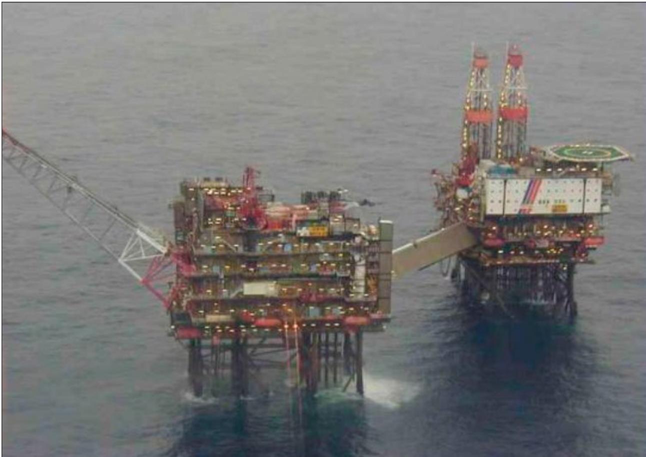
Figure I-1-1. A fixed platform with helideck above accommodation, bridge linked to a production platform
1.2.2 Mobile offshore drilling units: semi-submersible
Semi-submersible units have the hull design of a catamaran and are either towed or self-propelled. A semi-submersible unit has good stability and sea-keeping characteristics and can be positioned dynamically with thrusters or by the use of anchors. These units are heavy duty specialized rigs, with their hull structure submerged at a deep draft (ballasted down fifty feet or more to give it stability) so that a semi-submersible unit, being less affected by wave loadings than a normal ship, is able to operate in adverse weather conditions. They are used in a number of specific offshore roles, such as offshore drilling rigs and heavy lift cranes. In the latter case, a semi-submersible unit is able to transform from a deep to a shallow draft rig by de-ballasting (removing ballast water from the hull), thereby becoming a surface vessel. Semi-submersibles are classified as mobile offshore drilling units (MODUs) and should therefore comply with standards for helidecks, also addressed in the International Maritime Organization (IMO) MODU Code.
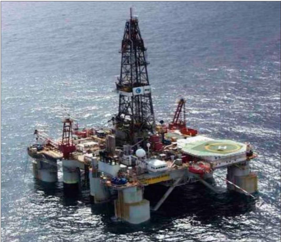
Figure I-1-2. A deep ballasted semi-submersible mobile offshore drilling unit
1.2.3 Mobile offshore drilling units: self-elevating unit (jack-up)
A jack-up rig, or a self-elevating unit, is a mobile platform that consists of a buoyant hull fitted with a number of moveable legs (typically three or four). These rigs are towed to and from locations or may be self-propelled. When on site the legs (which can measure 137 m (450 ft) or more) are ‘jacked’ down until they penetrate the seabed or sit on the sea floor, with the main body of the rig about 15.24 m (50 ft) above sea level. The height of the legs when on station is dependent upon the depth of the water. When on tow, the legs are jacked up and specific limitations are applied for helicopter operations to moving decks (Part 1, Chapter 8, 8.3 refers). When in the jacked-down position, helidecks are not subject to significant movement and therefore behave more like fixed platforms. Jack-up rigs are classified as MODUs and should therefore comply with standards for helidecks, also addressed in the IMO MODU Code.
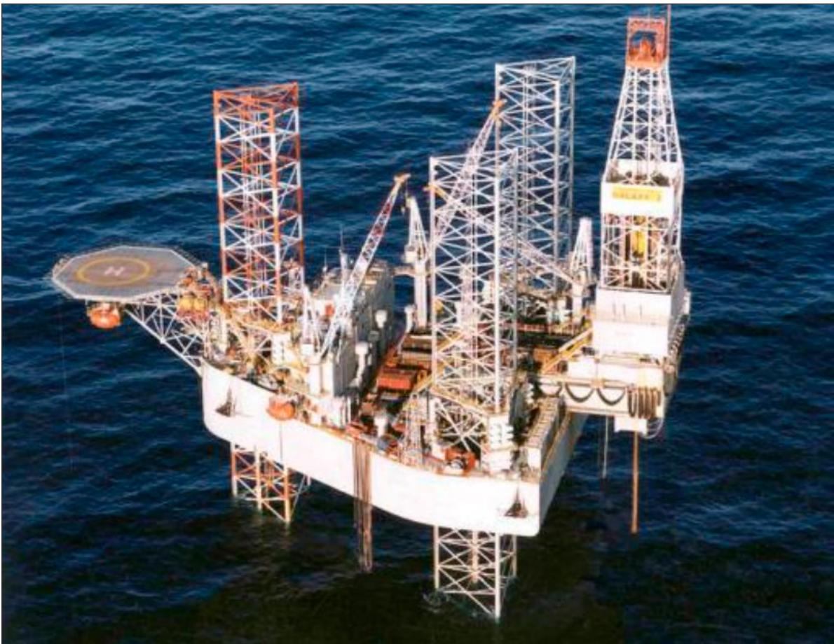
Figure I-1-3. A three-legged jacked-up mobile offshore drilling unit
1.2.4 Floating production storage and offloading (FPSO) and tankers
An FPSO unit is a floating vessel used for the production and processing of hydrocarbons and for the storage of oil, until the oil can be offloaded onto a tanker (Figure I-1-4 refers)) or, less frequently, transported through a pipeline. The FPSO extracts and stores the oil while the tanker hooks up to the FPSO before it shuttles the oil ashore. FPSOs are either purpose-built or can be made from the conversion of an oil tanker. They are very effective when used in remote or deep-water locations, where seabed pipelines are not a commercially viable option. Other forms of FPSO may include a floating storage and offloading unit (FSO) or a liquefied natural gas (LNG) floating storage and regasification unit.
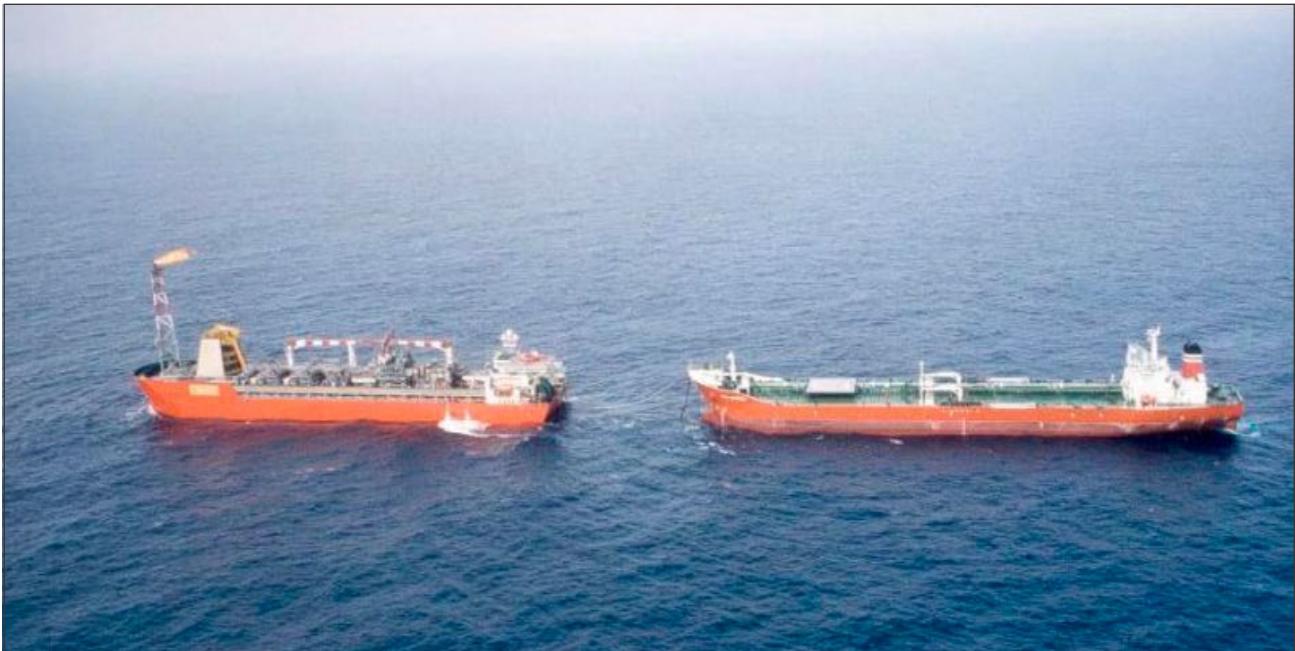
Figure I-1-4. Tanker (right) hooks up with a FPSO (left)
1.3 SHIPBOARD HELIPORTS
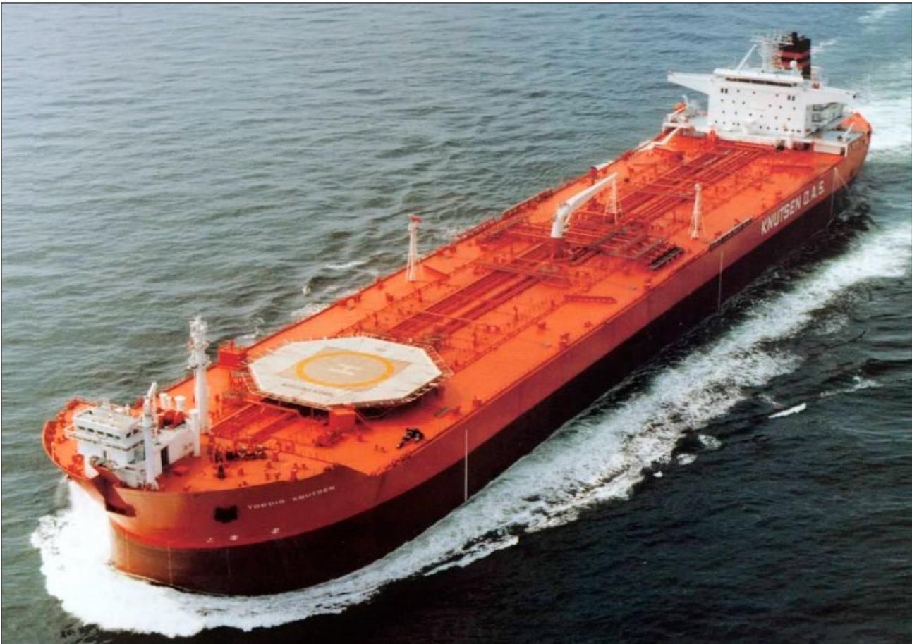
Figure I-1-5. A tanker with a purpose-built mid-ship centreline shipboard heliport
1.3.1 Drill ships
Drill ships are merchant vessels designed for use in exploratory offshore drilling for new oil and gas wells. They can be either purpose-built or converted older vessels, and are kept on station by standard anchoring systems or by a dynamic positioning system (DPS). In recent years they have increasingly been used to drill in deep water or in ultra-deep water and, in this operating environment, require the most advanced DPS.
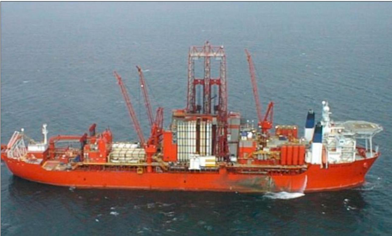
Figure I-1-6. A high-mounted bow helideck on a drill ship
1.3.2 Small vessels
Support and survey vessels are among the most challenging ships to fly to, especially at night. Vessels can be quite small and the helideck can be high above the bow, over the stern or even amidships.
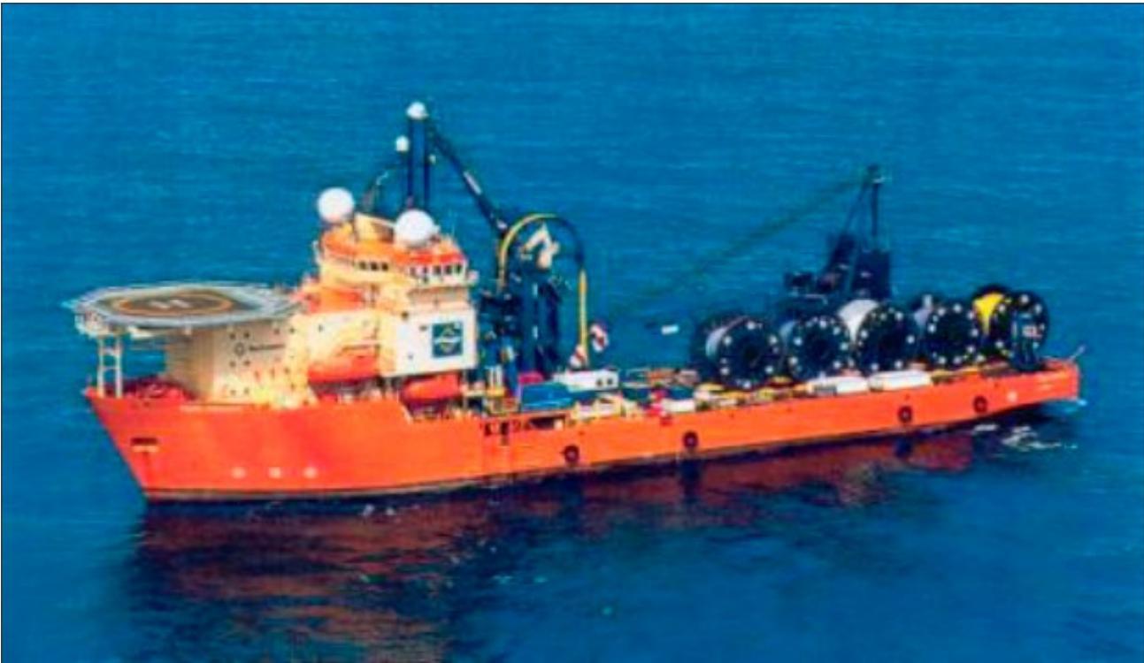
Figure I-1-7. A high bow mounted helideck on a pipe laying vessel
1.3.3 Non-purpose-built landing area on ship’s side — tanker port and starboard
Some helicopter landing areas, located on tankers, consist of non-purpose-built ship side arrangements, located on either side of the vessel. For non-purpose-built facilities, the control of ground-based, and usually immovable, obstacles become an issue. In this case, care needs to be taken to ensure that deck-mounted obstacles, which may form part of the vessel superstructure, do not impinge on the safety of helicopter operations. This is discussed in detail in Chapter 4, 4.6.
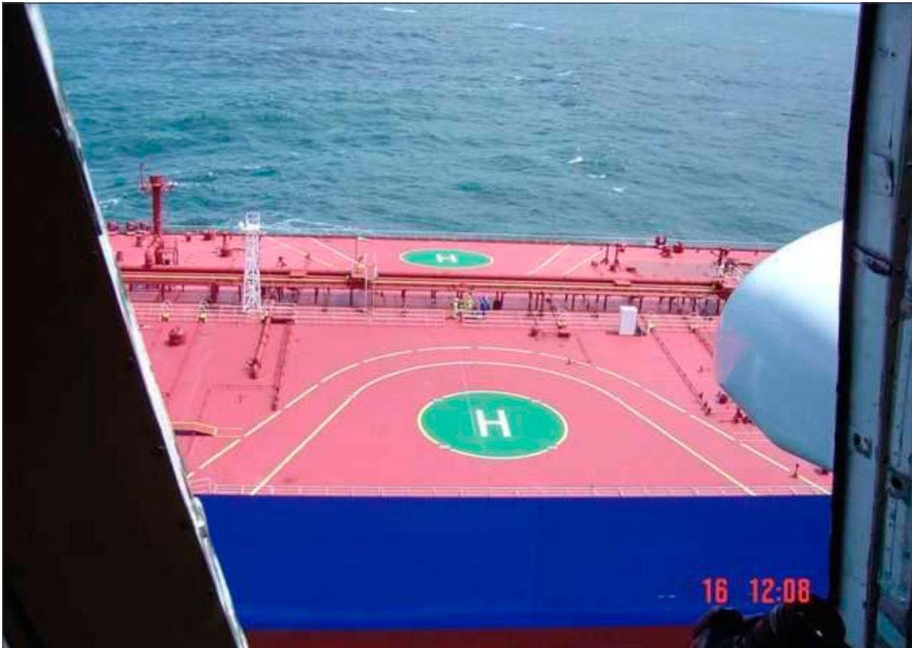
Figure I-1-8. Non-purpose-built ship side landing areas (port and starboard)
1.4 TABLE OF CHARACTERISTICS FOR COMMON OFFSHORE HELICOPTER TYPES
Table I-1-1. D-value, “t” value and other helicopter type criteria (metric units)
| Type | D-value(metres) | Perimeter'D'marking | Rotor diameter(metres) | Max weight(kg) | 4value |
| EC130 | 12.60 | 13 | 10.70 | 2432 | 2.4t |
| MD902 | 11.84 | 12 | 10.31 | 2835 | 2.8t |
| Bell 206B | 11.95 | 12 | 9.51 | 1452 | 1.5t |
| Bo105D | 12.00 | 12 | 9.90 | 2400 | 2.4t |
| EC135 T2+ | 12.20 | 12 | 10.20 | 2910 | 2.9t |
| Bell 407 | 12.70 | 13 | 10.40 | 2381 | 2.4t |
| Bell 429 | 13.00 | 13 | 11.00 | 3402 | 3.4t |
| Bell 206L IV | 12.96 | 13 | 10.44 | 2018 | 2.0 t |
| AS355 | 12.94 | 13 | 10.69 | 2600 | 2.6t |
| BK117 | 13.00 | 13 | 11.00 | 3200 | 3.2t |
| Bell 427 | 13.00 | 13 | 11.28 | 2971 | 3.0t |
| A109 | 13.05 | 13 | 11.00 | 2600 | 2.6t |
| AW119 | 13.02 | 13 | 10.83 | 2720 | 2.7t |
| EC145/H145 | 13.03 | 13 | 11.00 | 3585 | 3.6t |
| AS365 N2 | 13.68 | 14 | 11.93 | 4250 | 4.3t |
| AW189 | 17.60 | 18 | 14.60 | 8300 | 8.3t |
| EC175/H175 | 18.06 | 18 | 14.80 | 7500 | 7.5t |
| AS365 N3 | 13.73 | 14 | 11.94 | 4300 | 4.3t |
| EC155 B1 | 14.30 | 14 | 12.60 | 4850 | 4.9t |
| Bell 222 | 15.33 | 15 | 14.08 | 3742 | 3.7t |
| Bell 430 | 15.29 | 15 | 12.80 | 4218 | 4.2t |
| Ka-32 | 15.90 | 16 | 15.90 | 12600 | 12.6t |
| S76 | 16.00 | 16 | 13.40 | 5307 | 5.3t |
Part I. Offshore heliports Chapter 1. General
| Type | D-value(metres) | Perimeter $\mathcal { D } '$ marking | Rotor diameter(metres) | Max weight(kg) | $t '$ value |
| AW139 | 16.63 | 17 | 13.80 | 6 800 | 6.8t |
| Bell 412EP | 17.13 | 17 | 14.02 | 5398 | 5.4t |
| Bell 212 | 17.46 | 17 | 14.00 | 5080 | 5.1t |
| AS332L | 18.70 | 19 | 15.60 | 8599 | 8.6t |
| AS332 L2 | 19.50 | 20 | 16.20 | 9 300 | 9.3t |
| EC225 | 19.50 | 20 | 16.20 | 11000 | 11.0t |
| S92A | 20.88 | 21 | 17.17 | 12565 | 12.6 t |
| Mil Mi-17 | 25.30 | 25 | 21.10 | 13 000 | 13.0t |
| Mil Mi-8 | 25.24 | 25 | 21.29 | 12 000 | 12.0t |
| S61N | 22.20 | 22 | 18.90 | 9 298 | 9.3t |
| AW101 | 22.80 | 23 | 18.60 | 15 600 | 15.6t |
Note.— The specifications presented in this table should be verified against manufacturer derived data
Note.— Specifications presented in this table should be verified against manufacturer derived data.
Table I-1-2. D-value, “t” value and other helicopter type criteria (imperial units)
| Type | D-value(feet) | Perimeter $\mathcal { D } '$ marking | Rotor diameter(feet) | MaxWeight(1bs) | Maximumallowablemassmarking |
| EC130 | 35.00 | 35 | 35.10 | 5361 | 5.4 |
| MD902 | 38.80 | 39 | 33.80 | 6 250 | 6.3 |
| Bell 206B | 39.20 | 39 | 33.00 | 3201 | 3.2 |
| Bo105D | 39.36 | 39 | 32.48 | 5291 | 5.3 |
| EC135 T2+ | 40.00 | 40 | 33.50 | 6400 | 6.4 |
| Bell 407 | 41.40 | 41 | 35.00 | 5250 | 5.3 |
| Bell 429 | 41.75 | 42 | 36.00 | 7500 | 7.5 |
| Bell 206L | 42.40 | 42 | 37.00 | 4450 | 4.5 |
| AS355 | 42.50 | 43 | 35.00 | 5732 | 5.7 |
| BK117 | 42.65 | 43 | 36.00 | 7055 | 7.1 |
| Type | D-value(feet) | PerimeterD'marking | Rotor diameter(feet) | MaxWeight(1bs) | Maximumallowablemassmarking |
| Bell 427 | 42.65 | 43 | 37.00 | 6550 | 6.6 |
| A109 | 42.80 | 43 | 36.00 | 5732 | 5.7 |
| AW119 | 42.70 | 43 | 35.50 | 6000 | 6.0 |
| EC145 | 42.70 | 43 | 36.00 | 7900 | 7.9 |
| AS365 N2 | 44.80 | 45 | 39.10 | 9370 | 9.4 |
| EC175/H175 | 44.90 | 45 | 35.00 | 16 535 | 16.5 |
| AS365 N3 | 45.00 | 45 | 39.10 | 9480 | 9.5 |
| EC155 B1 | 46.90 | 47 | 41.30 | 10700 | 10.7 |
| Bell 22 | 49.50 | 50 | 40.00 | 8245 | 8.2 |
| Bell 430 | 50.10 | 50 | 42.00 | 9300 | 9.3 |
| Ka-32 | 52.02 | 52 | 52.02 | 27778 | 27.8 |
| S76 | 52.49 | 52 | 44.00 | 11700 | 11.7 |
| AW139 | 54.63 | 55 | 45.28 | 15000 | 15.0 |
| Bell412EP | 56.20 | 56 | 46.00 | 11900 | 11.9 |
| Bell 212 | 57.25 | 57 | 48.20 | 11200 | 11.2 |
| AW189 | 57.90 | 58 | 47.11 | 18300 | 18.3 |
| AS332L | 61.34 | 61 | 49.60 | 19000 | 19.0 |
| AS332 L2 | 63.94 | 64 | 53.20 | 20500 | 20.5 |
| EC225 | 63.96 | 64 | 53.20 | 24250 | 24.3 |
| S92A | 68.49 | 68 | 56.32 | 28000 | 28.0 |
| Mil Mi-17 | 83.00 | 83 | 69.03 | 28660 | 28.3 |
| Mil Mi-8 | 82.10 | 69 | 69.10 | 26455 | 26.5 |
| S61N | 72.80 | 73 | 62.00 | 20499 | 20.5 |
| AW101 | 74.80 | 75 | 61.00 | 34400 | 34.4 |
Part I. Offshore heliports Chapter 1. General
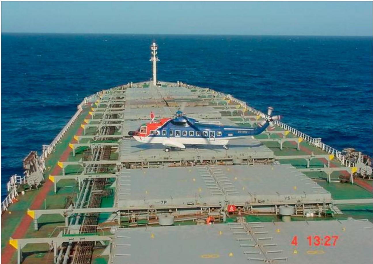
Figure I-1-9. An S61N helicopter lands on the hatch cover of a large vessel
Chapter 2
HELIPORT DATA
2.1 INTRODUCTION
2.1.1 For a fixed facility, the heliport elevation is measured at the highest point of the final approach and take-off area(s) (FATO(s)) and recorded on the helideck information plate (HIP) (Figure I-2-1 refers). Heliport elevation (in feet or metres) is the height of the FATO(s) above mean sea level (AMSL). For floating installations and vessels, the heliport elevation is measured from the keel of the installation/vessel to the highest point of the FATO. The profile information is independent from the draft marking and the actual elevation above the water level. The installation/vessel crew has to calculate the current height above the water level by subtracting the current draft at the perpendicular closest to the helideck and providing this to the helicopter operator.
Note.—The helicopter operator should include the corrected elevation information supplied by the installation/vessel operator in the helideck template.
2.1.2 A Helideck directory (HD) entry should promulgate additional information for the helicopter landing area including the D-value of the FATO, whether expressed in metric metres or in imperial feet and inches, and specify the maximum allowable mass of the helicopter permitted to operate to the FATO, a marking expressed either in metric tonnes (known as the t-value), or in imperial units (expressed in lbs). The D-value, in metres or feet, corresponds to the size (diameter) of the FATO (and where coincident, to the size (diameter) of the TLOF) while the maximum allowable mass is a t-value marking expressing metric tonnes or a marking defined by imperial units (lbs), that equates to the load-bearing strength of the touchdown and liftoff area (TLOF) (see Chapter 3, 3.1). Detailed guidance on how these marking issues should be displayed, whether expressed using metric or imperial units, is presented in Chapter 5, 5.3 and 5.4.
2.2 AUTHORIZATION OF OFFSHORE HELIPORTS — ASSESSMENT CHECKLIST, CONTENT OF A HELIDECK DIRECTORY (HD) AND CONTENT OF A HELIDECK INFORMATION PLATE (HIP)
2.2.1 General
2.2.1.1 The content of the operations manual relating to the specific usage of offshore helicopter landing areas (helidecks and shipboard heliports) should contain both the listing of limitations in an HD and a pictorial representation (template) of each offshore location and its helicopter landing area, recording all necessary permanent information. The HD should be amended as necessary and indicate the most recent status of each offshore helicopter landing area concerning non-compliance with applicable Standards, contained in Annex 14 — Aerodromes, Volume II — Heliports, with limitations, warnings, cautions or other comments of operational importance. An example of a typical template is shown in Figure I-2-1.
2.2.1.2 In order to ensure that the safety of flights is not compromised, the operator should obtain relevant information and details for a compilation of the HD, and the pictorial representation, from the owner/operator of the offshore helicopter landing area.
2.2.1.3 If more than one name for the offshore location exists, the common name painted of the surface of the landing area should be listed, but other recent names should also be included in the HD (e.g. radio call sign if different). After renaming an offshore location, the previous name should be retained in the HD for a period of six months following the change.
2.2.1.4 Any limitations associated with an offshore location should be included in the HD. With complex installation arrangements including combinations of installations/vessels (e.g. combined operations), a separate listing in the HD, accompanied by diagrams where necessary, may be required.
2.2.1.5 Each offshore helicopter landing area should be assessed based on its limitations, warnings, instructions and restrictions to ensure its safety. The following factors, as a minimum, should be considered:
a) the physical characteristics of the landing area, including size and load-bearing capability;
b) the preservation of obstacle-protected surfaces (the most basic safeguard for all flights), which include:
-
the minimum 210° obstacle-free sector (OFS);
-
the 150° limited obstacle surface (LOS); and
-
the minimum 180° falling ‘5:1’ gradient with respect to significant obstacles;
Note.— If these sectors/surfaces are infringed, even on a temporary basis and/or if an adjacent installation or vessel infringes the obstacle protected surfaces related to the landing area, an assessment should be made to determine whether it is necessary to impose operating limitations and/or restrictions to mitigate any non-compliance with the criteria.
c) marking and lighting:
- for operations at night:
i) adequate illumination of the perimeter of the landing area, utilizing perimeter lighting;
ii) adequate illumination of the location of the touchdown marking by use of a lit touchdown/positioning marking and lit heliport identification marking or by perimeter floodlighting;
-
presence of dominant obstacle paint schemes and lighting;
-
appropriate condition of helideck markings; and
-
adequacy of general installation and structure lighting;
Note.— Any limitations with respect to non-compliant lighting arrangements should be annotated as ‘daylight-only operations’ in the HD.
d) deck surface:
-
assessment of surface friction;
-
adequacy and condition of helideck net (where provided);
-
fit-for-purpose drainage system;
-
deck edge safety netting or shelving;
-
system of tie-down points adequate for the range of helicopters in use; and
-
cleanliness of the surface e.g. removal of bird guano, sea spray, snow and ice;
e) environment:
-
foreign object damage;
-
assessment of physical turbulence generators, e.g. structure-induced turbulence due to clad derrick;
-
bird control measures in place;
-
air quality degradation due to exhaust emissions, hot gas vents (turbulence and thermal effects) or cold gas vents; and
-
possible inclusion of adjacent offshore installations in air quality assessment;
Note.— To assess for potential adverse environmental effects described in 2), 4) and 5), an offshore location should be subject to appropriate studies e.g. wind tunnel testing, computational fluid dynamics (CFD) analysis.
f) rescue and firefighting:
-
fixed foam application systems (FFAS) for delivery of firefighting media to the landing area, e.g. deck integrated firefighting system (DIFFS);
-
delivery of primary media types, critical area, application rate and duration;
-
deliveries of complementary agent(s), media types, capacity and discharge;
-
personal protective equipment (PPE); and
-
rescue equipment and crash box/cabinet;
g) communications and navigation:
-
presence and/or quality of aeronautical radio(s);
-
radio-telephony (R/T) call sign to match offshore location name and side identification (should be simple and unique);
-
non-directional beacon (NDB) or equivalent (as appropriate); and
-
radio log;
h) fuelling facilities: in accordance with relevant national guidance and regulations;
i) additional operational and handling equipment:
-
windsock(s);
-
meteorological information including wind, pressure, air temperature and dew point temperature recording/ displaying mean wind (10 minute wind) and gusts;
-
deck motion recording and reporting (helideck motion system - HMS) where applicable;
-
passenger briefing system;
-
chocks;
-
tie-down strops/ropes;
-
weighing scales;
-
a suitable power source for starting helicopters (ground power unit (GPU)) where applicable; and
-
equipment for clearing the landing area of snow and ice and other contaminants;
j) personnel: qualified helicopter landing area staff (e.g. helicopter landing officer/helicopter deck assistant and firefighters, etc.) and persons required to assess local weather conditions or communicate with helicopter by radio-telephony.
2.2.1.6 For offshore locations for which there is incomplete information, ‘limited’ usage based on the information available may be considered by the operator, subject to a risk assessment prior to the first helicopter visit. During subsequent operations, and before any restriction on heliport usage is lifted, information should be gathered and the following should apply:
a) pictorial (static) representation:
-
template blanks (see Figure I-2-1) should be available to be filled in during flight preparation, on the basis of the information given by the offshore location owner/operator and flight crew observations;
-
where possible, suitably annotated photographs may be used until the HD and template have been completed;
-
until the HD and template have been completed, conservative operational restrictions (e.g. performance, routing, etc.) may be applied;
-
any previous inspection reports should be obtained and reviewed by the operator; and
-
an inspection of the offshore helicopter landing area should be carried out to verify the content of the completed HD and template. Once found suitable, the landing area may be considered authorized for use by the operator;
b) with reference to the above, the HD should contain at least the following:
-
HD revision date and number;
-
generic list of helideck motion limitations;
-
name of offshore location;
-
‘D’ value; and
-
limitations, warnings, instructions and restrictions;
Note.—The content of the helicopter landing area authorization or certificate should include 3), 4) and 5).
c) the template should contain at least the following fields (see Figure I-2-1):
-
name of the offshore location;
-
R/T call sign;
-
helicopter landing area identification marking;
-
side panel identification marking;
-
landing area elevation;
-
maximum installation/vessel height;
-
‘D’ value;
-
type of offshore location:
i) fixed: permanently attended installation (PAI);
ii) fixed: not permanently attended installation (NPAI);
iii) vessel type (e.g. diving support vessel, tanker);
iv) mobile offshore drilling unit: semi-submersible;
v) mobile offshore drilling unit: jack-up; and
vi) floating production storage offloading (FPSO);
-
name of the owner/operator;
-
geographical position, where appropriate;
-
communication and navigation (com/nav) frequencies and identification;
-
general drawing of the offshore location showing the helicopter landing area with annotations showing location of derrick, masts, cranes, flare stack, turbine and gas exhausts, side identification panels, windsock, etc.;
-
plan view drawing, chart orientation from the general drawing, to show the above. The plan view will also show the 210 degree sector orientation in degrees true;
-
type of fuelling:
i) pressure and gravity;
ii) pressure only;
iii) gravity only; and
iv) none;
-
type and nature of firefighting equipment;
-
availability of ground power unit (GPU);
-
deck heading;
-
maximum allowable mass (metric tonnes “t” value) or lbs; and
-
revision date of publication.
Part I. Offshore heliports Chapter 2. Heliport Data
| Installation/vessel name | R/T callsign:… | Helideck identification:… | ||
| Helideck elevation:...f. | Maximum height:..ft.. | Side identification:.… | ||
| Type of installation/vessel: | D-value:..m and/or ft | |||
| Position:2 | Operator3 | |||
| ATIS:VHF 123.456 | ||||
| COM | LOG: VHF123.456 | NAV | NDB: 123 (ident.) | |
| Traffic: VHF123.456 | GNSS: 123 | |||
| Deck: VHF123.456 | VOR/DME: 123 | |||
| Not applicable: | ||||
  | ||||
| Fuelling:. | GPU:.5 | Deck heading:… | ||
| MTOM:.. T and/or Ibs | Status light:.. | Firefighting equipment:7 | ||
| Revision date:… | ||||
Figure I-2-1. Helicopter landing area template
- Fixed permanently attended, fixed not permanently attended; vessel type (e.g. diving support vessel); MODU - semi-submersible; MODU - jack-up; FPSO, tanker.
2 Latitude and longitude in degrees, minutes and decimals of a minute.
3 Name of operator of the installation/vessel.
4 Pressure/gravity; pressure; gravity; no.
5 Yes; no; 28v DC.
6 Yes; no (as required by applicable codes e.g. IMO MODU Code).
Type of foam (e.g. 3 per cent aqueous film forming foams (AFFF) (3 per cent AFFF)) and nature of primary media delivery (e.g. DIFFS).
Chapter 3
PHYSICAL CHARACTERISTICS
3.1 HELIDECK AND PURPOSE-BUILT SHIPBOARD HELIPORT STRUCTURAL DESIGN
3.1.1 The helicopter landing area and any parking area provided (see Chapter 8, 8.1) should be of sufficient size and strength and laid out to accommodate the heaviest and largest helicopter requiring to use the facility (referred to as the design helicopter). The structure should incorporate a load-bearing area designed to resist dynamic loads without disproportionate consequences from the impact of an emergency landing anywhere within the area bounded by the touchdown and lift-off area (TLOF) perimeter markings. Consideration should be given to the possibility of accommodating an unserviceable helicopter in a parking area (where provided) adjacent to the helideck to allow a relief helicopter to land.
Note.— If this contingency is designed into the construction and operating philosophy of the installation or vessel, the helicopter operator should be advised of any mass restrictions imposed on a relief helicopter due to the presence of an unserviceable helicopter, whether elsewhere on the landing area or removed to a parking area, where provided.
3.1.2 The helicopter landing area and its supporting structure should be constructed from steel, aluminium alloy or other suitable materials designed and fabricated to applicable standards. Where differing materials are to be used in near contact, the detailing of the connections should be such as to avoid the incidence of galvanic corrosion.
3.1.3 Both the ultimate limit states (ULS) and the serviceability limit states (SLS) should be assessed. The structure should be designed for the SLS and ULS conditions appropriate to the structural component being considered as follows:
a) for deck plate and stiffeners:
-
ULS under all conditions; and
-
SLS for permanent deflection following an emergency landing;
b) for helicopter landing area supporting structure:
-
ULS under all conditions; and
-
SLS.
3.1.4 The supporting structure, deck plates and stringers should be designed to resist the effects of local wheel or skid actions acting in combination with other permanent, variable and environmental actions. Helicopters should be assumed to be located within the TLOF perimeter markings in such positions that maximize the internal forces in the component being considered. Deck plates and stiffeners should be designed to limit the permanent deflection (deformation) under helicopter emergency landing actions to no more than 2.5 per cent of the clear width of the plates between supports. Stiffener webs should be assessed locally under wheels or skids and at the support areas so as not to fail under landing gear actions due to emergency landings. Tubular structural components forming part of the supporting structure should be checked for vortex-induced vibrations due to wind.
Note.— For the purposes of the following sections it may be assumed that single main rotor helicopters will land on the wheel or wheels of two landing gear or on both skids where skid-fitted helicopters are in use. The resulting loads should be distributed between two main undercarriages. Where advantageous, a tire contact area may be assumed within the manufacturer’s specification.
3.1.5 Case A — Helicopter landing situation
A helideck or a purpose-built shipboard heliport should be designed to withstand all the forces likely to act when a helicopter lands. The load and load combinations to be considered should include:
a) Dynamic load due to impact landing.
This should cover both a heavy landing and an emergency landing. For the former an impact load of 1.5 x maximum (certificated) take-off mass (MTOM) of the design helicopter should be used, while for an emergency landing an impact load of 2.5 x MTOM should be applied in any position on the landing area together with the combined effects of b) to g) inclusive. Normally the emergency landing case will govern the design of the structure.
b) Sympathetic response of the landing platform.
After considering the design of the helideck structures, i.e. the supporting beams and columns, and the characteristics of the design helicopter, the dynamic load (see a) above) should be increased by a suitable structural response factor (SRF) to take account of the sympathetic response of the helicopter landing area structure. The factor to be applied for the design of the helicopter landing area framing depends on the natural frequency of the deck structure. Unless specific values are available based on particular undercarriage behaviour and deck frequency, a minimum SRF of 1.3 should be assumed.
c) Overall superimposed load on the landing platform.
To allow for any appendages that may be present on the deck surface, such as helideck nets or lighting, in addition to the wheel loads, an allowance of 0.5 kN/m2 should be applied over the whole area of the helideck.
d) Lateral load on landing platform supports.
The helicopter landing platform and its supports should be designed to resist concentrated horizontal imposed actions equivalent to 0.5 x MTOM of the design helicopter, distributed between the undercarriages in proportion to the applied vertical loading in the horizontal direction that will produce the most severe loading for the structural component being considered.
e) Dead load of structural members.
This is the normal gravity load on the element being considered.
f) Environmental actions on the helideck.
-
Wind actions on the helideck structure should be applied in the direction which, together with the horizontal impact actions, produces the most severe load case for the component considered. The wind speed to be considered should be that restricting normal (non-emergency) helicopter operations at the landing area. Any vertical up and down action on the helideck structure due to the passage of wind over and under the helideck should be considered.
-
Inertial actions due to platform motions – the effect of accelerations and dynamic amplification arising from the predicted motions of the fixed or floating platform in a storm condition with a ten-year return period should be considered.
g) Punching Shear.
Where helicopters with wheeled undercarriages are operated, a check should be made for the punching shear of a wheel of the landing gear with a contact area of 65 x 103 mm2 acting in any probable location. Particular attention to detailing should be taken at the junction of the supports and at the platform deck.
3.1.6 Case B — Helicopter at rest situation
In addition to Case A above, a helideck or a purpose-built shipboard heliport should be designed to withstand all the applied forces that could result from a helicopter at rest. As such, the following loads should be taken into account:
a) Imposed load from helicopter at rest.
All parts of the helideck or shipboard heliport should be assumed to be accessible to helicopters, including any separate parking area (see Chapter 8, 8.1) and should be designed to resist an imposed (static) load equal to the MTOM of the design helicopter. This load should be distributed between all the landing gear, and applied in any position so as to produce the most severe loading on each element considered.
b) Overall superimposed load.
To allow for personnel, freight, refuelling equipment and other traffic, snow and ice, and rotor downwash effects etc., a general area imposed action of 2.0 kN/m2 should be added to the whole area of the helideck or shipboard heliport.
c) Horizontal actions from a tied-down helicopter including wind actions.
Each tie-down should be designed to resist the calculated proportion of the total wind action on the design helicopter imposed by a storm wind with a minimum one-year return period.
d) Dead load.
This is the normal gravity load on the element being considered and should be regarded to act simultaneously in combination with a) and b). Consideration should also be given to the additional wind loading from any parked or secured helicopter (see also e) 1) below).
e) Environmental actions.
1) Wind loading.
Wind loading should be allowed for in the design of the platform. The one-hundred-year return period wind actions on the helicopter landing area structure should be applied in the direction that, together with the imposed lateral loading, produces the most severe load condition on each structural element being considered.
- Acceleration forces and other dynamic amplification forces.
For the effects of these forces arising from the predicted motions of mobile installations or vessels, the appropriate environmental conditions corresponding to a ten-year return period should be considered.
Note.— Not all helicopter landing areas on ships consist of purpose-built structures. Some helicopter landing areas may alternatively utilize areas of the ship’s deck which were not specifically designed for helicopter operations, e.g. main decking on a ship’s side, a large hatch cover, etc. In the case of a non-purpose-built structure it should be established, before authorizing a landing area, that the area selected can withstand the dynamic and static loads imposed for the types of helicopters for which it is intended.
3.2 HELIDECK/SHIPBOARD HELIPORT DESIGN CONSIDERATIONS — INCLUDING ENVIRONMENTAL EFFECTS
Note.— In the following sections, the term “helideck” is used throughout to denote a heliport on a fixed or floating facility such as an exploration and/or production unit used for the exploitation of oil and gas. Where heliports are located on ships, it would be for the designer to assess whether each aspect of design is appropriate for the “shipboard heliport” under consideration. A stand-alone section (Section 3.2.5 refers) is provided to address special considerations for floating facilities and ships and has particular applicability to all shipboard heliports as well as to helidecks located on floating offshore facilities.
3.2.1 General design considerations
3.2.1.1 The location of a helideck is often a compromise between the conflicting demands of the basic design requirements, the space limitations on the often cramped topsides of offshore facilities, and the need for the facility to provide for a variety of functions. It is almost inevitable that helidecks installed on the cramped topsides of offshore structures will suffer to some degree from their proximity to tall and bulky structures, and to gas turbine exhausts or flares. The objective for designers becomes to create topside designs incorporating helidecks that are safe and ‘friendly’ to helicopter operations by minimizing adverse environmental effects (mainly aerodynamic, thermal and wave motion) that can affect helicopter operability.
Note.— Where statutory design parameters cannot be fully met, it may be necessary for restrictions or limitations to be imposed upon helicopter operations which could, in severe cases, lead to a loss of payload when the wind is blowing through a turbulent sector.
3.2.1.2 Helidecks are basically flat plates and are therefore relatively streamlined structures. In isolation, they would present little disturbance to the wind flow, and helicopters would be able to operate safely to them in a more or less undisturbed airflow environment. Difficulties may arise, however, when the wind has to deviate around the bulk of the offshore installation, causing large areas of flow distortion and turbulent wakes and/or because the producing facility itself is a source of hot or cold gas emissions. The effects fall into three main categories:
-
the flow around the bulk of the offshore facility. Platforms in particular are slab-sided, non-streamlined assemblies (bluff bodies) that create regions of highly distorted and disturbed airflow in the vicinity;
-
the flow around large items of superstructure such as cranes, drilling derricks and exhaust stacks generates turbulence that can affect helicopter operations (see Section 3.2.2). Like the platform itself, these are bluff bodies which encourage turbulent wake flows to form behind the bodies; and
-
hot gas flows emanating from exhaust outlets and flare systems (see Section 3.2.3) and/or cold flaring (see Section 3.2.4).
3.2.1.3 A helideck on a fixed or floating offshore facility should ideally be located at or above the highest point of the main structure. This will minimize the occurrence of turbulence downwind of adjacent structures. However, while this is desirable, in many parts of the world, for a helideck much in excess of 60 m above sea level, the regularity of helicopter operations may be impacted by low cloud base conditions. Conversely, low elevation helidecks may also adversely affect helicopter operations where one-engine inoperative (dropdown) performance is an operational requirement for a State, i.e. due to the insufficient dropdown between the landing area and the sea surface. Consequently, a trade-off may be required between the height of the helideck above surrounding structures and its absolute height above mean sea level (AMSL).
3.2.1.4 A key driver for the location of the helideck is the need to provide a generous sector, clear of physical obstructions for approaching/departing helicopters and also sufficient vertical clearance for multi-engine helicopters to lose altitude after take-off in the event of an engine failure. This will entail a design incorporating a minimum 210-degree obstacle-free sector with a falling gradient below the landing area over at least 180 degrees of this arc (these issues are discussed further in Chapter 4). Aerodynamically, the helideck should be as far away as possible from the disturbed wind flow around the platform. and in order to achieve this, in addition to providing the requisite obstruction-free areas described above, it is recommended that the helideck be located on the corner of the facility with as large an overhang as possible.
3.2.1.5 In combination with locating the helideck at an appropriate elevation and providing a vital air gap (see Section 3.2.1.8), the overhang will encourage the disturbed airflow to pass under the helideck, leaving a relatively clean ‘horizontal’ airflow above the deck. It is recommended that the overhang should be such that the centre of the helideck is vertically above or outboard of the corner of the facility’s superstructure.
3.2.1.6 When determining which corner of the facility the helideck should overhang, a number of considerations should be evaluated. The helideck location should:
a) facilitate a direct approach whenever possible;
b) provide for a clear overshoot;
c) minimize the need for sideways or backwards manoeuvring;
d) minimize the environmental impact due to turbulence, thermal effects etc.; and
e) allow, wherever possible, an approach to be conducted by the commander of the helicopter.
3.2.1.7 The relative weighting of these considerations will change depending on factors such as wind speed. However, the helideck should generally be located such that winds from prevailing directions carry turbulent wakes and exhaust plumes away from the helicopter approach path. To assess if this is likely to be the case, for fixed facilities, it will usually be necessary for designers to overlay the prevailing wind direction sectors over the centre of the helideck to establish prevailing wind directions, wind speed combinations and to assess the likely impact on helicopter operations for a helideck if sited at a particular location.
3.2.1.8 The height of the helideck AMSL and the presence of an air gap between the helicopter landing area and a supporting module are the most important factors in determining wind flow characteristics in the helideck environment. In combination with an appropriate overhang, an air gap separating the helideck from superstructure beneath it will promote beneficial wind flow over the landing area. If no air gap is provided, then wind conditions immediately above the landing area are likely to be severe, particularly if mounted on top of a large multi-storey accommodation block — it is the distortion of the wind flow that is the cause. However, allowing for an air gap, typically between 3 m and 6 m in height, has the effect of ‘smoothing out’ distortions in the airflow immediately above the helideck. Helidecks mounted on very tall accommodation blocks will require the largest clearance (typically 5 to 6 m) while those on smaller blocks, and with a very large overhang, will tend to require smaller clearances (typically 3 to 4 m). For shallow superstructures of three storeys or less, such as are often found on semi-submersible drilling facilities, a 1 m air gap may be sufficient; but there is scope to increase the air gap as long as the size and presence of a more generous air gap does not have an adverse effect on the stability of a floating facility or the sea-keeping qualities of a ship.
Note.— To avoid wave loading on the helideck, the air gap required by Section 3.2.1.8 is also provided to clear the maximum wave height that might be encountered during transportation and for operational conditions. For a shipboard heliport mounted on the deck of a floating vessel, the maximum vertical displacement due to vessel motion should also be taken into account.
3.2.1.9 It is important that the air gap is preserved throughout the operational life of the facility, and care is taken to ensure that the gap between the underside of the helideck structure and the superstructure beneath does not become a storage area for bulky items that might hinder the free flow of air through the gap.
3.2.1.10 Where it is likely that necessary limitations and/or restrictions caused by issues that cannot easily be ‘designed out’ would have a significant effect on helideck operability, an option may exist for providing a second helideck which could be made available when the wind is blowing through the restricted sector of the primary helideck.
3.2.2 Effects of structure-induced turbulence
3.2.2.1 It is almost inevitable that helidecks installed on cramped topsides of offshore structures will suffer to some degree from their proximity to tall and bulky structures such as drilling derricks, flare towers, cranes or gas turbine exhaust stacks; it is often impractical to site the helideck above every tall structure. Any tall structure above and/or in the vicinity of the helideck may generate areas of turbulence or sheared flow downwind of the obstruction and therefore potentially pose a hazard to the helicopter. The severity of the disturbance will be greater, the bluffer the shape, and the broader the obstruction to the flow. The effect reduces with increasing distance downwind from the source of turbulence.
3.2.2.2 An assessment of the optimum helideck position should also take into account the location and configuration of drilling derricks, which can vary in relative location during the field life. A fully clad derrick, being a tall and solid structure, may generate significant wake downwind of the obstacle. Since the flow properties of the wake will be unstable, if the helideck is located downwind of a clad derrick, it is likely to be subject to large and random variations in wind speed and direction. As a guide on wake decay from bluff bodies, it should be assumed that the wake effects will not fully decay for a downwind distance of some ten to twenty structure widths (for a 10 m (33 ft) wide clad derrick this corresponds to a decay distance of between 100 to 200 m). Consequently, it is preferable that a helideck is not placed closer than ten structure widths from a clad derrick. However, few offshore facilities will be large enough to facilitate such clearances in their design, and any specification for a clad derrick has potential to result in operational limitations being applied when the derrick is upwind of the helideck. In contrast, unclad derricks are relatively porous, and while a wake still exists, it will be of a much higher frequency and smaller scale due to the flow being broken up by the lattice element of the structure. Consequently, a helideck can be safely located closer to an unclad derrick than to its clad equivalent. Generally, separations of at least five derrick widths at helideck height should be the design objective. Separations of significantly less than five structure widths may lead to the imposition of operating restrictions in certain wind conditions.
3.2.2.3 Gas turbine and other exhausts, whether or not in operation, may present a further source of structure-induced turbulence by forming a physical blockage to the air flow over the helideck and creating a turbulent wake (as well as presenting a potential hazard due to the hot exhaust). As a rule of thumb, to mitigate physical turbulence effects at the helideck, it is recommended that a minimum of ten structure widths be established between the obstruction and the helideck.
3.2.2.4 Other potential sources of turbulence which could give rise to turbulence effects may be present on offshore facilities, for example: large structures in close proximity to the helideck or a lay-down area in the vicinity of the helideck. In the latter case, the presence of bulky or tall items placed temporarily in lay-down areas close to the helideck could present a source of turbulence, and may increase hazards, as pilots otherwise familiar with a particular facility would not expect turbulence caused by a temporary obstruction. Ideally, a platform design should seek to ensure that any proposed lay-down areas are significantly below helideck level and/or are sufficiently remote from the helideck so as not to present a problem for helicopter operations.
3.2.3 Temperature rise due to hot exhausts
3.2.3.1 Increases in ambient temperature at the helideck are a potential hazard to helicopters, as increased temperatures result in less rotor lift and less engine power margin. Rapid temperature changes are a significant hazard, as the rate of change of temperature in the plume has potential to cause engine compressor surge or stall (often associated with an audible ‘pop’), which can result in loss of engine power, damage to engines and/or helicopter components and, ultimately, engine flame-out. It is therefore extremely important that helicopters avoid these conditions by ensuring that occurrences of higher than ambient conditions are foreseen, mapped, and, where necessary, that steps are taken to reduce payload to maintain an appropriate performance margin.
3.2.3.2 Gas turbine power generation systems are often a significant source of hot exhaust gases on fixed offshore facilities, while diesel propulsion or auxiliary power system exhausts occurring on some floating offshore facilities may also need to be considered. For certain wind directions the hot gas plumes from the exhausts will be carried by the wind directly across the helideck. The hot gas plume then mixes with the ambient air to increase the size of the plume, at the same time reducing its temperature by dilution.
3.2.3.3 Appropriate modelling designed to evaluate likely temperature rise would indicate that for gas turbine exhausts, with not untypical release temperatures up to 500°C and flow rates of between 50-100 kg/s, the minimum range at which the temperature rise in the plume drops to 2°C above ambient temperature would be in the range of 130-190m downwind of the source. Even where gas turbine generation systems incorporate waste heat recovery systems, resulting in lower gas temperatures of about 250°C, with the same flow rate assumptions the minimum distance before the temperature rise in the plume drops to 2°C above ambient is still in the range of 90-130 m downwind of the source.
3.2.3.4 In consideration of the above, except for the very largest offshore facilities, it is implied that regardless of design, there will always be a wind condition where temperature rise above the helideck exceeds the 2°C threshold. Consequently, it may be impossible to design a helideck that is compliant with these criteria for all conditions. The design aim then becomes one of minimizing the occurrence of high temperatures over the helideck rather than necessarily eliminating them completely. This can be achieved by ensuring that the facility layout and alignment directions are such that these conditions are only experienced rarely.
3.2.3.5 If it is necessary to locate power generation modules and exhausts close to the helideck, the location can still be acceptable provided that the stacks are high enough to direct the exhaust gas plume clear of arriving/departing helicopters. It is also important to ensure that the design of the stacks does not compromise helideck obstacle protection surfaces or that the stacks are not so wide as to present a source of structure-induced turbulence.
3.2.3.6 The helideck should be located so that winds from the prevailing wind direction(s) carry the plume away from the helicopter approach/departure paths. To minimize the effects of other wind directions, the exhausts should be sufficiently high to ensure that the plumes are above all the likely helicopter approach/departure paths. To achieve this, it is recommended that exhaust outlets are no less than 20 to 30 m above the helideck. The provision of downward-facing exhausts that initially direct hot exhaust gases towards the sea should be avoided, as experience has shown that hot plumes can rise from the sea surface and disperse in an unpredictable way, particularly in light and variable wind conditions.
3.2.3.7 In situations where it is difficult or impractical to reduce the potential interaction between the helicopter and the turbine exhaust plume to a sufficiently low level, consideration should be given to installing a gas turbine exhaust plume visualization system on facilities having a significant gas turbine exhaust plume problem, in order to highlight the hazard to pilots when operating by day, to minimize the potential effect of the plume by making it easier to see and avoid a plume encounter.
3.2.3.8 Helicopter performance may also be significantly impaired as a result of the combined radiated and convection heat effects from flare plumes under certain wind conditions. In moderate or strong winds, the radiated heat from a lit flare is rapidly dissipated and usually presents little problem for the helicopter, provided flight through the flare plume is avoided. However, in calm or light wind conditions, potential changes in air temperature in the vicinity of the helideck could be much greater and have a marked effect on the performance of the helicopter. Therefore, designers should exercise great care in determining the location and elevation of flare towers in relation to helicopter operations.
3.2.4 Cold flaring and rapid blow-down systems
3.2.4.1 Hydrocarbon gas can be released as a result of the production process of installation or from drilling facilities at various times. It is important to ensure that a helicopter does not fly into a cloud of hydrocarbon gas because even relatively low levels of concentration (typically above 10 per cent lower flammable limit (LFL)) can cause a helicopter engine to surge or flame-out with a consequent risk to the helicopter. Also, in these conditions, the helicopter poses a risk to the offshore facility because it is a potential ignition source for any hydrocarbon gas that may be present in the atmosphere. It must therefore be ensured that gas release points are as remote as possible from the helideck and from the helicopter flight path and that, in the event of any unforeseen gas release occurring during helicopter operations, the helicopter pilot is given sufficient warning so that, if necessary, the approach to the helideck can be broken off. Planned gas releases should only occur when helicopters are not in the area.
3.2.4.2 The blow-down system on a production facility depressurizes the process system releasing hydrocarbon gas. It will normally be designed to reduce the pressure to half its operating value in about fifteen minutes. However, for a large facility, this could feasibly require the release of fifty tonnes of gas, or more. Once down to the target pressure, in fifteen minutes or less, the remainder of the gas will continue to be released from the system. A blow-down may be automatically triggered by the detection of a dangerous condition in the process, or alternatively, manually triggered.
3.2.4.3 The blow-down system should have venting points that are as remote as possible from the helideck, and prevailing winds should be downwind of the helideck. It is not uncommon to have this vent on the flare boom, normally a good location. However, dilution of the gas to acceptably low levels of concentration (to <10 per cent LFL) may not occur until the plume is a considerable distance from the venting point. This distance may be anywhere between 200 m and 500 m depending on the size of the vent, the rate of venting and the prevailing wind speed.
3.2.4.4 Drilling facilities often have ‘poor-boy degassers’ which are used to release gas while circulating a well, but, except for a sudden major crisis such as a blow-out on a drilling facility, they are unlikely to release significant quantities of gas without warning. As with production facilities, it is not likely to be possible to locate the helideck sufficiently distant from the potential source of gas to always guarantee low levels of concentration at the helideck or in the helicopter flight path. The drilling facility may therefore need to curtail helicopter flights when well circulation activity is going on, or when problems are experienced down the well.
3.2.5 Special considerations for floating facilities and ships
Note.— Operating limits for safely remaining on the deck for a period necessary to affect safe passenger and cargo transfer are not considered in detail in Part I. See Chapter 8, 8.3 for deck motions reporting and recording.
3.2.5.1 As well as experiencing the aerodynamic effects and potential hazards highlighted above, floating installations and ships experience dynamic motions due to ocean waves. These motions are a potential hazard to helicopter operations, and motion limits will need to be established in order to maintain safe landing conditions. The recording and reporting of deck motions for the safe landing of helicopters is discussed in more detail in Chapter 8, 8.3.
3.2.5.2 The setting of helideck performance or motion limitations due to floating installations and ship dynamic motions is usually the responsibility of the helicopter operator and will be influenced by the type of floating facility or ship to which they are operating, the types of helicopters being operated, the operating conditions (e.g. whether day or night) and the location of the helideck (a helicopter operator may, for example, discuss landing limits with the Ship’s Master). Limitations typically apply to both vertical linear motions in heave and to angular motions expressed as pitch and roll. Some operators may consider additional parameters such as helideck inclination.
3.2.5.3 The angle of pitch and roll is the same for all points on a facility or ship but the amount of heave, sway or surge motion experienced will vary considerably depending on the precise location of the helideck. The severity of helideck motions will depend on:
a) the wave environment;
b) the size of the floating facility or ship (a smaller facility/ship generally tends to exhibit larger and faster wave induced motions than a large facility/ship where the response amplitude operator (RAO) is lower);
c) the characteristics of the floating facility or ship (certain hull forms exhibit larger wave induced motions than others, or are sensitive to particular sea conditions);
d) whether the floating facility or ship is moored, underway or under tow; and
e) the location of the heliport on a ship (vertical motions tend to be greater at the bow or stern of a ship than at the amidships location, and sway motions due to roll tend to increase with helideck height).
3.2.5.4 Sea states are usually characterized in terms of a significant wave height, an associated wave period and a wave energy spectrum. The motions of a ship or floating facility generally become larger as the significant wave height and period increase, but can be especially severe at certain wave periods (e.g. at natural roll or pitch periods) and may be sensitive to the range in frequency content of the wave spectrum experienced. The motion characteristics of a floating facility or ship may be reliably predicted by recourse to well-established computer models or to physical model testing. Helideck downtime will occur whenever the motions of the floating facility or ship exceed the derived criteria.
3.2.5.5 The operability of a helicopter landing area depends on its location on a floating facility or ship, both longitudinally and transversely. For ships and ship-shaped floating facilities, such as floating production storage and offloading (FPSOs) units, the pitching motion is such that the vertical heave motion experienced at the helideck on the bow or stern will generally be much greater than if the helideck is located amidships. Bow mounted helidecks can be particularly vulnerable to damage from green seas spilling over the superstructure of the ship, unless mounted high above deck level. Helidecks located off the vessel centreline, and cantilevered over the side (which usually provides the benefit of an unobstructed falling gradient over at least 180 degrees) may experience downtime due to heave motions caused by roll; although generally downtime for a helideck located amidships will be less than for a helideck located at the bow or stern of a ship or ship-shaped facility.
Note 1.— The location of the helideck, particularly on drilling facilities, is generally determined by factors other than the need to minimize heave motions, and it may be that the central area of an FPSO or drillship, for example, is otherwise occupied by processing or drilling equipment. A helideck located at the bow or stern may be more accessible to the temporary refuge and/or accommodation on board the facility which is another factor to consider, particularly where the helideck is designated to be a primary means of escape in the event of an incident occurring.
Note 2.— Some thruster-assisted FPSOs and dynamically positioned facilities or ships have the ability to turn to a desired heading which can be used operationally to minimize helideck downtime due to wave motions and aerodynamic effects. Where dynamic positioning (DP) systems are used to maintain heading control, it is important to ensure that the heading control system has adequate integrity (operability and redundancy) to maintain heading control at all times during helicopter operations.
3.2.6 Helideck design — environmental criteria
3.2.6.1 The design criteria may be applied to new fixed or floating facilities or ships and to significant modifications to existing facilities or ships and/or where operational experience has highlighted potential issues. When considering the volume of airspace to which the following criteria apply, designers should consider the airspace up to a height above helideck level which takes into consideration the requirement to accommodate helicopter landing and take-off decision points (or committal point). This is considered to be a height above the helideck corresponding to 9.14 m (30 ft) plus wheels-to-rotor height plus one rotor diameter. For the Sikorsky S92, for example, this equates to a column of air approximately 31 m (or 102 ft) above helideck surface level. The formula is clearly type-specific, being predicated on two of the dimensional aspects of the design helicopter, which are specific to type.
3.2.6.2 Generally, with respect to turbulence, a limit on the standard deviation of the vertical airflow velocity of 1.75 m/s should not be exceeded. However, note that this criterion is close to onshore background turbulence levels and that it would be unusual for a helideck not to exceed this lower threshold limit for at least some wind speeds and directions. In consideration of this, the lower threshold limit of 1.75 m/s is intended to draw attention to conditions that might result in operating difficulties and to alert pilots to exercise caution, unless or until operating experience has confirmed the airflow characteristics to be acceptable. Where these criteria are significantly exceeded (i.e. where the limit exceeds 2.4 m/s), there is the possibility that operational restrictions will be necessary and in this case it may be advisable to consider modifications to the helideck to improve the airflow (such as by increasing the air gap). Fixed or floating facilities or ships where there is a likelihood of exceeding the criteria should be subjected to appropriate testing e.g. a scale model in a wind tunnel or by computational fluid dynamics (CFD) analysis, to establish the wind environment in which helicopters will be expected to operate.
3.2.6.3 Unless there are no significant heat sources on the facility or ship, designers should commission a survey of ambient temperature rise based on a Gaussian dispersion model and supported by wind tunnel testing or CFD analysis. Where the results of such modelling and/or testing indicate there may be a rise of air temperature of more than 2°C averaged over a three second time interval, there is the possibility that operational limitations and/or restrictions may need to be applied.
3.2.6.4 For permanent multiple platform configurations, normally consisting of two or more bridge-linked modules in close proximity to each other, the environmental effects of hazards emanating from all constituent modules should be considered on helideck operations. This is particularly appropriate for the case of hot or cold gas exhausts where there will always be a wind direction which carries any exhaust plumes from a bridge-linked module in the direction of the helideck.
3.2.6.5 For temporary combined operations where typically one or more mobile facilities and/or ships are operated in close proximity to another (usually fixed) facility, the environmental effects emanating from one facility or ship should be fully considered for all facilities located together in temporary combined operations.
3.3 GUIDANCE ON HELIDECK SIZE AND SURFACE MOUNTED OBJECTS
Note.— In respect to D and D-value referenced in the following sections (Sections 3.3 and 3.4), it should be noted that this corresponds to the largest overall dimension of a single main rotor helicopter when rotors are turning, being measured, and expressed in metres, or in feet, from the most forward position of the main rotor tip path plane to the most rearward position of the tail rotor tip path plane or the helicopter structure.
3.3.1 For a helideck which is 1 D or greater, it is presumed that the final approach and take-off area (FATO) and the TLOF will always be coincidental, occupying the same space and having the same load-bearing characteristics. Therefore, for helidecks that are 1 D or greater any reference to FATO may be assumed automatically to include the TLOF; so for a 1 D helideck TLOF is used throughout the relevant sections of Annex 14 — Aerodromes, Volume II — Heliports and in Part I of this manual (Figure I-3-1 refers). The FATO and TLOF are each bounded by the circle “1 x D” which is a dynamic load-bearing surface.
3.3.2 For a helideck which is less than 1 D, the TLOF and FATO are regarded to be collocated but are not coincidental as only the TLOF element, consisting of a load-bearing surface, is permitted to apply the reduction below 1 D. The FATO element, for the containment of the helicopter, remains a constant 1 D regardless of the dimension of the reduced TLOF (Figure I-3-2 refers). The FATO is bound by the outer circle from which the obstacle sector surfaces derive their origin. The TLOF is bound by the inner circle (represented as a circle within the octagon shape of the helideck loadbearing area). The FATO outside the TLOF perimeter represents a non-load bearing surface for helicopters as it usually extends over the safety device (whether safety net or safety shelf) which is incapable of supporting even the static load of a helicopter. Therefore, a helideck incorporates one FATO and one TLOF; notwithstanding for a fixed or floating offshore facility, to improve operational flexibility, there may be the possibility to provide additional helideck(s) elsewhere on the facility – the advantages of this are raised in Chapter 3, 3.2.1.10.
3.3.3 It should be remembered that the basic size of a 1 D FATO with coincident TLOF is, of necessity, a compromise for offshore operations where space is invariably limited. Nonetheless, it is essential that the TLOF provides sufficient space for the landing gear configuration and sufficient surface area to promote a helpful “ground cushion” effect from rotor downwash. The area provided should also allow adequate room for passengers and crew to alight or embark the helicopter and to transit to and from the operating area safely. In addition, space consideration needs to be given to allow essential on deck operations, such as baggage handling, tying down the helicopter or helicopter refuelling, to occur safely and efficiently, and, in the event of an incident or accident occurring, for rescue and firefighting teams to always have good access to the landing area from an upwind location (see also Chapter 6).
3.3.4 The design should allow for sufficient clearance from the main rotor and tail rotor of the helicopter to essential objects permitted to be around the perimeter of the TLOF, including obstacles that may be present in the limited obstacle sector (LOS). It should be clearly understood that a FATO of 1 D is the minimum dimension sufficient for the containment of the helicopter; in this case, where a precise landing is completed (see also Chapter 5, especially the use of touchdown/positioning marking circle), the main and tail rotors will abut the edge of the 1 D circle. For this reason it is important that the yellow touchdown/positioning marking circle is accurately and clearly marked and is used by aircrew every time for positioning the helicopter during the touchdown manoeuvre.
3.3.5 Sufficient margins to allow for touchdown/positioning inaccuracies as a result of normal variations or handling difficulties, for example due to challenging meteorological conditions, aerodynamic effects and/or dynamic motions due to ocean waves, should be allowed for in the design. The helideck and environs should provide adequate visual cues and references for aircrew to use throughout the approach to touchdown manoeuvre, from initial helideck location and identification (acquisition) through final approach to hover and to landing. In addition, adequate visual references should be available for the lift-off and hover into forward flight.
3.3.6 In consequence of the considerations stated above, except where an aeronautical study/risk assessment is able to demonstrate otherwise (see Appendix I-A), the minimum size for the newbuild design of a TLOF for single main rotor helicopters is deemed to be an area which can accommodate a circle whose dimension is no less than the overall length including rotors of the largest helicopter that the helideck is intended to serve. For helicopters with a MTOM of 3 175 kg or less, it is permitted, on the basis of a risk assessment (see Appendix I-A) to shrink the overall size of the TLOF so that it is less than 1 D, but is not less than 0.83 D.
3.3.7 A FATO of 1 D provides full containment of the helicopter where touchdown markings are used correctly and precisely. For a helideck that has a dynamic load-bearing surface (TLOF) of less than 1 D, elements of the helicopter will inevitably extend beyond the edge of the TLOF. For this reason the TLOF is surrounded by a circle with a diameter of 1 D — which is obstacle-free with the exception of the permitted obstacles discussed in Section 3.3.8 below. In essence, this obstacle-free area represents the standard 1 D FATO from which the limited obstacle sector extends. To ensure obstacle clearance, it is important that the diameter of the touchdown/positioning marking circle is 0.5 of the notional FATO (not of the smaller landing surface (TLOF)) and is located at the centre of the FATO (these points are emphasised in the Appendix I-A sub-1 D risk assessment).
3.3.8 One of the key elements relating to acceptance of a sub-1 D TLOF is the requirement for sufficient clearance to exist from the main or tail rotor of the helicopter to permitted objects which, to ensure safe helideck operations, may need to be present around the TLOF. These essential objects may include guttering, with or without a raised kerb around the helideck, where provided, helideck perimeter lighting systems including helideck perimeter floodlighting, helideck firefighting equipment e.g. a fixed monitor system (FMS) (see Chapter 6) and any handrails or signage associated with the helideck which may not be capable of complete retraction or removal during helicopter operations.
3.3.9 For a helideck having an overall dimension of 1 D or larger, assuming also a D-value greater than 16 m (52.5 ft), the height of permitted objects around the TLOF perimeter should be no greater than 25 cm (10 in) above helideck level (see Figure I-3-1) but ideally no more than 15 cm (6 in) above helideck level. For a helideck, which has an overall dimension less than 1 D and/or has a D-value of 16 m (52.5 ft) or less, the height of permitted objects around the TLOF perimeter should be no greater than 5 cm (2 in) above helideck level (see Figure I-3-2).
3.3.10 Essential objects, which because of their function are required to be located around the TLOF perimeter, should be of a suitable construction when assessed against the undercarriage design of helicopters operating to the helideck. For a helideck having an overall dimension of 1 D or larger, assuming also a D-value greater than 16 m (52.5 ft), where the construction of permitted objects around the TLOF could present a threat to the undercarriage and tail rotor systems of helicopters passing over the TLOF perimeter at low altitude and at low airspeed, more demanding obstacle height restriction for objects around the TLOF should be considered, so that essential objects are restricted to a height no greater than 15 cm (6 in) above helideck level.
3.3.11 The helideck may be of any shape as long as it can contain within its boundary the minimum prescribed dimensions, which are based on accommodating a usually ‘hypothetical’ circle. Although helidecks may be square, circular or rectangular — all common shapes for early helideck designs — newbuild helidecks are more likely to be hexagonal or octagonal in shape. Consisting of a series of straight sides/edges, these arrangements provide some advantages over early design shapes. For example, multi-sided straight lines can provide more effective visual cues at night than do either a circular or square arrangement. Circular helidecks tend to be less rich in visual cues than do helidecks consisting of a series of straight lines.
3.4 SHIPBOARD HELIPORT SIZE AND SURFACE-MOUNTED OBJECTS
3.4.1 A shipboard heliport may be purpose-built or non-purpose-built and be provided in the bow or stern of a ship, have an over-side location (usually cantilevered), be amidships on or close to the centre line of the ship, be located on the ship’s side or, subject to structural considerations (see Section 3.1), utilize other non-purpose-built areas of the ship such as over a hatch cover (see also Chapter 3, 3.2.5).
3.4.2 For a shipboard heliport, regardless of whether it is purpose-built or non-purpose-built, where the diameter of the landing area is 1 D or larger it is presumed that the FATO and TLOF will always be coincidental and therefore the TLOF is assumed to include the FATO when used throughout the relevant sections of Annex 14, Volume II, and in this manual. A shipboard heliport commonly incorporates one TLOF, notwithstanding that for a large ship, to improve operational flexibility, there may be opportunity to provide an additional landing area elsewhere on the facility — the advantages of this are raised in Chapter 3.
3.4.3 For a purpose-built shipboard heliport provided in the bow or stern of a ship, where operations are conducted within limited touchdown directions only (see Figure I-3-3), consideration may be given to reducing the load-bearing surface dimension athwartships; provided the helicopter’s longitudinal (landing) direction the TLOF dimension is at least 1 D, the width of the TLOF in the athwartships direction may be reduced to no less than 0.83 D. Across both axes the minimum dimension of the FATO is 1 D, so athwartships the FATO will typically overlap the perimeter netting (or safety shelving) on both the port and starboard sides. This portion of the FATO, which for a minimum size (0.83 D TLOF) extends either side beyond the TLOF by 0.085 D, is assumed to be non-load-bearing for helicopters.
3.4.4 The basic size of the FATO and TLOF for a shipboard heliport is, of necessity, a compromise for offshore operations where space is often limited. The landing and take-off (load-bearing) area should provide sufficient space for the landing gear configuration and a sufficient surface area to promote helpful “ground cushion” effect from rotor downwash. The surface area should allow adequate room for passengers and crew to alight or embark the helicopter and to transit to and from the operating area safely. In addition, space consideration needs to be given to allow essential on deck operations, such as baggage handling, tying down the helicopter or helicopter refuelling, to occur safely and efficiently, and, in the event of an incident or accident occurring, for rescue and firefighting teams to have good access to the landing area, at all times from an upwind location (see also Chapter 6). For the arrangement described in 3.4.3, operators should consider running this through the risk assessment ‘template’ provided for sub-1 D helidecks at Appendix I-A.
3.4.5 The design should allow for sufficient clearance from the main rotor and tail rotor of the helicopter to objects permitted to be around the perimeter of the TLOF, including objects that may be present in the limited obstacle sector. It should be clearly understood that a FATO of 1 D is sufficient only for containment of the helicopter; the main and tail rotors will always be at the edge of the 1 D circle — even when the helicopter is perfectly positioned. For this reason, it is important that the touchdown/positioning marking circle is accurately and clearly marked and is used by aircrew for positioning the helicopter during the touchdown manoeuvre.
3.4.6 Sufficient margins to allow for touchdown/positioning inaccuracies as a result of normal variations or handling difficulties, for example due to challenging meteorological conditions, aerodynamic effects and/or dynamic motions due to ocean waves, should be allowed for in the design. Finally, the helideck and the environs should provide adequate visual references for the aircrew throughout the approach to touchdown manoeuvre from initial helideck location and identification (acquisition) through final approach to hover and to landing. In addition, adequate visual references should be available for lift-off and hover (see Appendix I-A for guidance).
3.4.7. In consequence of the considerations stated above, the minimum size of the FATO and the TLOF for single main rotor helicopters is deemed to be an area which can accommodate a circle whose dimension is no less than the overall length including rotors of the largest (design) helicopter that the shipboard heliport is intended to serve.
3.4.8 In the case of a purpose-built shipboard heliport provided in the bow or stern of a narrow-beam ship, where operations are conducted with limited touchdown directions, it is permissible to make a case for operations to shipboard heliports that are less than 1 D, but are no less than 0.83 D in the athwartships direction. The criterion used to assess operations conducted to sub-1 D helidecks is contained in Appendix I-A and could be used to help inform a decision on safe operations to a sub-1 D shipboard heliport.
Example — For a ship with a bow-mounted shipboard heliport steaming into wind on a heading of 360°, the touchdown heading of the helicopter (nose) is limited in heading between 330° and 030°, while for a ship with a bow-mounted shipboard heliport steaming downwind on a heading of 180°, the touchdown headings of the helicopter (nose) is limited to between 150° and 210°. In each case the ship may need to be manoeuvred to ensure that the direction of the helicopter touchdown heading is aligned with the direction of the relative wind at the time the helicopter is operating. See Figure I-3-3.
Note.— States should carefully consider the available visual references before sanctioning operations to bow- or stern-mounted shipboard heliports at night, especially those which are less than 1 D.
3.4.9 One of the important elements relating to the minimum size of the FATO and TLOF is the requirement for sufficient clearance to exist from the main or tail rotor of the helicopter to essential objects which may need to be present around a TLOF. For a shipboard heliport, which has an overall dimension less than 1 D and/or has a D-value of 16 m (52.5 ft) or less, the height of essential permitted objects around the TLOF perimeter should be no greater than 5 cm (2 in) above the level of the landing area, while for a shipboard heliport having an overall dimension of 1 D or greater, assuming also a D-value greater than 16 m, the height of essential permitted objects around the TLOF perimeter should be no greater than 25 cm (10 in), but ideally no more than 15 cm (6 in), above the level of the landing area. Essential objects may include guttering with or without a raised kerb, where provided, perimeter lighting systems, including perimeter floodlighting and foam monitors where a FMS is the primary means for firefighting (see Chapter 6) and any handrails or signage associated with the shipboard heliport which may not be capable of complete retraction or removal during helicopter operations.
3.4.10 Essential objects, which because of their function are required to be located around the TLOF perimeter, should be of a suitable construction when assessed against the undercarriage design of helicopters operating to the shipboard heliport. For a purpose-built shipboard heliport having an overall dimension of 1 D or larger, assuming also a D-value greater than 16.00 m (52.5 ft), where the construction of permitted objects around the TLOF could present a threat to the undercarriage and tail rotor systems of helicopters passing over the TLOF perimeter at low altitude and at low airspeed, more demanding obstacle height restriction for objects around the TLOF should be considered so that essential objects are restricted to a height no greater than 15 cm (6 in) above heliport level.
3.4.11 With the exception of the operation illustrated in Figure I-3-3, a FATO and TLOF for a shipboard heliport may be any shape as long as it can contain a usually ‘hypothetical’ circle with the minimum prescribed dimensions of 1 D. Although purpose-built shipboard heliports may be square, circular or rectangular — a common shape used for early designs — newbuild purpose-built shipboard heliports are more likely to be hexagonal or octagonal in shape. Consisting of a series of straight sides/edges, these arrangements provide some advantages over early design shapes. For example, multi-sided straight lines can provide better visual cues at night than either a circular or a square arrangement.
3.5 HELIDECK SURFACE ARRANGEMENTS
3.5.1 Objects which, due to their function, are required to be located on the surface of the TLOF, such as helideck nets and helideck touchdown marking lighting systems, where provided, should not exceed a height above surface level prior to installation of more than 2.5 cm (1 in) and may only be present if they do not represent a hazard to helicopter operations. It should be appreciated that the presence of raised fittings on a helideck has potential to induce dynamic rollover for helicopters fitted with skids and extra care should be taken when incorporating deck-mounted fittings to helidecks intended for use by skid-fitted helicopters. As a consequence, because of the possible adverse effects of skid tips becoming enmeshed in helideck surface netting, it is recommended that skid-fitted helicopters not operate to helidecks while a net is present. In addition, because of the concerns of dynamic rollover, helicopters should only operate to helidecks fitted with deck-mounted touchdown marking lighting systems where the system components are suitably finished, and the installed height of the system does not exceed 2.5 cm (1 in). This would include proper arrangements for the chamfering of components (e.g. panels) and the maintenance of suitable friction surface finishes for each element of the system (see Chapter 5, 5.15 and Appendix I-B).
3.5.2 The surface of the landing area should be sloped to prevent the pooling of water. To this end, the landing area should contain a suitable drainage system capable of directing rainwater, seawater, firefighting media and fuel spills away from the helideck, to a safe place. To ensure the adequate drainage of a helideck located on a fixed facility, the surface of the helideck should be laid to a fall or cambered to prevent any liquids accumulating on the landing area. Such falls or cambers should be approximately 1:100 and should be designed to drain liquids away from the main structure. A system of guttering, and/or slightly raised kerb, should be located around the perimeter of the TLOF to prevent spilled fuel falling onto other parts of the facility while directing any spillages to a safe storage or disposal area, which may include the sea surface (where permitted)1. The capacity of the drainage system should be adequate to contain the maximum likely spillage of fuel on the helideck, taking into account the design helicopter and its fuel capacity, typical fuel loads and uplifts. The design of the drainage system should preclude blockage by debris. Any deflection of the helideck surface, in service, due to static loads imposed by the helicopter while stationary, should not modify the surface to the extent that it encourages pooled liquids to remain on the helideck. An example of a helideck drainage system capacity check, based on an S92 helideck design, is attached at Appendix I-C.
3.5.3 The surface of the landing area should be skid-resistant to both helicopters and personnel using the TLOF. This entails that all essential markings on the surface should have a coating of non-slip material. A wide variety of suitable materials are commercially available and information on which system would be best applied in particular cases may be sought through an appropriate authority in each individual State. Guidance may also be given by said State on what minimum friction properties need to be achieved to ensure that a given surface is rendered ‘skid-resistant’ to helicopters and is suitable for personnel using the helideck. The appropriate authority should advise how a helideck can be tested and re-tested, to ensure compliance.
Note.— It is recognized that certain aluminium helidecks contain holes in the topside construction for the rapid drainage of fluids, including fuel spills which could occur, for example, if a helicopter’s fuel system is ruptured by the impact of a crash. In these cases, particular care should be taken to assess the quality of skid-resistance prior to the helideck going into service. In addition, it is also important to ensure that the pattern, and especially the size of any holes, do not have a detrimental effect on helicopter operations, i.e. the surface arrangement should not promote the breakdown of a helpful ground cushion beneath the helicopter to reduce beneficial ground effect (for a fuller discussion of this issue see Section 3.2).
3.5.4 Whenever possible, the helideck surface should be rendered so as to meet minimum friction coefficients, acceptable to the appropriate authority (e.g. for helicopter operations on fixed helidecks, not less than 0.6µ inside the touchdown/positioning marking (TD/PM) circle and on the painted markings and 0.5µ outside the TD/PM circle, and for moving helidecks not less than 0.65µ inside the TD/PM circle and on the painted markings and 0.5µ outside the TD/PM circle). However, where an acceptable minimum friction coefficient of 0.6µ for a fixed helideck or 0.65µ for a moving helideck cannot be achieved for operations with wheeled helicopters, there is an option to provide a surface mounted tautly stretched helideck landing net to encompass the touchdown/positioning marking circle and the heliport identification “H” marking, so that for a normal touchdown, the wheeled undercarriage of the helicopter is contained within the perimeter of the net. The net should not be so large as to compromise the clear interpretation of other markings; for example, the heliport-name marking or the maximum allowable mass marking — the helideck net may need to be modified to achieve this objective, e.g. corners are cropped and removed. Where a net is fitted, the entire surface should meet a minimum friction coefficient of 0.5µ.
3.5.5 It is preferable that the net be manufactured from material which is durable, in consideration of the mass of the design helicopter and the forces acting on the net through the undercarriage. Materials selected should not be prone to wear and tear such as flaking caused by prolonged exposure to adverse weather conditions. The rope should be secured at regular intervals and tensioned to a suitable level (typically 2 225 N). Generally it should not be possible to raise any part of the net by more than 25 cm (10 in) above the helideck surface when applying a vigorous vertical pull by hand. The profile of the uninstalled net should ensure that it does not exceed the touchdown area height constraint requirements specified in Section 3.5.1.
Note.— It is not recommended that nets be provided for operations by skid-fitted helicopters, as skids can easily become enmeshed in netting. Further, it should also be considered that the presence of a net may have a detrimental effect on certain firefighting solutions where components, when activated, are required to ‘pop-up’ through the surface of the helideck. This action might be hindered by the presence of a tautly stretched helideck net.
3.5.6 Sufficient tie-down points and flush-fitting to obviate damage to tires or skids should be provided for securing the design helicopter. Tie-downs should be located, and be of such construction, so as to secure the helicopter in severe weather conditions. Construction should take account of the inertial forces resulting from any movement of a floating facility (See also Section 3.1). Tie-down points should be compatible with the dimensions of tie-down strop attachments.
3.5.7 Protection safety devices such as perimeter safety nets or safety shelves should be installed around the edge of the helideck, except where structural protection already exists. For helidecks completed on or after 1 January 2012, any safety device employed should not exceed the height of the outboard edge of the TLOF, which would present a hazard to helicopter operations. The load-bearing capability of the safety device should be assessed fit-for-purpose by reference to the shape and size of the workforce that it is intended to protect.
3.5.8 Where the safety device consists of perimeter netting, this should be of a flexible nature and be manufactured from a non-flammable material with the inboard edge fastened just below the edge of the helideck. The net itself should extend to a distance of at least 1.5 m (5 ft) in the horizontal plane and be arranged with an upward slope of approximately 10°. The net should not act as a trampoline but should provide a hammock effect to securely contain a person falling or rolling into it, without serious injury. When considering the securing of the net to the structure and the materials used, care should be taken to ensure each element will meet adequacy of purpose requirements, particularly that netting should not deteriorate over time due to prolonged exposure to the elements, including ultraviolet light. Perimeter nets may incorporate a hinge arrangement to facilitate the removal of sacrificial panels to allow for periodic testing.
3.5.9 Where the safety device consists of safety shelving, rather than netting, it should be ensured that the construction and layout of the shelving does not promote any adverse wind flow issues over the helideck (see Section 3.2.2), while providing equivalent personnel safety benefits to Section 3.5.7, and that it is installed to the same minimum dimensions as the netting system described above (at least 1.5 m (5 ft)) in the horizontal plane beyond the edge of the helideck. This solid shelving offers some advantage for promoting helpful ground cushion, especially for helidecks which are sub-1 D. It may also be further covered with netting to improve “grab” capabilities.
3.5.10 Helideck access points should be located at two or preferably three locations around the landing area to give passengers embarking or disembarking direct access to and from the helicopter without a need to pass around the tail rotor or under the main rotor of those helicopters with a low main rotor profile. The need to preserve, as far as possible, an unobstructed falling gradient over at least 180° should be carefully weighed against the size and design of the access platform in needing to accommodate vital helideck safety equipment (e.g. firefighting equipment) plus access stairs and signage so that any infringement to the falling gradient is the smallest possible, and preferably not at all.
3.5.11 Escape routes should be of a suitable size to enable quick and efficient movement of the maximum number of personnel who may require to use them, and to facilitate easy manoeuvring of firefighting equipment and use of stretchers. Typical dimensions for width of escape routes would be 1.2 m (4 ft) for main escape routes and 0.7 m (2.3 ft) for secondary escape routes, with consideration given to areas for manoeuvring a stretcher. Where foam monitors are selected for firefighting and collocated on an access platform, care should be taken to ensure that the presence of a monitor does not impede or cause injury to escaping personnel due to the operation of the monitor in an emergency situation. Handrails associated with access platforms may need to be made collapsible, retractable or removable where the height constraints of Section 3.3.9 cannot be otherwise met.
3.6 SHIPBOARD HELIPORT SURFACE ARRANGEMENTS
3.6.1 Objects which, due to their function, are required to be located on the surface of the landing area, such as fitted surface nets and touchdown marking lighting systems, should not exceed an uninstalled height above surface level of more than 2.5 cm (1 in) and should only be present if they do not represent a hazard to helicopter operations. It should be appreciated that raised fittings on a shipboard heliport has potential to induce dynamic rollover for helicopters fitted with skids. Because of the possible adverse effects of skid tips becoming enmeshed in the netting, it is not generally recommended that skid-fitted helicopters operate to shipboard heliports with a net present. In addition, because of the concerns of dynamic rollover, helicopters should only operate to shipboard heliports fitted with deck-mounted touchdown marking lighting systems where the system components are suitably finished and where the installed height does not exceed 2.5 cm (1 in). This would include proper arrangements for chamfering of components (e.g. panels) and the maintenance of suitable friction qualities for each element of the system (see Chapter 5, 5.15 and Appendix I-B).
Note.— For a non-purpose-built shipboard heliport, there may be circumstances where non-essential, and otherwise immovable surface-mounted obstructions are located within or immediately adjacent to the landing area which, with robust operational controls, may be assessed not to present a hazard to the helicopter but which may need to be highlighted to be readily visible from the air. There is a scheme for marking of obstacles described in Chapter 4, 4.5, which also provides details of how to complete a helicopter landing area/operating area plan.
3.6.2 The surface of the landing area should be arranged to prevent the pooling of water. To this end, the landing area should be provided with a suitable drainage system capable of directing rainwater, seawater, firefighting media or fuel spills away from the surface of the landing area to a safe place. A system of guttering, and/or a slightly raised kerb, should be provided around the perimeter of the landing area to prevent spilled fuel falling onto other parts of the facility while directing any spillages to a safe storage or disposal place, which may be the sea surface (where permitted). The capacity of the drainage system should be adequate to contain the maximum likely spillage of fuel on the landing area taking account the design helicopter with its fuel capacity, typical fuel loads and uplifts. The design of the drainage system should preclude blockage by debris. Any deflection of the landing area surface due to static loads imposed by a stationary helicopter should not modify the surface to the extent that it encourages the pooling liquids to remain on the surface of the landing area. An example of a helideck drainage system capacity check, based on an S92 helideck design, is attached at Appendix I-C.
3.6.3 The surface of the landing area should be skid-resistant to both helicopters and personnel using the landing area. This entails that all essential markings on the surface should have a coating of non-slip material. A wide variety of suitable materials are commercially available and information on which system would be best applied in particular cases should be obtained through the appropriate authority in each individual State. Guidance may also be given by said State on what minimum friction properties need to be satisfied to ensure that a given surface is rendered skid-resistant to both helicopters and the personnel using it. The appropriate authority should also be able to advise how a surface can be tested, and retested, to ensure compliance.
Note.— It is recognized that certain aluminium shipboard heliports contain holes in the topside construction for the purpose of rapid drainage of fluids including fuel spills which might occur if a helicopter’s fuel system is ruptured by the impact of a crash. In this instance, care should be taken to assess the qualities of skid-resistance prior to the shipboard heliport going into service. For these particular arrangements, it is also important to ensure that the pattern, and especially the size of any holes, does not have a detrimental effect on helicopter operations, i.e. the surface arrangement should not disrupt the ground cushion beneath the helicopter and so reduce beneficial ground effect. This issue is discussed in more detail in Appendix I-A and in Section 3.2.
3.6.4 Whenever possible, the surface of the landing area should be rendered to meet a minimum friction coefficient, acceptable to an appropriate authority (for helicopter operations to shipboard heliports typically not less than 0.65 µ inside the TD/PM circle and on the painted markings and 0.5 µ outside the TD/PM circle). However, where this cannot be achieved for a specific design, the option exists to provide a surface mounted tautly stretched net to encompass the touchdown/positioning marking circle and the heliport identification “H” marking such that for a normal touchdown, the wheeled undercarriage of the helicopter is contained within the landing net. The size of the net should not compromise the clear interpretation of other markings; for example the heliport-name marking or the maximum allowable mass marking — the net may be modified to achieve this objective e.g. have the corners cropped and removed. Where a net is fitted, the entire surface, regardless of whether it is covered by the net, should meet a minimum friction coefficient of 0.5 µ.
3.6.5 It is preferable that the landing net be manufactured from material which is durable, considering the mass of the design helicopter and the forces acting on the net through the undercarriage, and which is not prone to wear and tear such as flaking due to prolonged exposure to adverse weather conditions. The rope should be secured at regular intervals and tensioned to a suitable level (typically 2 225 N). As a general rule, it should not be possible to raise any part of the net by more than 25 cm (10 in) above the TLOF surface when applying a vigorous vertical pull by hand. The profile of the net should ensure that it does not exceed the surface level height constraint requirements specified in Section 3.6.1.
Note.— It is not recommended that nets be provided for operations by skid-fitted helicopters as skids can easily become enmeshed in netting. It should also be considered that the presence of a net may have a detrimental effect on certain firefighting solutions where components, when activated, are required to emerge through the surface of the helideck. This action might be hindered by the presence of a tautly stretched net.
3.6.6 Sufficient tie-down points and flush-fitting to obviate damage to tires or skids, should be provided for securing the design helicopter for the shipboard heliport. These should be located and constructed so as to secure the helicopter in severe weather conditions. Construction should take account of the inertial forces resulting from any movement of the ship (see also Section 3.1). Tie-down points should be compatible with the dimensions of tie-down strap attachments.
3.6.7 Protection safety devices, such as perimeter safety nets or safety shelves, should be installed around the edge of a shipboard heliport except where structural protection exists. For shipboard heliports completed on or after 1 January 2015, any safety device employed should not exceed the height of the landing area at the outboard edge, which would present a hazard to helicopter operations. The load-bearing capability of the safety device should be assessed fit-for-purpose according to the size of the workforce that it is intended to protect.
3.6.8 If the safety device consists of perimeter netting, it should be of a flexible nature and be manufactured from a non-flammable material with the inboard edge fastened just below the edge of the shipboard heliport. The net itself should extend to a distance of at least 1.5 m (5 ft) in the horizontal plane and be arranged with an upward slope of approximately 10°. The net should not act as a trampoline but should display a hammock effect to securely contain a person falling or rolling into it, without serious injury. When considering the securing of the net to the structure and the materials used, care should be taken to ensure each element will meet adequacy of purpose requirements, particularly that netting should not deteriorate over time due to prolonged exposure to the elements, including ultraviolet light. Perimeter nets may incorporate a hinge arrangement to facilitate the removal of sacrificial panels to allow for testing.
3.6.9 Where the safety device consists of safety shelving, rather than netting, it should be ensured that the construction of the shelving does not promote any adverse wind flow issues over the shipboard heliport (see Section 3.2.2), while providing equivalent personnel safety benefits, and that it is installed to the same dimensions as the netting system described above (at least 1.5 m (5 ft) measured in the horizontal plane from the edge of the landing area). This solid shelving offers some advantage for promoting helpful ground cushion, especially for shipboard heliports which are sub-1 D. It may also be further covered with netting to improve traction.
3.6.10 Shipboard heliport access points should be located at two or preferably three locations around the landing area to give passengers embarking or disembarking direct access to and from the helicopter without the need to pass around the tail rotor or under the main rotor of those helicopters with a low main rotor profile. The need to preserve, as far as possible, an unobstructed falling 5:1 (or 3:1) gradient over at least 180° should be carefully weighed with the size and design of the access platform needed to accommodate vital heliport safety equipment (e.g. firefighting stations) plus access stairs and signage so that any infringement to the falling gradient is the smallest possible, and preferably not at all.
3.6.11 Escape routes should be of a suitable size to enable quick and efficient movement of the maximum number of personnel who may require to use them, and to facilitate easy manoeuvring of firefighting equipment and use of stretchers. Typical dimensions for width of escape routes would be 1.2 m (4 ft) for main escape routes and 0.7 m (2.3 ft) for secondary escape routes, with consideration given to areas for manoeuvring a stretcher. Where foam monitors are selected and collocated on an access platform, care should be taken to ensure that the presence of a monitor does not impede or cause injury to escaping personnel due to the operation of the monitor in an emergency situation. Handrails associated with access platforms may need to be made collapsible, retractable or removable where the height constraints of Section 3.4.9 cannot be met.
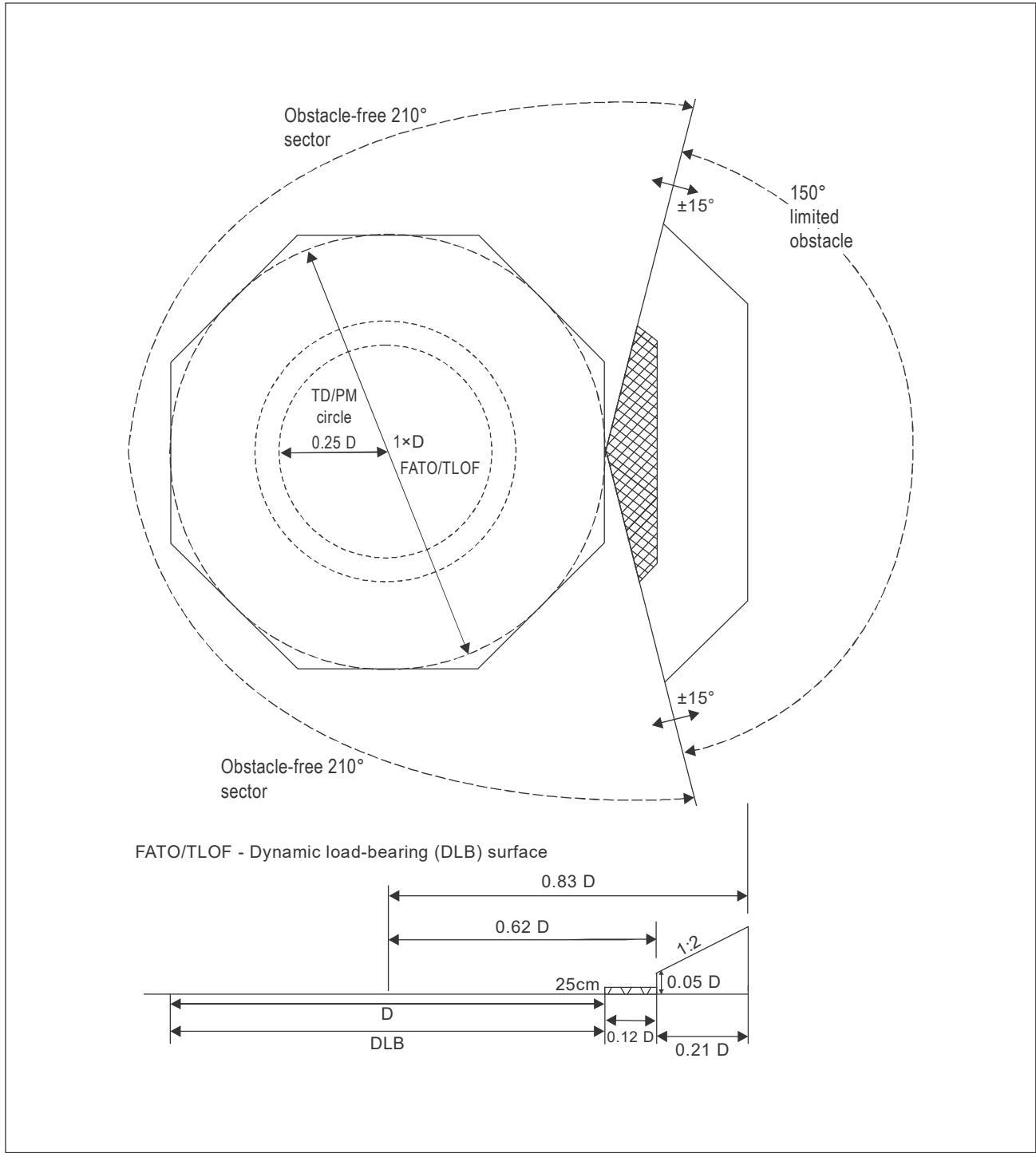
Figure I-3-1. Helideck obstacle limitation sectors and surfaces for a FATO/TLOF of 1 D
Part I. Offshore heliports Chapter 3. Physical characteristics
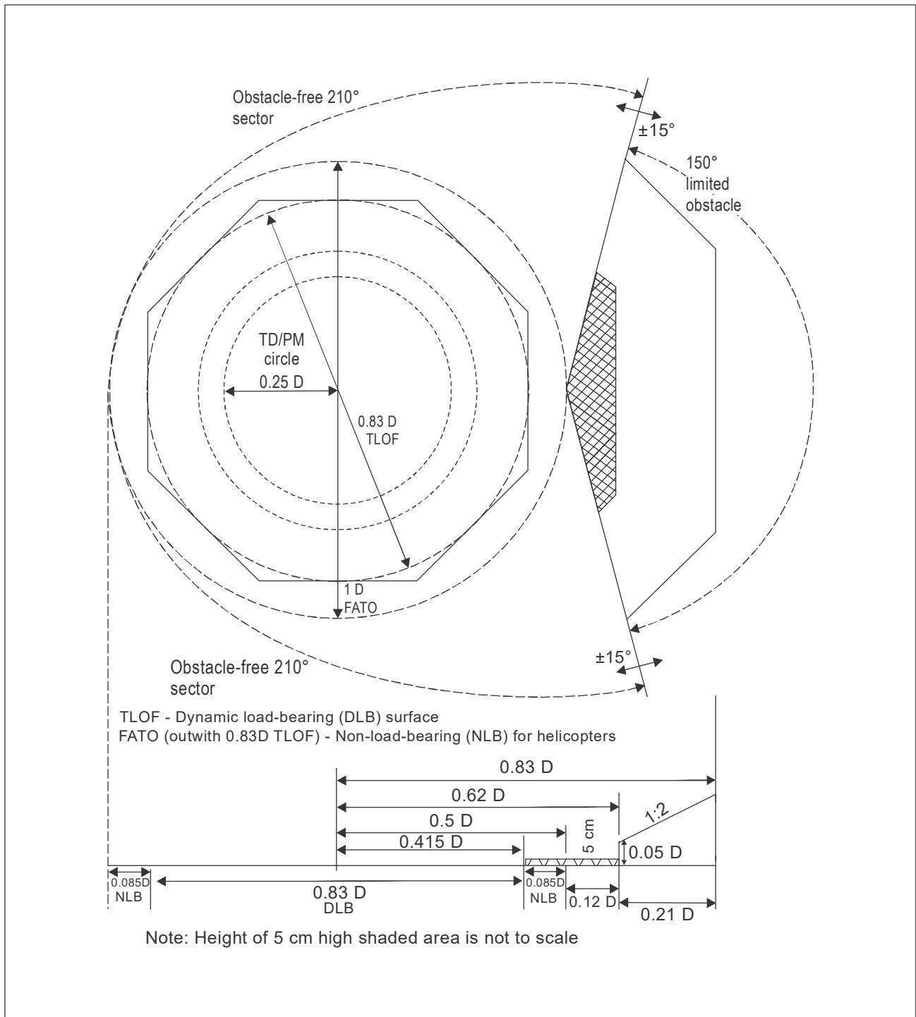
Figure I-3-2. Helideck obstacle limitation sectors and surfaces for a FATO/TLOF less than 1 D (particular example is for a minimum-size 0.83 D TLOF)
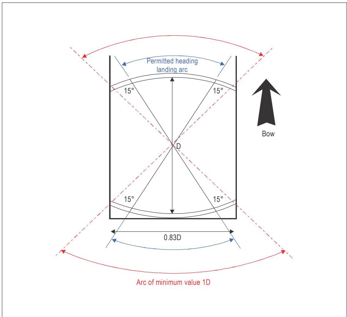
Figure I-3-3. Shipboard permitted landing headings for limited heading operation
Chapter 4
OBSTACLE ENVIRONMENT
4.1 DESCRIPTION OF SURFACES — HELIDECKS
4.1.1 For any particular type of single main rotor helicopter, the final approach and take-off area (FATO) should be sufficiently large to contain a circle of diameter D equal to the largest dimension of the helicopter when the rotors are turning. Except for the presence of objects essential for the safe operation of helicopters, the FATO, encapsulating a usually hypothetical D-circle, should remain unobstructed. Acceptance of essential objects within the periphery of the FATO, intended to be an obstacle-free area to contain the design helicopter, should be subject to a risk assessment (see Appendix I-A).
4.1.2 From a point on the periphery of the above mentioned D-circle, an obstacle-free approach and take-off sector should be provided which extends over an angle of at least 210 degrees. Within this sector, obstacle accountability should be considered out to a distance from the periphery of the FATO that will allow for an unobstructed departure path appropriate to the least well performing helicopter the FATO is intended to serve. The height limitation for obstacles in the obstacle-free sector (OFS) is 25 cm (10 in) for a TLOF of greater than 16 m (52.5 ft) and/or 1 D or greater, but ideally no greater than 15 cm (6 in), and 5 cm (2 in) for a TLOF 16 m (52.5 ft) or less and/or less than 1 D. For helicopters that are operated in performance class (PC) 1 or 2, the horizontal extent of this distance from the edge of the FATO will be based on the one-engine-inoperative capability of the type to be used.
4.1.3 The bisector of the 210-degree OFS will normally pass through the centre of the D-circle. In exceptional cases, for the avoidance of immovable obstacles that may be located on one side towards the edge of the obstacle-free sector boundary, when supported by an aeronautical survey it may be permitted to swing the OFS by up to 15 degrees either clockwise or anti-clockwise to clear an object — as illustrated in Chapter 5, Figure I-5-3. If it is necessary for the 210-degree sector to be swung, then it is normal practice to swing the 180-degree falling gradient in the same direction and by the corresponding amount, unless by doing so an obstacle is then introduced below FATO level, which compromises the falling gradient.
4.1.4 To account for the loss in height of a helicopter following an engine failure occurring during the early stages of the take-off manoeuvre, it is required that a clear zone (CZ) be provided below landing area level covering a sector of at least 180 degrees with its origin based at the centre of the D-circle. The falling gradient is measured downwards to the sea surface from the edge of the (approximately 1.5 m (5 ft)) safety netting or safety shelving on a gradient of 5:1 (5 units vertically (downwards) for every 1 unit horizontally (outwards)). The surface should extend outwards for a distance that will allow for safe clearance from obstacles below the landing area in the event of an engine failure based on the least well performing helicopter that is serviced by the FATO. For helicopters operated in performance class (PC) 1 or 2, the horizontal extent of this distance from the landing area will be based on the one-engine inoperative capability of the helicopter type in use. All objects that are underneath the final approach and take-off paths will need to be assessed.
4.1.5 As mentioned, the OFS should extend over a sector of at least 210 degrees, but, obstacles permitting, may extend over the whole 360-degree sector. An obvious example of where a 360-degree OFS could apply is for a facility where the helideck sits above the highest point at an elevation where there is no other significant topside structure present. However, these kinds of facilities (e.g. monopods) are the exception to the rule and it is more likely that obstacles will be present in the remaining limited obstacle sector that protrudes above the level of the FATO on the obstacle side. A limited obstacle sector (LOS) is therefore normally present and will occupy the remaining sector, covering an arc of up to 150 degrees.
4.1.6 The LOS consists of two segments: the first (inner) segment, which adjoins the periphery of the FATO on the obstacle side, will extend to a horizontal distance of 0.12 D from the edge of the FATO and will have the same shape characteristics as the physical shape of the landing area — as newbuild helidecks are most commonly octagonal or hexagonal in shape, this will mean the extent of the first (and second) segments of the LOS, will be lines parallel to the TLOF perimeter marking which is required to follow the physical shape of the helideck (or shipboard heliport). This is illustrated in Chapter 3, Figures I-3-1 and I-3-2. The height limitation for obstacles in the first segment of the LOS (at 0.12 D) is 25 cm (10 in) for a TLOF of greater than 16 m (52.5 ft) and/or 1 D and 5 cm (2 in) for a TLOF 16 m (52.5) or less and/or less than 1D. Guidance on obstacle-protected surfaces for non-standard square or circular helidecks is given in Section 4.5.
4.1.7 The second segment of the LOS extends from the periphery of the first segment for a further distance of 0.21 D (i.e. a total distance of 0.33 D from the periphery of the FATO). Obstacle limitation within the second segment is more relaxed, most limiting at the forward edge of the second segment where obstacle height restriction is limited to 0.05 D based on the diameter of the FATO. From this point, the obstacle limitation surfaces extend on an upward gradient that equates to a slope of 2 units horizontally for every one unit vertically — the 1:2 slope extends from 0.12 D to 0.33 D. Once beyond 0.33 D from the edge of the FATO, obstacle height restrictions no longer apply.
4.1.8 Obstacles that penetrate either segment of the LOS should be removed or modified so that they no longer constitute an infringement. Where an immovable object penetrates the LOS, whether in the first and/or second segment (an example of this could be the leg of a self-elevating jack-up facility which is situated right in the LOS — clearly the leg is neither moveable nor modifiable), it may be possible to mitigate the effects of the penetration by applying a prohibited landing sector (PLS) marking, which ensures that a helicopter cannot land with the tail towards the obstacle, where the obstacle is not within the pilot’s field of view. The application of a PLS, including the characteristic of the marking, is described in more detail in Chapter 5, 5.11. The benefit of a PLS marking may be maximized by applying it in conjunction with an offset touchdown/positioning marking (the offset marking is discussed in further detail in Chapter 5, 5.7.2 and illustrated in Figure I-5-3, Example B). The application of a PLS, with or without a TD/PM, should not be used as an easy (and often temporary) solution to justify the presence of unwanted obstructions; it is always preferable, where practical, to remove, to relocate or to modify an obstacle which would otherwise penetrate through the surface of the LOS.
4.1.9 Experience suggests there can be pressure to accommodate obstacles close to the extended boundary of the OFS but outside the second segment on the limited obstacle side, where there are no specific obstacle restrictions/limitations. The presence of a large solid object, whether a new permanent feature or a temporary one, in close proximity to the helideck has potential to promote turbulence over the helideck in some wind conditions and should be avoided. This issue is discussed in depth in Chapter 3, 3.2 — but to avoid doubt, any proposed siting near to the helideck should be subjected to appropriate modelling before it is introduced. Equally, locating a non-rigid (flexible) structure, such as a long whip aerial, in the area immediately adjacent to the helideck can have an impact on the safety of helicopter operations if the whip aerial should bend into the OFS under the force of an approaching helicopter’s rotor downwash. It is therefore recommended that flexible objects, such as whip aerials, are not sited right at the edge of the OFS where they could bend into the protected area.
4.2 DESCRIPTION OF SURFACES — SHIPBOARD HELIPORTS
4.2.1 The surfaces, sectors and warnings described above apply equally in the majority of the cases for shipboard heliports. This includes bow and stern-mounted heliports and purpose-built heliports cantilevered over the side of a vessel. Operators with these types of arrangements should therefore read all sections above. However, there are also so-called non-standard arrangements which do not apply the same obstacle limitation surfaces as a helideck. These ‘exceptions’ are described in the remaining paragraphs of this section.
4.2.2 A unique arrangement for the obstacle-protected surfaces and sectors is applied for a purpose-built or non-purpose-built shipboard heliport, typically, but not necessarily, located midships on the centreline of the vessel (e.g. a midships heliport on a tanker — Figure I-1-5.). In this case, an OFS (sometimes known as the clear area) is provided between two limited obstacle sectors (sometimes designated as the manoeuvring zones — forward and aft). Being sandwiched between the OFS provides an obstacle-free funnel for approach and departure, which allows a helicopter operating across the vessel (from port to starboard or vice-versa) to do so free of obstacles and, by providing an LOS (manoeuvring zone) either side of the approach and departure funnel, affords the helicopter some degree of lateral movement by providing obstacle restriction forward and aft in the LOS, for a helicopter operating athwartships to the heliport. The sectors and surfaces applied uniquely to this type of arrangement are illustrated in Figure I-4-1. The markings for this arrangement are addressed in Figure I-5-4.
4.2.3 A further non-standard arrangement is applied to a non-purpose-built landing area located on a ship’s side. In this case, the minimum FATO, always coincident with the TLOF, is a circle of 1 D, based on the design helicopter. A CZ, free of obstacles above 25 cm (10 in), is established at the ship’s side adjacent to the FATO, for a distance of 1.5 D. This is referred to as the CZ extended at the ship’s side. Surrounding the FATO is a manoeuvring zone (MZ), having a width of 0.25 D, which tapers out from the midpoint of the D-circle to a distance of 2 D measured at the ship’s side. Two areas adjacent to the ships side inside the inner boundary of the MZ but outside the FATO are referred to as limited obstacle areas (LOA) where obstacles are permitted but should not exceed a maximum height of 25 cm (10 in). Similar obstacle restrictions apply to the MZ which surround the FATO (also known as the CZ). The obstacle limitation surfaces and sectors for this arrangement are illustrated in Figure I-4-2.
Note.— Where the FATO is 16 m (52.5 ft) or less, the maximum height of obstacles permitted in the MZ and LOA is correspondingly reduced from 25 cm (10 in) to 5 cm (2 in).
4.2.4 For a non-purpose-built landing area located on a ship’s side, which by design utilizes an area of the ship’s decking, the tight control of obstacles on the ship’s surface is not as straightforward as it would be for any purpose-built heliport structure. In this circumstance it is necessary to develop a system for mapping of obstacles so the operator is aware of their location and any potential impact on helicopter operations. A procedure for mapping of obstacles on non-purpose-built shipboard heliports is fully described in Section 4.6.
Note.— Where the D-value is 16 m (52.5 ft) or less the obstacle height limitation around the landing area is restricted to 5 cm (2 in).
4.3 TEMPORARY COMBINED OPERATIONS
4.3.1 Temporary combined operations are essentially arrangements where two or more offshore facilities, whether fixed or floating, are in close proximity ‘alongside’ or ‘pulled away’ from one another. They may be in place for a matter of hours, days, or for up to several years. On occasion, combined operations may include vessels working alongside one or more fixed and/or mobile facilities. The close proximity of facilities and/or vessels to one another is likely to entail one or more of the helidecks/shipboard heliports being operationally restricted due to one or more of the obstacle-protected surfaces being compromised and/or due to adverse environmental effects of one installation on the landing area of another (environmental effects are discussed in more detail in Chapter 3, 3.2). For example, the facility pictured in the centre of Figure I-4-3 has obstacle-protected sectors and surfaces (extended OFS as well as the falling gradient) that are severely compromised by the proximity of the other two facilities. A landing prohibited marker (a yellow cross on a red background) is in place on the drilling facility (centre) to prevent operations to the helideck. Where temporary combined operations are planned, prior to helicopter operations, an assessment should be completed to assess the physical as well as the environmental impact of the arrangements and to assess any flight restrictions or limitations, including prohibitions, which might need to be disseminated to aircrew (usually a temporary instruction). Helidecks (or shipboard heliports), which are determined to be unavailable, should display the relevant landing prohibited marker by day while, at night, all aeronautical lights should be extinguished.
4.3.2 Quite often, combined operations will involve both facilities and/or vessels being in close proximity alongside one another, where the effect of one facility on the helideck obstacle-protected surfaces of another is immediately obvious. However, during the life of a combined arrangement, there may also be periods when mobile facilities and/or vessels are pulled away to a stand-off position, which could be at some distance. It will be necessary for operators to reappraise the situation for a combined operation in the stand-off configuration. With one or more installations or vessels pulled away, there may be an opportunity to relax or remove limitations imposed for the ”alongside” configuration. This is normally an assessment for the helicopter operator to make.
4.4 MULTIPLE PLATFORM CONFIGURATIONS/LOCATION OF STANDBY VESSELS
4.4.1 Where two or more fixed structures are permanently bridge-linked, the overall design should ensure that the sectors and surfaces provided for the helideck are not compromised by other modules which may form part of a multiple platform configuration. It is also important to assess the environmental impact of all modules on the flying environment around the helideck. This is discussed in further detail in Chapter 3, 3.2.
4.4.2 Where there is an intention to add new modules to an existing platform arrangement, it is important to make an assessment of the potential impact that additional platforms might have on helideck operations. This will include an assessment of the sectors and surfaces for the helideck which should not be compromised due to the location of a new platform, or modification to an existing platform. This will include a detailed analysis of the environmental impact on the flying environment around the helideck, which is addressed in further detail in Chapter 3, 3.2.
4.4.3 The presence of a Standby Vessel in the vicinity of an active helideck operation is a legal requirement in many offshore sectors. The location of the Standby Vessel, and any other vessel present on the sea surface, should not compromise the safety of the helicopter operation. It is prudent to re-emphasize the following, based on the note from Annex 14 — Aerodromes, Volume II — Heliports, Section 4.2.14:
Note.—Where there is a requirement to position, at sea surface level, one or more offshore support vessel(s) (e.g. a Standby Vessel) [or tanker] essential to the operation of a fixed or floating offshore facility, but located within the proximity of the fixed or floating offshore facility[‘s obstacle-free sector (OFS)], any offshore support vessel(s) would need to be positioned so as not to compromise the safety of helicopter operations during take-off departure and/or approach to landing.
4.5 GUIDANCE FOR OBSTACLE-PROTECTED SURFACES FOR SQUARE OR CIRCULAR HELIDECKS
4.5.1 Earlier, a description of surfaces for helidecks including the characteristics of the limited obstacle sector (LOS) which assumes in each case that the shape of the helideck consists of an octagon or a hexagon, was addressed. This is because the great majority of newly built helidecks, and purpose-built shipboard heliports, are configured for one of these shapes. However, helidecks and shipboard heliports may also be quadrilateral (mainly square) or circular, so it is important to provide some guidance on the characteristics of the obstacle-protected surfaces for square and circular helidecks and shipboard heliports. While evidently there are any number of different variations of shapes possible (as long as the extent of the dynamic load-bearing area provided is able to accommodate the usually hypothetical D-circle), characteristics for the sectors and surfaces of non-standard shapes will, in the main, have a resemblance to one of the schemes used for octagonal or hexagonal helidecks (illustrated in Chapter 3) or to arrangements for circular or square helidecks or shipboard heliports, as illustrated in this section of Chapter 4 — see Figures I-4-4 to I-4-7.
4.5.2 The extent of the 150° LOS segments in the case of a helideck or shipboard heliport that is any shape other than circular will be represented by straight lines parallel to the perimeter of the TLOF. The limiting dimensions of the two segments for the LOS measured from the inboard edge of the landing area are similar — the first (inner) sector comprising a 0.12 D segment where the height limitation for obstacles is 25 cm (10 in) for helidecks of 1 D and greater provided they are also greater than D=16 m (52.5 ft), or 5 cm (2 in) for helidecks where the D-value is 16 m (52.5 ft) or less and/or is less than 1 D. The second segment extending out a further 0.21 D originating at a height of 0.05 D above the helideck surface at the inner edge rises on a 1:2 slope out to an overall distance of 0.33 D. For circular helidecks or shipboard heliports, the segments and sectors represented by straight lines are replaced using sectors shaped in an arc. The overall dimensions are ostensibly the same, but the penetration of the surface at certain points along the arc is somewhat more limited. This is illustrated below: Figures I-4-4 and I-4-5 address 1.0 D helideck/shipboard heliport arrangements, and Figures I-4-6 and I-4-7 address 0.83 D helideck/shipboard heliport arrangements.
4.6 MAPPING OF OBSTACLES ON NON-PURPOSE-BUILT SHIPBOARD HELIPORTS
4.6.1 This section provides guidance on the completion of a helicopter landing area plan for the benefit of helicopter operators. The helicopter landing area plan provides additional information regarding the vessel’s surface and the helicopter landing area (a non-purpose-built ship’s side arrangement). The plan should be prepared in advance of any intended helicopter operations and should be stored on the vessel and provided to the helicopter operator. Amendments to the plan should be made when appropriate.
4.6.2 The system described assumes paper versions of a helicopter landing area plan would be made, but this procedure lends itself just as easily to an electronic form of dissemination. Whichever method is used to create and file the helicopter landing area plan, it should include templates annotated with vessel-specific data, including any obstructions within the FATO/TLOF (a 1 D circular CZ) or within the manoeuvring zone or LOA. Templates should be annotated with the obstructions that exceed the height limits prescribed for the specific areas in Figure I-4-2 — for the LOA and the MZ the obstruction height limit is 25 cm (10 in) while for the FATO/TLOF the obstruction height limit is 2.5 cm (1 in) (if the FATO/TLOF is 16 m (52.5 ft) or less the obstruction height limit for the LOA and MZ are reduced to 5 cm (2 in)).
4.6.3 The template should ideally include a photograph showing the ship’s helicopter operating area to provide a helicopter pilot with a quick reference guide to the ship, the helicopter operating area(s) and notable obstructions. Care in recording the nature and location of obstructions on the template is very important. Accurate measurements of the position and height of all significant obstructions relative to the helicopter touchdown markings should be taken.
4.6.4 Any identified obstacles should be colour-coded on the template and painted on the physical surface of the vessel. Colour-coding and painting will define the safety significance of an obstruction. For the purpose of standardization, the following paint colour schemes are recommended:
a) red and white painted stripes should be used for marking the position of notifiable objects within the MZ, the CZ or the LOA where they exceed the height limits for these zones — see Figure I-4-8:
-
objects within the CZ of a height exceeding 2.5 cm (1 in);
-
objects outside the CZ but within the MZ or LOA which exceed a height of 25 cm (10 in); and
-
where the diameter of the CZ is 16 m (52.5 ft) or less limitation in the MZ and LOA applies to objects which exceed a height of 5 cm (2 in);
b) yellow and black painted stripes should be applied for marking objects beyond the MZ to which it is considered appropriate to draw the attention of the helicopter pilot. Yellow and black stripes may also be used to mark objects within the MZ, the CZ and the LOA which, though below the height limits for these sectors, are still considered appropriate to draw to the attention of the helicopter pilot.
4.6.5 Vessel details should be included on the template and a photograph that shows the location of the helicopter landing area should be scanned and forwarded to the helicopter operator in a colour presentation. An indication of the scale used should also be provided.
4.6.6 Figure I-4-8 shows an example of a helicopter landing area plan for a ship’s side non-purpose-built heliport on a tanker. The red/yellow/green colour coding presentation corresponds to the absolute height of the obstruction above deck level. The Butterworth Lid at 30 cm (1 ft) is shown in green. The tank wash line at 60 cm (0.6 m, 2 ft) is shown in yellow and the dominant vents at 230 cm (2.3 m, 7.5 ft) are shown in red.
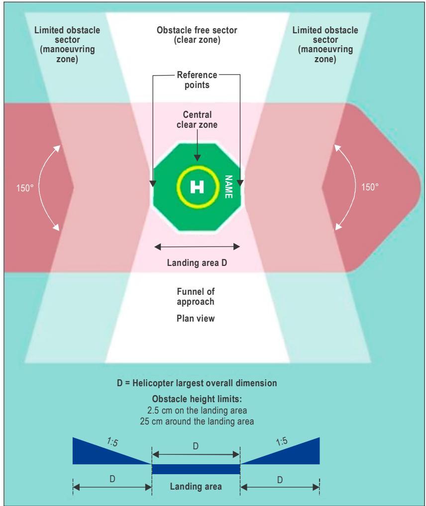
Figure I-4-1. A purpose-built or non-purpose-built midship centreline landing area1
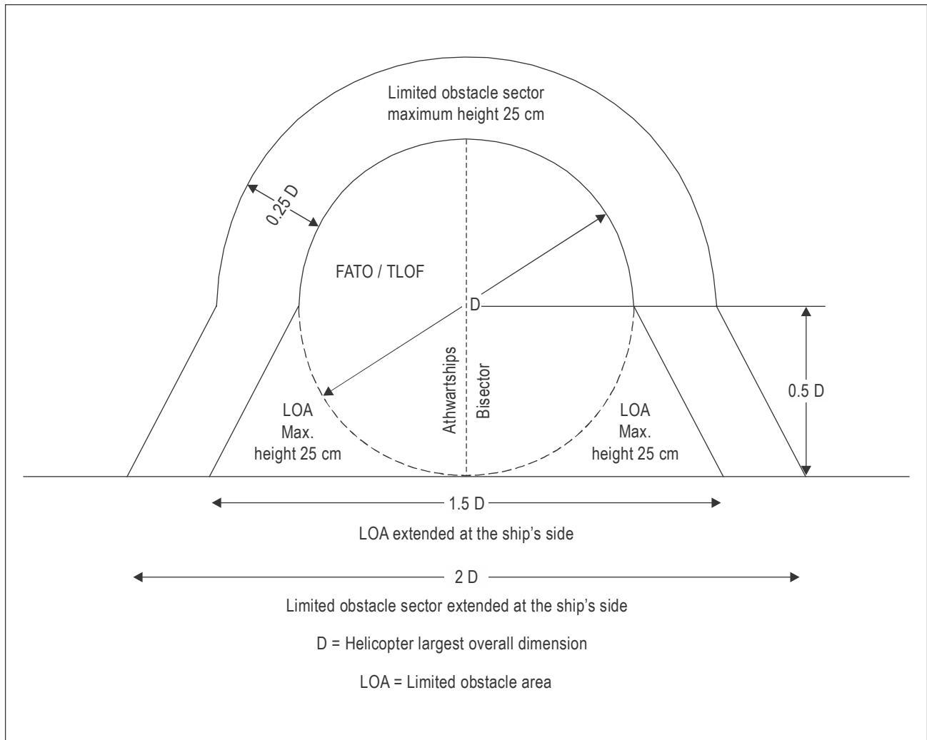
Figure I-4-2. Ships-side non-purpose-built heliport obstacle limitation sectors and surfaces
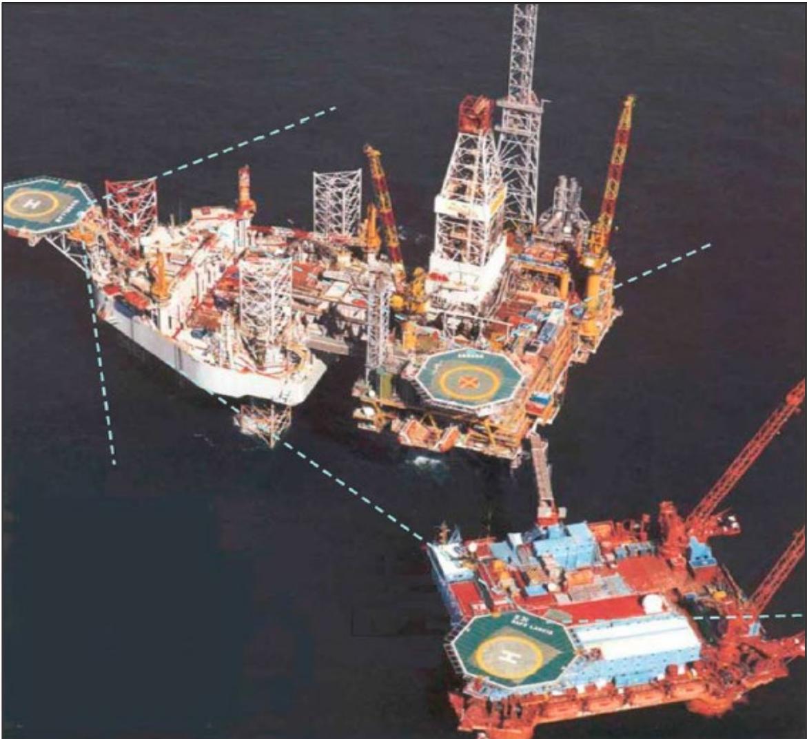
Figure I-4-3. A temporary combined operation showing relative position of each helideck 210º sector
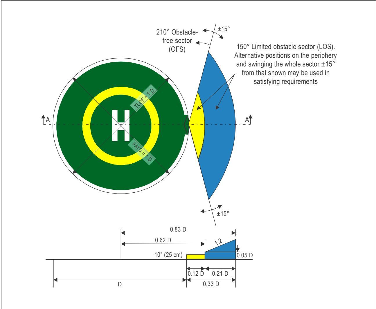
Figure I-4-4. Helideck obstacle limitation sectors and surfaces for a 1 D circular FATO and coincidental TLOF
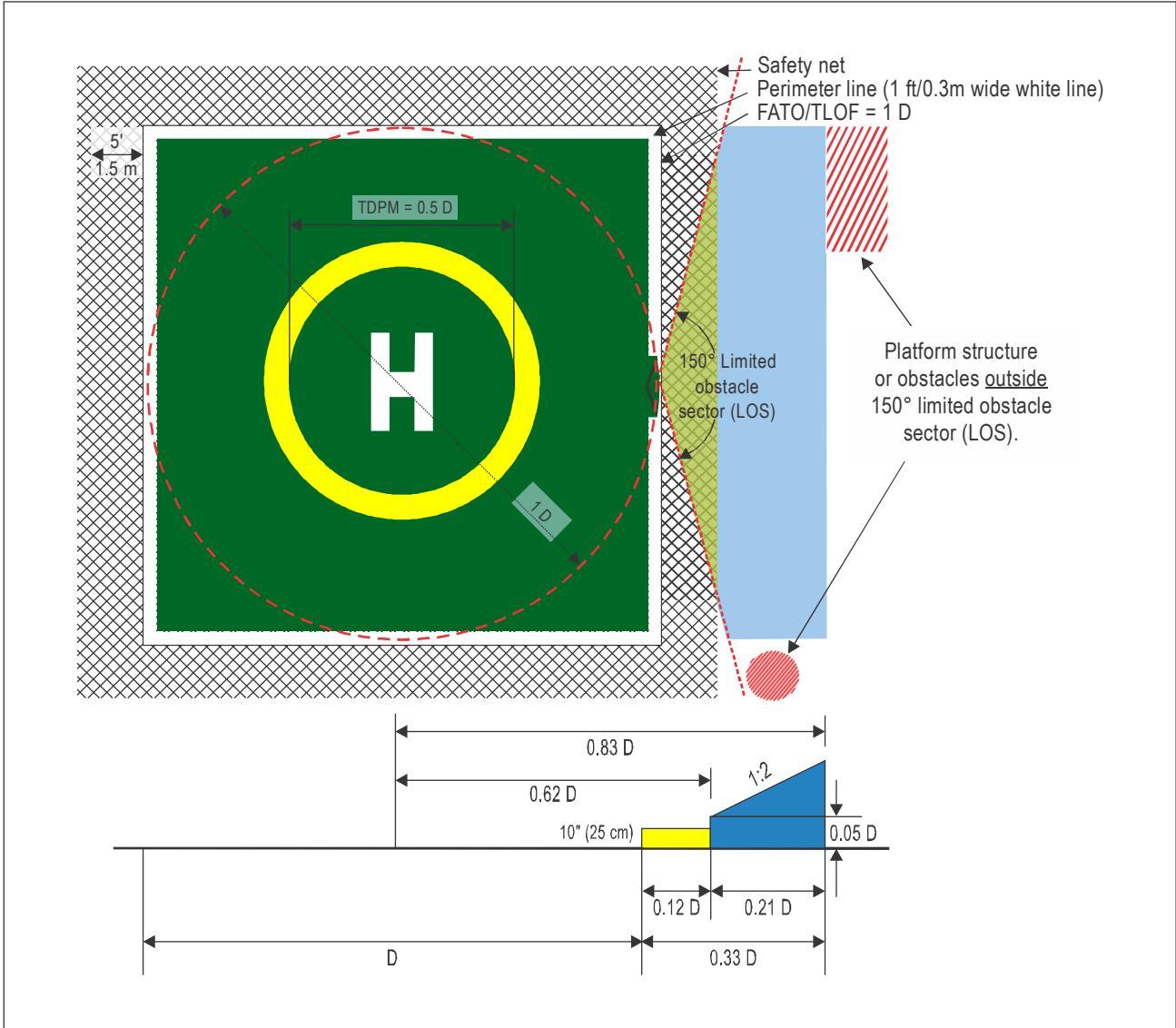
Figure I-4-5. Helideck obstacle limitation sectors and surfaces for a 1 D square FATO and coincidental TLOF
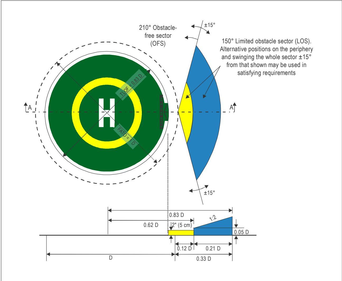
Figure I-4-6. Helideck obstacle limitation sectors and surfaces for a 0.83 D circular TLOF with collocated 1 D FATO
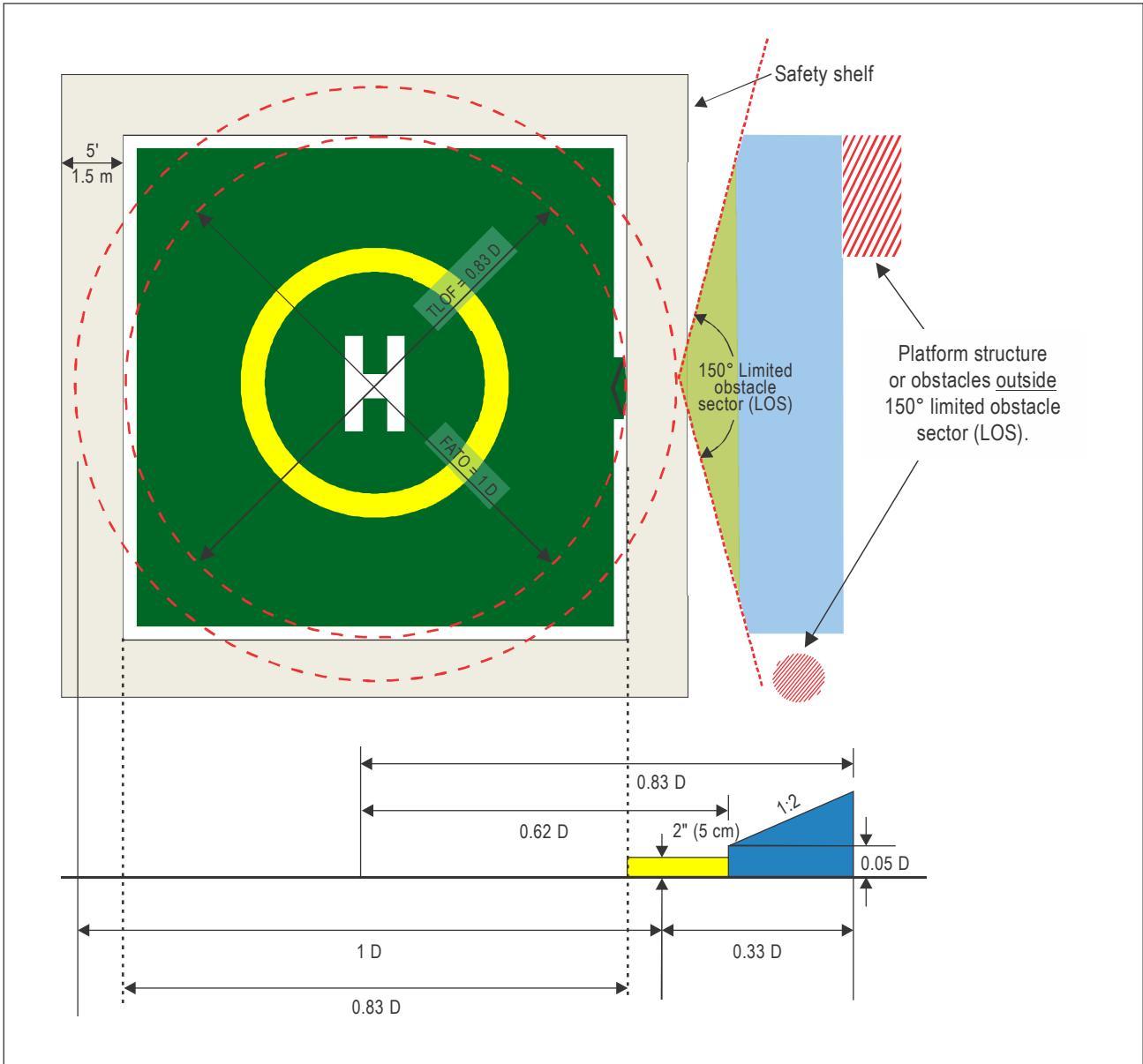
Figure I-4-7. Helideck obstacle limitation sectors and surfaces for a 0.83 D square TLOF with collocated 1 D FATO
Part I. Offshore heliports Chapter 4. Obstacle environment
| Ship details | |
| Date compilled | 18 November 2008 |
| Name of ship | SAMARINDA |
| Company name | Carthusian Shipping Line |
| Max Deck Height | 26m |
| D Value | 19m |
| Contact name | Capt David Wilkinson |
Obstruction
| ltem | Description | Height |
| - | Tank wash line | 0.6m |
| Vent | 2.3m | |
| Butterworth Ltd | 30cm | |
| Vent | 2.3m | |
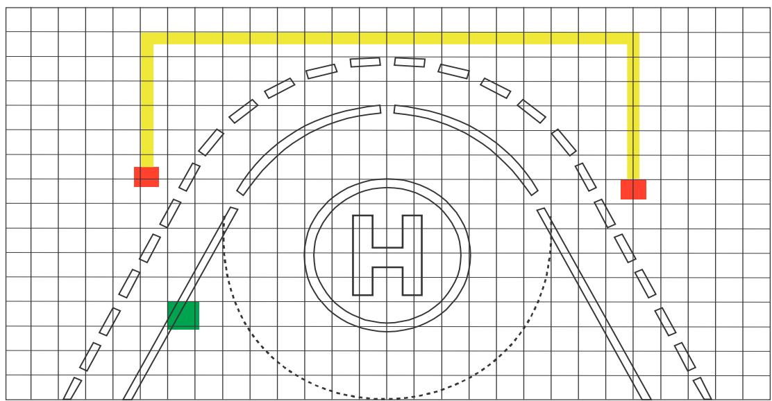
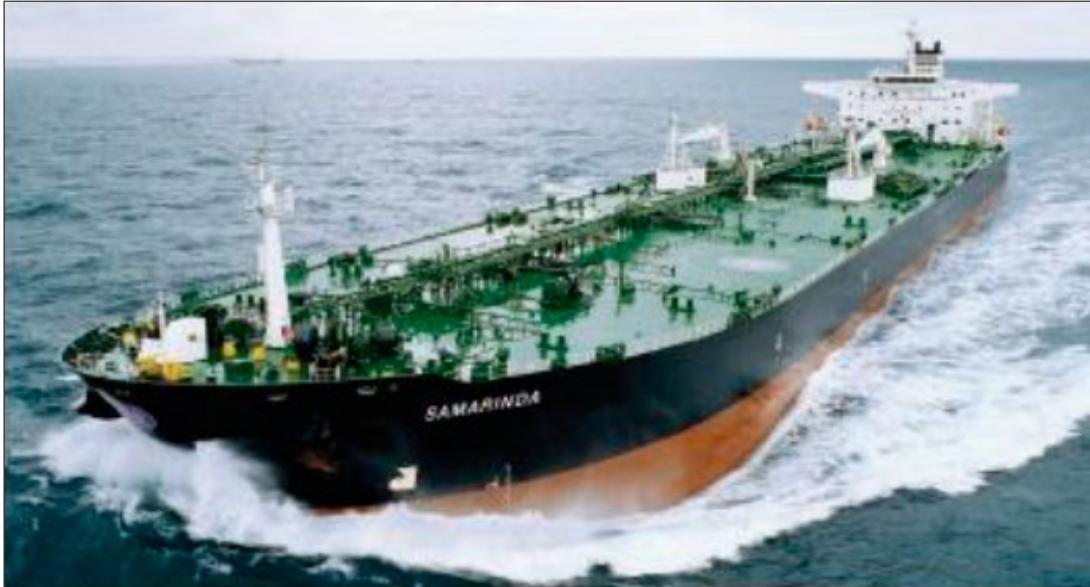
Figure I-4-8. Helicopter landing area plan for a ship’s side non-purpose-built heliport on a tanker2
Chapter 5
VISUAL AIDS — MARKING AND LIGHTING
5.1 GENERAL
5.1.1 A helideck or shipboard heliport intended for use by day only, in good visibility conditions, will need to display markings only, while a helideck or shipboard heliport intended for use at night and/or in reduced visibility conditions by day and night, will need to display appropriate lighting in addition to defined markings. The marking and lighting aids described in this chapter are, in some cases, amplifications of those included in Annex 14 — Aerodromes, Volume II — Heliports and have been developed primarily in support of visual heliport operations.
5.1.2 It is not intended that this chapter should address every option of a detailed marking scheme for non-purpose-built shipboard heliports, given that the precise layout, including the surface colour of the main deck on which markings will be overlaid, can vary from ship to ship. As the underlying surface colour can vary considerably, some discretion will need to be exercised in the colour selection of paint schemes. The primary objective in every case should be to ensure that heliport markings achieve a good contrast with the surface of the ship and are fit-for-purpose with regards to the maritime environment in which the ship will be operating. Figure I-5-1 illustrates the difficulties that may be encountered in the pursuit of this objective. A specific marking scheme for a non-purpose-built shipboard heliport (ship’s side arrangement) is illustrated in detail in Figure I-5-11. Specific marking and lighting schemes for winching areas are addressed in detail in Chapter 7.
5.1.3 It has been found that on surfaces of light colour, such as natural aluminium, the conspicuity of white and yellow markings, in particular, can be improved by outlining them with a thin black line (typically 10 cm (4 in)) or by overlaying white or yellow markings on a painted black background (proven to be particularly effective for enhancing the heliport/helideck name marking). An example of how this can work in practice is illustrated in Figure I-5-6.
5.1.4 Annex 14 does not currently go into detail on the issue of acceptable tolerances for the size and spacing of marking and lighting. It is for the appropriate authority to determine what tolerance should be allowed giving due diligence to the clear interpretation of visual cues and the safety of operations at all times, i.e. in the interest of providing clear and effective visual cues being interpreted from the air, there may be more allowance given for a slightly oversized marking than for one which is too small, with the exception of where the given specifications are treated as maximum dimensions. Wherever practical, it is recommended that the font type Clearview Hwy-5W is used.
5.1.5 As well as providing effective unambiguous markings and lighting on a helideck (or shipboard heliport) there may be an operational requirement to display the name of a fixed or floating facility (or vessel) in other locations so they are readily identifiable from the air (and sea) from all normal angles and directions of approach. In this case, identifiers should be unique, simple and consistent with other information given to aircrew (e.g. radio-telephony (R/T) call sign, name on a pre-flight helideck information plate (HIP) (see Chapter 2)) and be readable, at ranges that are at or beyond the helicopter’s landing decision point (LDP), both by day and, where required, by night. Effective side signage, which could make use of available technologies such as retro-reflective panels, LED clusters or fibre optic systems, will assist aircrew with early positive recognition of the facility or vessel and so help to minimize the possibility of landing on the wrong rig.
Note.—Other simple measures may be introduced to mitigate the incidence of an undesirable landing such as increasing the size of the heliport name marking to 1.5 m (5 ft) (i.e. above the minimum dimensions specified in Chapter 5, 5.8.1), or painting a second heliport name marking aligned with the normal direction of approach for a bow-mounted helideck with the vessel heading steaming into wind (i.e. a second heliport name marking painted between the outboard edge of the shipboard heliport and the yellow TD/PM circle facing toward the helicopter will assist the pilot with positive recognition earlier on in the approach), and by extinguishing the touchdown and lift-off area (TLOF) floodlights and or circle-H lighting, at night, in the case where a helideck or shipboard heliport is unprepared and potentially unsafe when it is not expecting to receive helicopters.
5.2 WIND DIRECTION INDICATOR
5.2.1 An offshore facility or ship should be equipped with at least one wind direction indicator to provide a visual indication of the wind conditions prevailing over the facility during helicopter operations.
5.2.2 The location of the primary wind direction indicator should be in an undisturbed airstream avoiding any effects caused by nearby structures (see also Chapter 3, 3.2.2), and unaffected by rotor downwash from the helicopter. The location of the wind direction indicator should not compromise the established obstacle protected surfaces (see Chapter 4). Typically, a primary wind direction indicator will consist of a coloured windsock.
5.2.3 The windsock should be easy visible to the pilot on the approach (at a height of at least 200 m (656 ft)), in the hover and while touched down on the surface of the TLOF, and prior to take-off. Where these operational objectives cannot be fully achieved by the use of a single windsock, consideration should be given to locating a second windsock in the vicinity of the helideck or shipboard heliport, which could also be used to indicate a specific difference between the local wind over the TLOF and the free stream wind at the installation or ship (which the pilot will reference for an approach).
5.2.4 A windsock should be a truncated cone made of a suitable lightweight fabric with a minimum length of at least 1.2 m (4 ft), a diameter at the larger end of at least 0.3 m (1 ft) and a diameter at the smaller end of at least 0.15 m (0.5 ft). The colour should contrast well with the operating background in the offshore environment. Ideally a single coloured windsock, preferably orange or white, should be selected. However, where a combination of colours is found to provide better conspicuity against a changing operating background, orange and white, red and white or black and white colour schemes could be selected, arranged as five alternate bands with the first and last band being the darker colour.
5.2.5 If a helideck or shipboard heliport is intended to be operated at night, the windsock(s) will need to be illuminated. This can be achieved by internal illumination, perhaps a floodlight pointing through the wind cone. Alternatively, the windsock can be externally highlighted using, for example, area floodlighting. Care should be taken to ensure that any system used to illuminate a windsock highlights the entire cone section while not presenting a source of glare to a pilot operating at night.
5.3 HELIPORT IDENTIFICATION (H) MARKING
5.3.1 A heliport identification marking should be provided for a helideck or a shipboard heliport in the form of a white “H” with a height of 4 m (13 ft), an overall width not exceeding 3 m (10 ft) and a stroke width not exceeding 0.75 m (2.5 ft). In circumstances where the D-value of a helideck or shipboard heliport is less than 16 m (52.5 ft), Annex 14, Volume II permits the size of the marking to be reduced such that the dimensions of the “H” are 3 m (10 ft) (in height) with an overall width not exceeding 2.25 m (7.4 ft) and a stroke width not exceeding 0.5 m (1.6 ft). A typical ‘standard-size’ heliport identification marking is shown in Figure I-5-2.
5.3.2 A heliport identification “H” marking should ideally be located in the centre of the final approach and take-off (FATO), except where the results of an aeronautical survey indicate that an offset marking may be beneficial to helicopter operations and still allow for the safe movement of personnel around the helicopter, in which case the centre of the “H” may be offset by up to 0.1 D towards the outboard edge of the FATO. An example of where this measure may be used could be for an oversized helideck — one that exceeds the minimum 1 D dimensional requirement — but that also has immovable obstructions close to the inboard perimeter, in the limited obstacle sector (LOS). In this case, moving the touchdown marking location away from the centre of the FATO towards the outboard edge will improve clearances from dominant obstacles, while, in theory, still facilitating adequate on deck clearance around the helicopter for the safe movement of passengers and for the efficiency of helideck operations, such as refuelling. A comparison of the location of the touchdown markings, whether centralized or fully offset, are shown in Figure I-5-3, examples A and B.
5.3.3 The heliport identification marking, regardless of whether it is based on the centre of the FATO or not, should always be established in the centre of the touchdown/positioning marking circle (see Chapter 5, 5.7). For a helideck, and for a purpose-built shipboard heliport, the centreline of the cross bar of the “H” should be passed through by the bisector of the obstacle-free sector (OFS). Where, in exceptional cases, it is necessary for the chevron marking (see Chapter 5, 5.9) to be swung for a helideck (e.g. to clear an immovable obstacle which might otherwise penetrate the 210-degree sector), it will be necessary to swing the “H” marking by the corresponding angle, to indicate to aircrew on approach that the sector has been swung. The maximum swung sector should not exceed ± 15 degrees from the normal for the OFS. A ‘swung’ heliport identification “H” marking is illustrated in Figure I-5-4.
5.4 MAXIMUM ALLOWABLE MASS MARKING
5.4.1 A maximum allowable mass marking should be arranged so as to be readable from the preferred final approach direction (on a fixed facility this will usually be in a direction lining up with the prevailing wind direction for the facility).
5.4.2 The maximum allowable mass marking should be expressed as a one-, two- or three-digit number corresponding to the maximum allowable mass of the heaviest helicopter permitted to use the TLOF in accordance with the structural requirements detailed in Chapter 3, 3.1. In most cases the maximum allowable mass marking will correspond to the maximum (certificated) take-off mass (MTOM) for the design helicopter type, but this need not necessarily be the case if the structural calculations performed for the helideck or shipboard heliport confirm a structural limit that is different from (i.e. exceeding) the MTOM of the design helicopter. Where the MTOM is expressed in metric tonnes, the suffix “t” will be painted with the numerical marking. For States where the marking is expressed as an imperial measure i.e. in lbs, it is not appropriate to suffix with a “t” — in this case no suffix is provided.
5.4.3 For a maximum allowable mass marking expressed in metric units the minimum requirement is to depict a marking rounded to the nearest 1 000 kg. A Recommendation is made in Annex 14, Volume II for the marking to be expressed to the nearest 100 kg. The following examples are offered, based on current manufacturer derived data. The figures should be regarded for illustrative purposes only, and as a helicopter’s MTOM can increase, especially following introduction to service of a new type, designers are advised to verify specific helicopter data with the manufacturer or offshore helicopter operator:
Bolkow 117: MTOM 3 200 kg is expressed as “03 t” or “3.2 t”
Super Puma AS 332L: MTOM 8 599 kg is expressed as “09 t” or “8.6 t”
Sikorsky S92: MTOM 12 565 kg is expressed as “13 t” or $\ " 1 2 . 6 \ : \mathrm { t } ^ { \prime \prime }$
5.4.4 For a maximum allowable mass marking expressed in imperial (customary to the United States) units, the recommended method of designating the helideck limitations is to indicate the MTOM of the helicopter in terms of a twoor three-digit number with one decimal point rounded to the nearest 100 pounds, with 50 pounds rounded up (i.e. for 15 750 lbs marked as 15.8). The following examples are offered based on current manufacturer derived data. The figures should be regarded for illustrative purposes only, and as a helicopter MTOM can increase, especially when a new type is first introduced into service, designers are advised to verify specific helicopter MTOM’s with the manufacturer, or with the offshore helicopter operator.
Sikorsky S76: MTOM 11 700 lbs is expressed as 11.7
Bell 212: MTOM 11 200 lbs is expressed as 11.2
AW101: MTOM 34 400 lbs is expressed as 34.4
5.4.5 For helicopter types with a MTOM of less than 3 175 kg (7 000 lbs) there is acceptance for the use of a TLOF which is less than 1 D, but is no less than 0.83 D. The following examples are presented for helicopter types which have a MTOM of less than 3 175 kg:
Bolkow 105 MTOM 2 400 kg to be expressed as “02 t” or “2.4 t” (metric); or
MTOM 5 291 lbs to be expressed as 5.3.
EC 135T2 MTOM 2 910 kg to be expressed as “03 t” or “2.9 t” (metric); or
MTOM 6 400 lbs to be expressed as 6.4.
5.4.6 The recommended size of the characters to be used for the maximum allowable mass marking is presented in Annex 14, Volume II, Figure 5-4, which represents the full character height of 1.5 m (5 ft) applicable for the largest helidecks and shipboard heliports. For smaller helidecks and shipboard heliports, character heights may be reduced to 90 cm (3 ft) or 60 cm (2 ft). In each case, the thickness of characters should be correspondingly reduced. The characteristics applicable for the decimal point, where required, are also included.
| FATO D-value | Min. height of characters | Dimensions of decimal point |
| <15m | 0.6m | 12 cm2²$ |
| 15 m to 30 m | 0.9m | 18cm²$ |
| >30m | 1.5m | 30cm2 |
5.4.7 The numbers and, where appropriate, the letter of the marking and the decimal point, should be painted in a colour contrasting with the background. For a helideck or purpose-built shipboard heliport to contrast effectively with the background (see Section 5.10), the maximum allowable mass marking would normally be white.
5.5 D-VALUE MARKINGS
5.5.1 D-value markings should be displayed within the broken white TLOF perimeter line at three locations, as presented in Figure I-5-8 and Figure I-5-9, for least one marking to be readable from the final approach direction. For a purpose-built shipboard heliport in an amidships location, having a chevron at either end (see Figure I-5-5), two D-value markings are required to be displayed — one on the portside of the heliport and the other on the starboard side.
5.5.2 The D-value marking should be painted white in not less than 90 cm (3 ft) characters where the dimension of the FATO is 15 m or greater and not less than 60 cm (2 ft) characters where the dimension of the FATO is less than 15 m (49 feet). Where the FATO is greater than 30 m (98 ft), the characters should be increased to at least 1.5 m (approximately 5 ft). This is summarized in the table below. The thickness of the 1.5 m characters should accord with Annex 14, Volume II, Figure 5-4, with a corresponding reduction in thickness for 0.9 m and 0.6 m height characters.
| FATO D-value | Min. height of characters |
| <15m | 0.6m |
| 15m-30m | 0.9m |
| >30m | 1.5m |
5.5.3 The D-value should be expressed to the nearest whole number with 0.5 rounded up, e.g. EC 225 has a D-value of 19.50 m (64 ft); therefore, this is expressed as “20”.
5.5.4 Where imperial units are used in preference to metric measurements
5.5.4.1 The recommended method of designating the helideck limitations is to have the weight and D size marked in a box, outlined in red, in red numerals on a white background, as shown below in Figure I-5-5A. The height of the figures should be 3 ft. (0.9 m) with the line width of the box approximately 5 in (12 cm). For smaller helidecks where space may be limited, provided the box and numerals are discernible at a range which is compatible with a pilot’s landing decision point (LDP), giving sufficient time to affect a go-around if necessary, the height of the figures may be reduced to no less than 18 in (45 cm).
5.5.4.2 The weight/size limitation box marking should be visible from the preferred direction of approach. It is recommended that on square or rectangular helidecks, the box should be located relative to the preferred direction of approach (when facing the helideck). For circular, hexagonal and other similarly-shaped helidecks, the box should be located on the right-hand side of the TLOF and outside the TD/PM circle, when viewed from the preferred direction of approach.
5.6 TLOF PERIMETER MARKING
5.6.1 A TLOF perimeter marking denoting the extent of the TLOF should be painted around the edge of the TLOF using a continuous white line having a thickness of at least 30 cm (12 in).
5.6.2 The TLOF perimeter line should follow the physical shape of the helideck or shipboard heliport, such that where the deck shape is octagonal or hexagonal, the shape of the painted white TLOF marking will correspond to an octagon or hexagon. A TLOF marking should only be circular where the physical shape of the helideck or shipboard heliport is also circular.
5.7 TOUCHDOWN/POSITIONING MARKING CIRCLE
5.7.1 A TD/PM circle should be provided on a helideck or shipboard heliport to assist a helicopter to touchdown and be positioned accurately by the pilot. The TD/PM is so located that when the pilot’s seat is over the marking, the whole of the undercarriage is comfortably within the TLOF and all parts of the helicopter are clear of any obstacles by a safe margin. Figure I-5-6 illustrates how the TD/PM should be used by aircrew to position the helicopter, facilitate requisite clearances from all obstacles, and allow passengers to make a safe approach to alight the helicopter (and a safe passage for egress).
5.7.2 A TD/PM circle should ideally be located in the centre of the FATO, except where the results of an aeronautical survey indicates that an offset marking may be beneficial to the safety of helicopter operations, and not detrimental to the safe movement of personnel, in which case, the centre of the circle may be offset by up to 0.1 D away from the centre towards the outboard edge of the FATO. An example of where an offset marking may be beneficial is for an oversized helideck, one that exceeds the minimum 1 D dimensional requirement that also has immovable obstructions close to the inboard perimeter, in the LOS. In this case, moving the TD/PM circle location away from the centre of the FATO and towards the outboard edge will improve clearances to dominant obstacles, while, in theory, still allowing adequate on deck clearance around the helicopter for the safe movement of passengers and for the efficiency of helideck operations, such as refuelling. For helidecks that are less than 1 D, it is not recommended that an offset marking be utilized. A comparison of the location of the touchdown markings, whether centralized or offset, is shown in Figure I-5-3, examples A and B.
5.7.3 The TD/PM circle should be painted yellow and have a line width of at least 1 m (3 ft) for helidecks and purpose-built shipboard heliports having a D-value of 16 m (52.5 ft) or greater. For those facilities having a D-value of less than 16 m (52.5 ft), the line width of the marking may be reduced to 0.5 m (1.6 ft).
5.7.4 For a 1 D or greater helideck, and for a shipboard heliport, the inner diameter of the touchdown/positioning marking should be 0.5 D of the design helicopter. So for a helideck designed for the Sikorsky S92 (D = 20.88 m (68.5 ft)) the inner diameter of the touchdown/positioning marking circle is 10.44 m (34.3 ft). The thickness of the marking is 1 m (3 ft). For helidecks which are less than 1 D, the inner diameter of the TD/PM should be 0.5 D of the notional FATO. Generic dimensions, for helidecks and shipboard heliports which are 1 D or greater and/or 16 m (52.5 ft) or greater, are shown in Figure I-5-7.
5.8 HELIPORT NAME MARKING
5.8.1 The heliport name marking should be painted on the helideck or shipboard heliport in minimum 1.2 m (3.9 ft) preferably white painted characters between the chevron (see Section 5.9) and the TD/PM circle (see Section 5.7). Care should be taken to ensure that the name is to no degree obscured by a helideck net (where fitted).
5.8.2 The heliport name marking should consist of the name or the alphanumeric designator of the helideck or shipboard heliport as used in the radio-telephony (R/T) communications. Providing a name that is unique and simple will ensure that the mental process of recognition for aircrew is kept to a minimum at a time when a pilot’s concentration is being exercised by the demands of the final approach and landing manoeuvre.
5.8.3 To allow for recognition of the facility or vessel further up the approach manoeuvre, consideration should be given to increasing the character height of the heliport name marking from 1.2 m (4 ft) to 1.5 m (5 ft). Where the character height is 1.5 m (5 ft), the character widths and stroke widths should be in accordance with Annex 14, Volume II, Figure 5-4. The character widths and stroke widths of nominal 1.2 m characters should be 80 per cent of those prescribed in Figure 5-4 of Annex 14, Volume II. Where the heliport name marking consists of more than one word, it is recommended that the space between words be approximately 50 per cent of character height.
5.8.4 In accordance with Section 5.1.5, some types of floating facilities and vessels may benefit from a second name marking diametrically opposite the first marking, with the characters facing the opposite direction (so that the feet of characters are located adjacent to the outboard edge of the TD/PM circle. Having a name marking on both ends of the TD/PM circle will ensure that one marking is always readable the right way up for aircrew on approach, e.g. for a bow-mounted helideck on a vessel that is steaming into wind, a second name marking oriented towards the main vessel structure (aft) and located between the outer edge of the circle and the outboard edge of the helideck will be more easy to process for aircrew approaching into wind than will a heliport name marking located in the normal location. In this case aircrew would be required to process a marking which is upside down.
5.9 HELIDECK OBSTACLE-FREE SECTOR (CHEVRON) MARKING
5.9.1 A helideck or shipboard heliport with obstacles that penetrate above the level of the TLOF is required to display an OFS (chevron) marking to denote the origin of the OFS. For a 1 D or greater helideck, the apex of the chevron is located at a distance from the centre of the TLOF that is equal to the radius of the largest circle which can be drawn in the TLOF. The arrangement is shown in Figure I-5-7. For a purpose-built shipboard heliport in an amidships location, the marking scheme will consist of a chevron at both ends (see Figure I-5-5).
5.9.2 The origin of the OFS should be marked on the helideck or shipboard heliport by a black chevron, each leg being 79 cm (2.6 ft) long and 10 cm (4 in) wide, forming the angle of the obstacle-free sector in the manner shown in Figure I-5-7. Where exceptionally the OFS is swung (by up to ± 15 degrees — see also Section 5.3.3 and Figure I-5-4) then the chevron is correspondingly swung. Where there is insufficient space to accommodate the chevron precisely, the chevron marking, but not the point of origin of the OFS, may be displaced by up to 30 cm (12 in) towards the centre of the TLOF.
5.9.3 The purpose of the chevron is widely misunderstood to provide a form of visual indication to the aircrew that the OFS is clear of obstructions. However, the marking is too small for the purposes of aircrew and instead is intended as a visual tool for a helicopter landing officer (HLO) (who has charge of the helideck operation on the ground) to ensure that the 210-degree OFS is clear of any obstructions, fixed or mobile, before giving a helicopter clearance to land. The black chevron may be painted on top of the white TLOF perimeter line to achieve maximum clarity for helideck crew.
5.9.4 Adjacent to and where practical inboard of the chevron, the certified D-value of the helideck is painted in 10 cm (4 in) alphanumeric characters. The D-value of the helideck should be expressed in metres to two decimal places (e.g. “D = 16.05 m”). Where imperial measurements are used, the D-value of the helideck should be expressed in feet and inches.
5.9.5 For a TLOF which is less than 1 D, but not less than 0.83 D, the chevron is positioned at 0.5 D from the centre of the FATO which will take the point of origin outside the TLOF. If practical, this is where the black chevron marking should be painted. If impractical to paint the chevron at this location, the chevron should be relocated to the TLOF perimeter on the bisector of the OFS. In this case the distance and direction of displacement along with the words “WARNING DISPLACED CHEVRON” are marked in a box beneath the chevron in black characters not less than 10 cm (4 in) high. An example of the arrangement for a sub-1 D helideck is shown in Figure I-5-9.
5.10 HELIDECK AND SHIPBOARD HELIPORT SURFACE MARKING
5.10.1 A surface background marking is provided to assist a pilot in identifying the location of the helideck or shipboard heliport during an approach to land by day and to emphasize the position of the touchdown markings etc. The helideck or shipboard heliport surface encapsulated by the white TLOF perimeter marking should be dark green using a high friction coating.
5.10.2 Aluminium helidecks are now widely in use throughout the offshore industry. Some of these are a natural light grey colour and may present painting difficulties. The natural light grey colour of aluminium may be acceptable provided the conspicuity of helideck markings is assessed, preferably from the air, and if necessary, enhanced. How this is achieved in practice is discussed further in Section 5.1.3.
5.11 PROHIBITED LANDING SECTOR MARKING
5.11.1 Helideck-prohibited landing sector markings are used where it is necessary to protect the helicopter from landing or manoeuvring in close proximity to limiting obstructions which, being of an immovable nature, may compromise the sectors and surfaces established for the helideck (an example might be a jack-up leg penetrating the 150-degree limited obstacle sector or a crane on the edge of the LOS).
5.11.2 A prohibited landing sector (PLS) is therefore established utilizing the marking arrangement shown in Figure I-5-10. The hatched marking is overlaid on the portion of the yellow TD/PM circle and extending out to the TLOF perimeter marking within the relevant headings, for which it would be deemed unsafe to place the nose of the helicopter (due to the presence of an obstacle behind the tail of the aircraft, which due to the landing orientation of the helicopter would be beyond the field of view of the aircrew).
5.11.3 The arc of coverage should be sufficient to ensure that the tail rotor system will be positioned clear of the obstruction when hovering above, and touching down on, the yellow circle at any location beyond the PLS marking. As a guide it is recommended that the PLS marking extends by a minimum 10 to 15 degrees either side of the edge of the obstacle (this implies that even for a simple whip aerial infringement the PLS arc applied will be an arc of no less than 20 to 30 degrees of coverage).
5.11.4 The sector of the TD/PM circle, opposite from the personnel access point, should be bordered in red with the words “no nose” clearly marked in red on a white background as shown in Figure I-5-10. When positioning over the TD/PM circle, helicopters should be manoeuvred so as to keep the aircraft nose clear of the “no nose” marked sector of the TD/PM circle at all times. The minimum prohibited “no nose” marking should cover an arc of at least 30 degrees.
5.11.5 The following figure shows the required location and dimensions of the marking scheme. Colours of markings may vary depending on the underlying surface colour of the vessel. This is discussed in more detail in Chapter 5, 5.1.2 and Figure I-5-1. For guidance on mapping of obstructions see Chapter 4, 4.6. For TLOF lighting systems, special considerations for non-purpose-built shipboard heliports are addressed in Section 5.15.
5.12 GENERAL CONSIDERATIONS FOR LIGHTS INCLUDING SCREENING
5.12.1 The specification for the TLOF lighting system presented in the following sections assumes that the performance of the lighting will not be diminished due to the relative intensity, configuration or colour of other lighting sources present on a fixed or floating facility or on a vessel. Where other non-aeronautical lighting has potential to cause confusion, or to diminish or prevent the clear interpretation of aeronautical ground lights, it will be necessary for the facility or vessel operator, and if possible, the HLO, to extinguish, screen, or otherwise modify, non-aeronautical light sources to ensure the effectiveness of helideck or shipboard heliport lighting systems are not compromised. To achieve this, operators should give consideration to shielding any high intensity light sources from approaching helicopters by fitting screens or louvers.
5.12.2 The helideck and shipboard heliport lighting systems specified in the following sections, and detailed in Annex 14, Volume II (Chapter 5), and Appendix I-B of this document, are designed on the assumption that operations occur in typical night viewing conditions, with an assumed eye threshold illuminance of $\mathsf { E t } = 1 0 ^ { - 6 . 1 }$ llux. If there is an expectation for aeronautical lighting to be used in more demanding viewing conditions, such as at twilight or during typical day conditions, (where $\mathsf { E t } = 1 0 ^ { - 5 . 0 }$ lux for twilight and $\mathsf { E t } = 1 0 ^ { - 4 . 0 }$ lux for normal day), it should be recognized that the ‘true night’ viewing ranges achieved by the system design will decay considerably in more demanding viewing conditions (i.e. the range at which a particular visual aid becomes detectable and conspicuous at night will decrease if that same aid is used at twilight or by day because the higher background brightness leads to a decreasing probability of detection). It is not the intention of this manual to discuss these issues in detail — suffice to say, that to achieve the same ‘night’ detection range for a particular visual aid, viewed in the most demanding typical day conditions, will require a very much brighter lighting system. Further guidance is provided in the Aerodrome Design Manual (Doc 9157), Part 4 — Visual Aids.
5.13 TLOF LIGHTING SYSTEMS UTILIZING FLOODLIGHT SOLUTIONS
5.13.1 The TLOF, as defined by the white TLOF perimeter marking (see Section 5.6) should be delineated by fixed omnidirectional green TLOF perimeter lights visible from on or above the level of the TLOF (the whole pattern formed by the perimeter lights should not be visible to aircrew from below the level of the landing area, whether on a fixed or floating facility or vessel). The photometric specification of TLOF perimeter lights is provided in the isocandela diagrams in Annex 14, Volume II, Figure 5-11 (Illustration 6).
5.13.2 TLOF perimeter lights, around the edge of the area designated for use as the TLOF, should be spaced at not more than 3 m (10 ft) intervals (measured between light sources) and should follow the shape of the helideck or shipboard heliport (e.g. for an octagonal helideck, the TLOF perimeter lights should be arranged to form an octagon). To avoid lights creating a trip hazard at points of access and egress it may be necessary to provide sources that are flushmounted (i.e. recessed) into the surface. The pattern of lights should be formed using regular spacing. However, to avoid potential trip hazards, blocking foam dispensing nozzles, etc., it may be desirable to move lights to one side. In this case, TLOF perimeter lights may be relocated by up to ± 0.5 m (1.6 ft) such that the maximum gap between two adjacent TLOF perimeter lights is no more than 3.5 m (11.5 ft) and the minimum no less than 2.5 m (8.2 ft).
5.13.3 TLOF floodlights should be arranged around the perimeter of the TLOF so as to avoid glare to pilots in flight or to personnel working on the area. Floodlighting can easily become misaligned and the HLO should instigate daily checks to ensure that misaligned lights are corrected and do not create a hazard to flight operations by providing a source of glare (the glare issue may be reduced by fitting appropriate hoods (louvers) onto deck-mounted floodlights). Notwithstanding, lights should be realigned when, in the opinion of aircrew, they are creating a glare hazard during flight operations.
5.13.4 Another issue with deck-mounted floodlighting, given their shallow angle of attack and the potentially very large area needing to be illuminated, especially over the touchdown markings, is what is commonly known as the black hole effect. In this case, adequate illumination is dispensed in areas adjacent to the perimeter lights, but a black hole is left in the centre of the landing area where the lights cannot properly illuminate the central touchdown area markings. Designers should aim to create a lighting environment which achieves an average horizontal illuminance of the floodlighting which is at least 10 lx, with a uniformity ratio (average to minimum) of not more than 8:1, measured on the surface of the TLOF. Furthermore, the spectral distribution of TLOF area floodlights should ensure adequate illumination of the surface markings (especially the TD/PM circle) and obstacle markings (this may include a prohibited landing sector marking, where present).
5.13.5 Given the challenges of meeting the above specifications, designers may be tempted to provide multiple floodlighting units, in seeking to achieve the recommendations for spectral distribution and average horizontal illuminance for floodlighting set in Annex 14, Volume II. However, being very much brighter than the TLOF perimeter lights, floodlighting has a tendency to make the pattern of the green perimeter lights less obvious, due to the number and intensity of much brighter floodlights. As the green pattern provided by the TLOF perimeter lights generates the initial source of helideck acquisition for aircrew, the desire to specify multiple sets of floodlights should be resisted. For all but the largest helidecks a compliment of between four and six floodlights should be sufficient (up to eight for the largest helidecks). Providing that technologies are selected which promote good, sharp, beam control, this should optimize their effectiveness and offer the best opportunity to effectively illuminate touchdown markings. To mitigate the glare issue as much as possible, floodlights should be mounted to ensure the centreline of the floodlight beam is at a 45-degree angle to the reciprocal of the prevailing wind direction. This will minimize any glare or disruption to the pattern formed by the green perimeter lights for the majority of approaches. Figure I-5-12 provides a typical floodlighting arrangement.
5.13.6 The height of the installed TLOF perimeter lights and floodlights should not exceed 25 cm (10 in) above the level of the TLOF, but ideally should not exceed 15 cm (6 in) for helidecks which are 1 D or greater and/or have a D-value greater than 16 m (52.5 ft), and 5 cm (2 in) for helidecks which are sub-1 D, but not less than 0.83 D, and/or have a D-value of 16 m (52.5 ft) or less. TLOF lighting should be inset when a light extending above the surface could endanger helicopter operations (see also Chapter 3, 3.4.10).
5.13.7 In addition to providing the visual cues needed for helideck recognition for approach and landing, helideck floodlighting may be used at night to facilitate on deck operations such as passenger movements, refuelling operations, freight handling, etc. Where there is potential for floodlights to dazzle a pilot during the approach to land or during take-off manoeuvres, they should be switched off for the duration of the approach and departure. Therefore all floodlights should be capable of being switched off at a pilot’s request. All TLOF lighting should be fed from an uninterrupted power supply (UPS) system.
5.13.8 For some helidecks or shipboard heliports, it may be possible to site additional high-mounted floodlighting away from the TLOF perimeter, such as a ship’s bridge or pointing down from a hangar. In this case, extra care should be taken to ensure that additional sources do not cause a source of glare to a pilot, especially when lifting in the hover to transition into forward flight, and do not present a competing source to the green TLOF perimeter lights. Screens or louvers should be considered for any additional high-mounted sources.
5.14 TLOF LIGHTING SYSTEMS UTILIZING “H” AND CIRCLE LIGHTING —DETAILS OF A SCHEME FIRST ADOPTED IN THE UNITED KINGDOM
5.14.1 As an effective alternative to providing illumination of the touchdown markings by the use of deck-mounted floodlighting, operators may wish to consider a scheme for a lit TD/PM and a lit heliport identification marking. This scheme is presented in detail in Appendix I-B, together with the photometric specification for green TLOF perimeter lights.
5.14.2 The lit TD/PM and the lit heliport identification marking scheme has been developed to be compatible with helicopters having wheeled undercarriages. Although the design specification presented in Appendix I-B ensures segments and subsections are compliant with the maximum height for obstacles on the TLOF surface (2.5 cm (1 in)), and are likely to withstand the point loading presented by typically lighter skidded helicopters, due to the potential for raised fittings to induce dynamic rollover, it is important to establish compatibility with skid-fitted helicopter operations before lighting is installed on helidecks and shipboard heliports used by skid-fitted helicopters.
5.14.3 The specification for a complete helideck/shipboard heliport lighting scheme is presented in Appendix I-B. The detail therein is not considered mandatory but it is nevertheless reproduced here to demonstrate an acceptable alternative means of compliance for any State wishing to take advantage of the United Kingdom specification, based on dedicated and in-service offshore trials. Figure I-5-13 shows the illumination of the TLOF for a helideck using the lit TD/PM and the lit heliport identification marking scheme described in the previous section and in Appendix I-B alongside a helideck, which utilizes the conventional floodlighting solution described above.
5.15 LIGHTING SYSTEMS — SPECIAL CONSIDERATIONS FOR NON-PURPOSE-BUILT SHIPBOARD HELIPORTS
Given the possible presence of obstructions within the landing area (see Chapter 4, 4.6) some States may decide not to permit night operations unless a risk assessment can demonstrate it is safe to do so. Where night operations are permitted, specific lighting schemes for non-purpose-built shipboard heliports may utilize an area floodlighting solution to illuminate the TLOF and markings as illustrated in Figure I-5-14.
5.16 VISUAL AIDS FOR DENOTING OBSTACLES — MARKING AND LIGHTING (INCLUDING FLOODLIGHTING)
5.16.1 Fixed obstacles which present a hazard to helicopters should be readily visible from the air. If a paint scheme is necessary to enhance identification by day, alternate black and white, black and yellow, or red and white bands are recommended, not less than 0.5 m (1.6 ft), or more than 6 m (20 ft) wide. The colour should be chosen to contrast with the background to the maximum extent.
5.16.2 Obstacles to be marked in these contrasting colours include any lattice tower structures and crane booms which are close to the helideck or to the LOS boundary. Similarly parts of the leg (or legs) of a self-elevating jack-up unit that are adjacent to the helideck and which extend, or can extend above it, should also be marked in the same manner.
5.16.3 Omnidirectional low intensity steady red obstruction lights having a minimum intensity of 10 cd for angles of elevation between 0 degrees and 30 degrees should be fitted at suitable locations to provide the helicopter pilot with visual information on the proximity and height of objects which are higher than the landing area and which are close to it, or to the LOS boundary. This should apply, in particular, to all crane booms on an offshore facility or vessel. Objects which are more than 15 m (50 ft) higher than the landing area should be fitted with intermediate low intensity steady red obstruction lights of the same intensity spaced at 10 m (33 ft) intervals down to the level of the landing area (except where such lights would be obscured by other objects). It is often preferable for some structures, such as flare booms and towers, to be illuminated by floodlights as an alternative to fitting intermediate steady red lights, provided that the lights are arranged such that they will illuminate the whole of the structure and not dazzle a helicopter pilot. Facilities may, where appropriate, consider alternative equivalent technologies to highlight dominant obstacles in the vicinity of the helideck.
5.16.4 An omnidirectional low intensity steady red obstruction light should be fitted to the highest point of the installation. The light should have a minimum intensity of 50 cd for angles of elevation between zero and 15 degrees, and a minimum intensity of 200 cd between 5 and 8 degrees. Where it is not practicable to fit a light to the highest point of the installation (e.g. on top of flare towers) the light should be fitted as near to the extremity as possible.
5.16.5 In the particular case of jack-up units, it is recommended that when the tops of the legs are the highest points on the facility, they should be fitted with omnidirectional low intensity steady red lights of the same intensity and characteristics as described in the above paragraph. In addition, the leg (or legs) adjacent to the helideck should be fitted with intermediate low intensity steady red lights of the same intensity and characteristics as described in Section 5.16.3 at 10 m (33 ft) intervals down to the level of the landing area. As an alternative, the legs may be floodlit providing the helicopter pilot is not dazzled.
5.16.6 Any ancillary structure within one kilometre of the helideck, and which is 10 m (33 ft) or more above helideck height, should be similarly fitted with red lights.
5.16.7 Red lights should be arranged so that the locations of the objects which they delineate are visible from all directions of approach above the landing area.
5.16.8 Facility/vessel emergency power supply design should include all forms of obstruction lighting. Any failures or outages should be reported immediately to the helicopter operator. The lighting should be fed from a UPS system.
5.16.9 For some helidecks, especially those that are on not permanently attended installations (NPAIs), it may be beneficial to improve depth perception by deploying floodlighting to illuminate the main structure (or legs) of the platform. This can help to address the visual illusion that a helideck appears to be floating in space. Care should be taken to ensure that any potential source of glare from structure lighting is eliminated by directing it away from the approach path of the helicopter and/or by providing louvers.
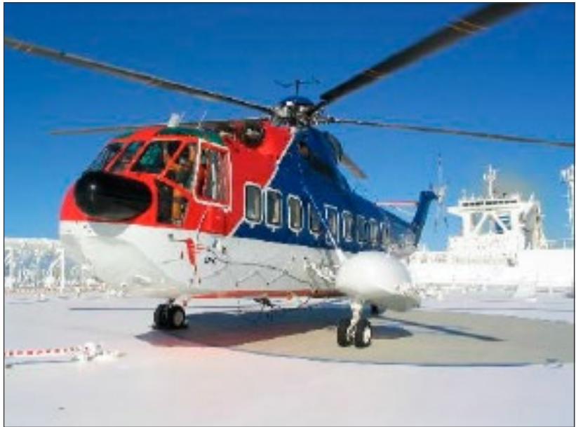
Figure I-5-1. S61N operating to a non-purpose-built ship’s side heliport
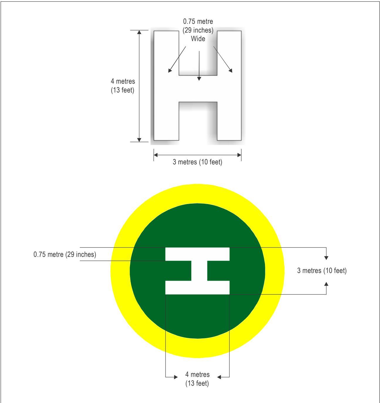
Figure I-5-2. Dimensions of the heliport identification “H” marking (standard size)
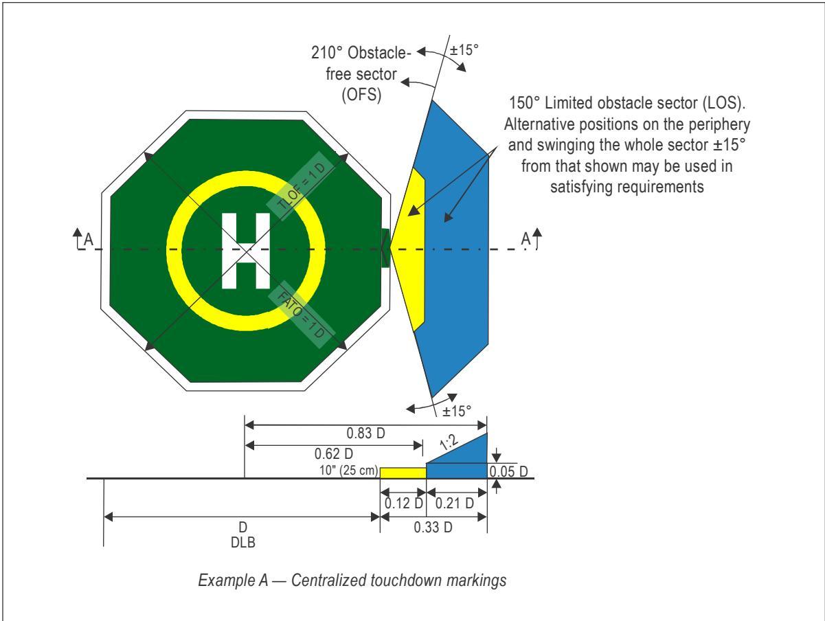
Figure I-5-3. Location of touchdown markings (Example A)
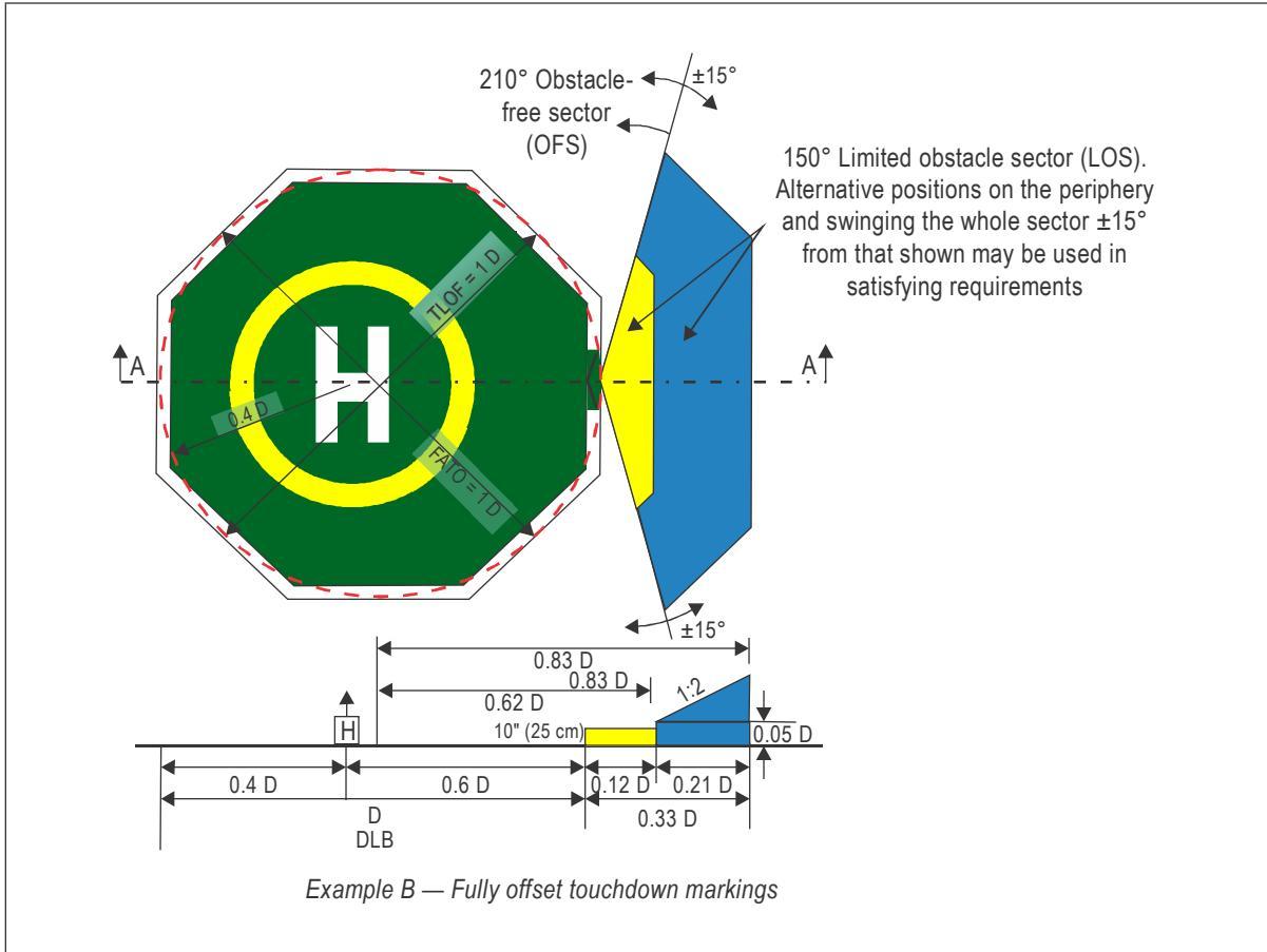
Figure I-5-3. Location of touchdown markings (Example B)
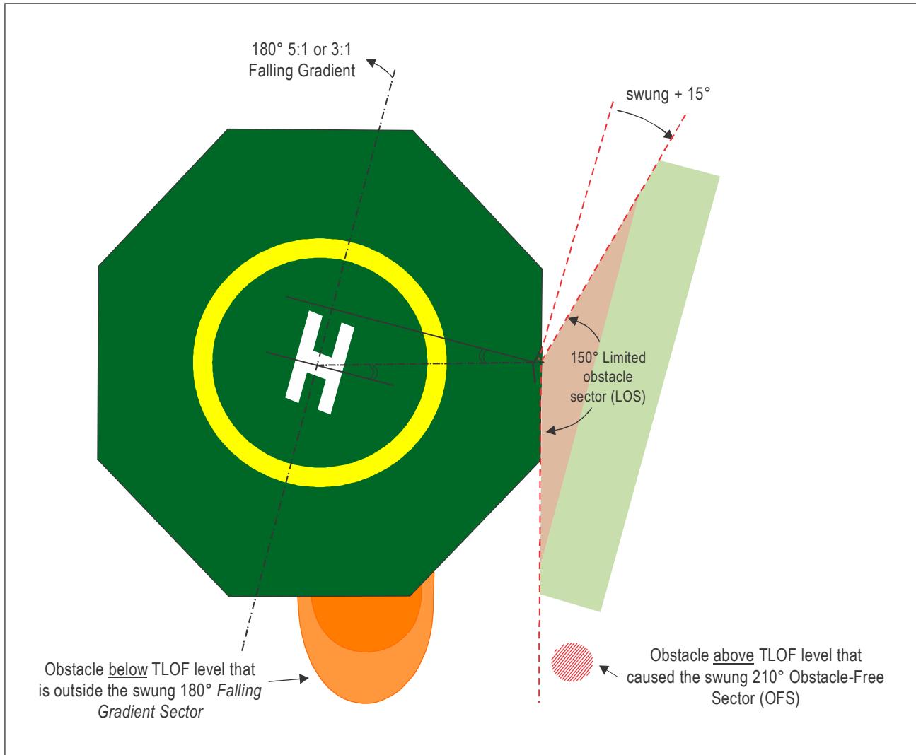
Figure I-5-4. Heliport identification marking reflecting a swung OFS (in this case the OFS is swung by 15 degrees in a clockwise direction to avoid an obstacle)
Note 1.— The bisector of the 210° obstacle-free sector (OFS) should normally pass through the Centre of the D-circle. The sector may be ‘swung’ by up to 15° in either direction from the normal. (A 15° clockwise swing is illustrated).
Note 2.— If the 210° OFS is swung, then it would be normal practice to swing the 180° falling 5:1 gradient by a corresponding amount to indicate, and align with, the swung OFS.
Part I. Offshore heliports Chapter 5. Visual aids — Marking and lighting
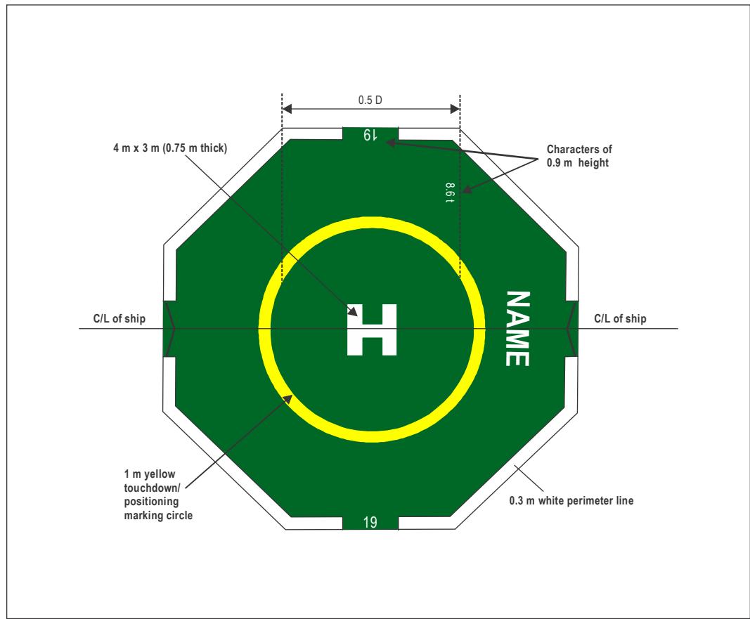
Figure I-5-5. D-value markings for a purpose-built shipboard heliport in an amidships location
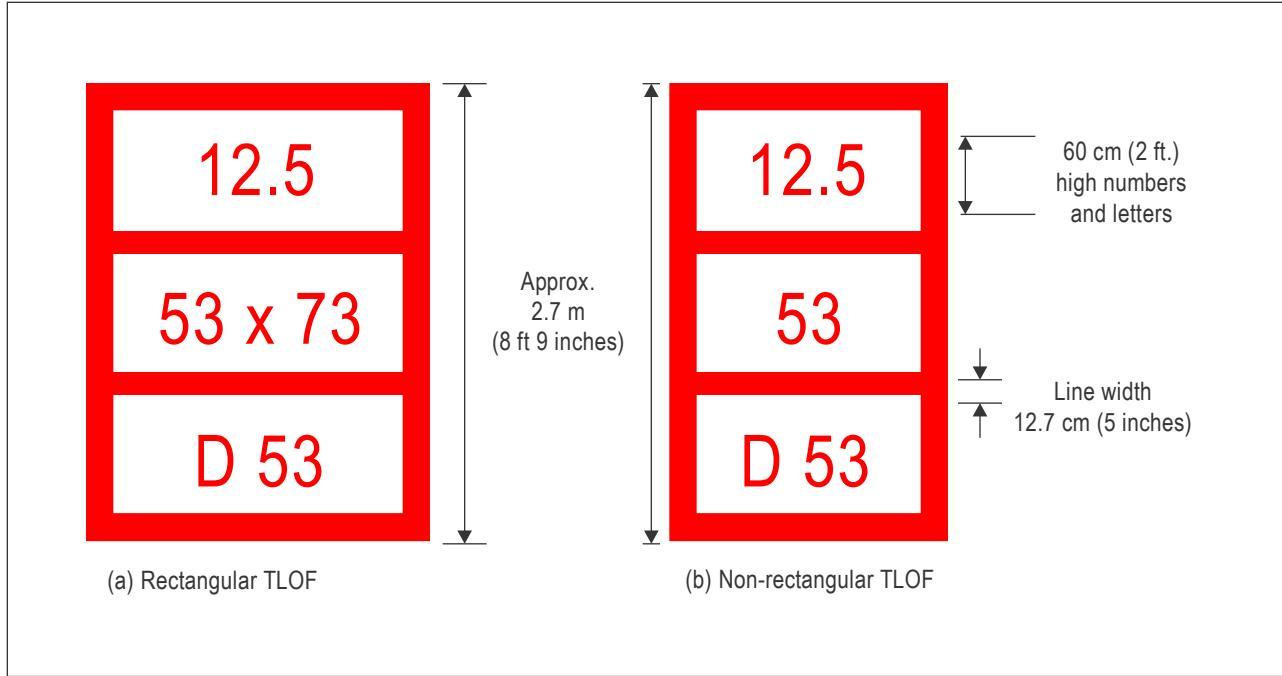
Figure I-5-5A. Helideck limitation markings — imperial units
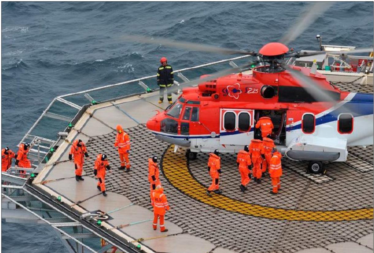
Figure I-5-6. Accurate positioning of a helicopter by correct use of the touchdown/positioning marking (TD/PM) circle
Part I. Offshore heliports Chapter 5. Visual aids — Marking and lighting
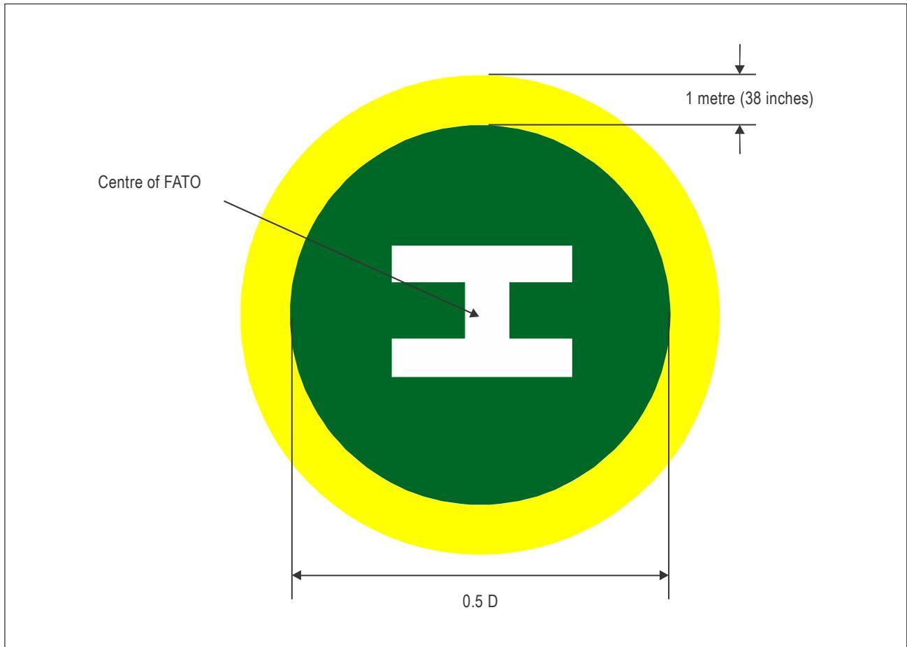
Figure I-5-7. Touchdown/positioning marking circle (painted yellow)
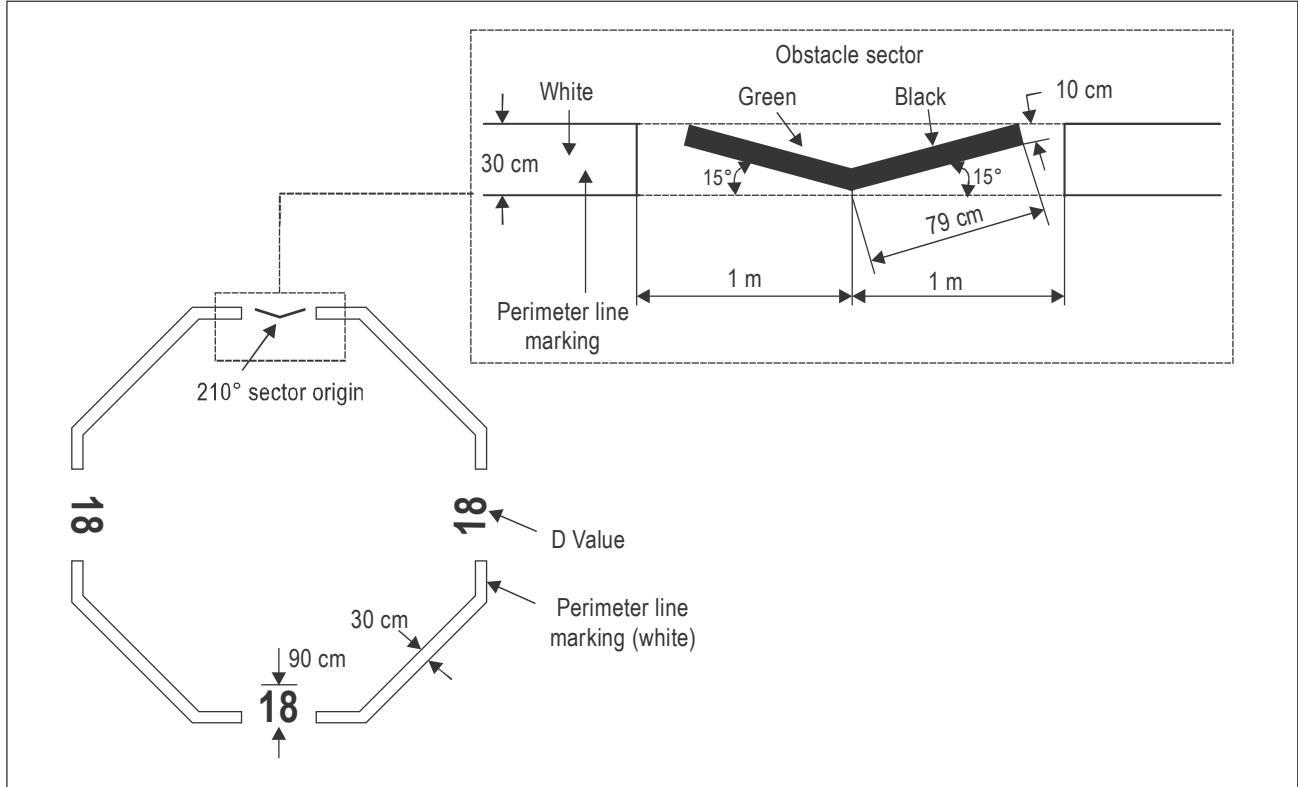
Figure I-5-8. Chevron for a 1 D helideck and helideck D-value markings
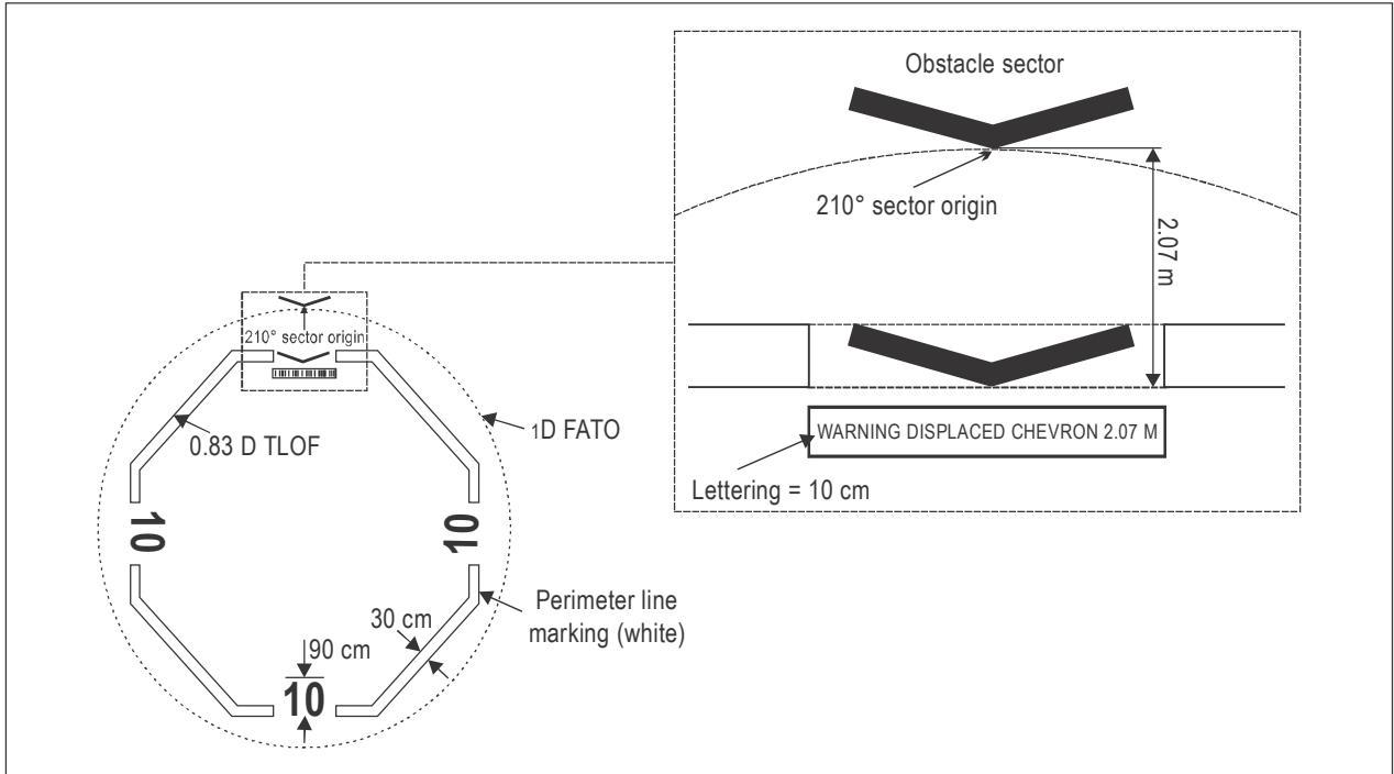
Figure I-5-9. Chevron for a 0.83 D helideck
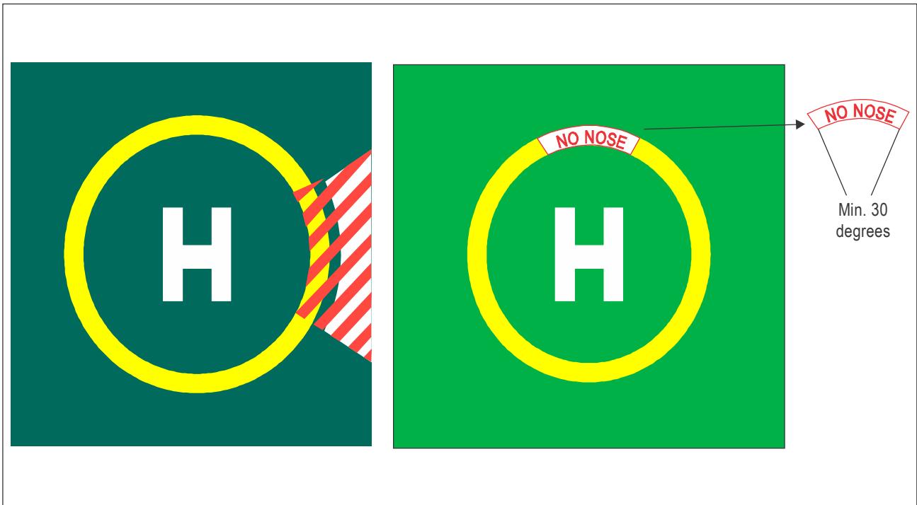
Figure I-5-10. Examples of an alternative prohibited landing sector (PLS) marking
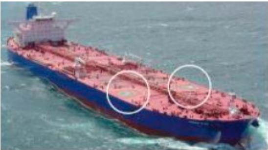
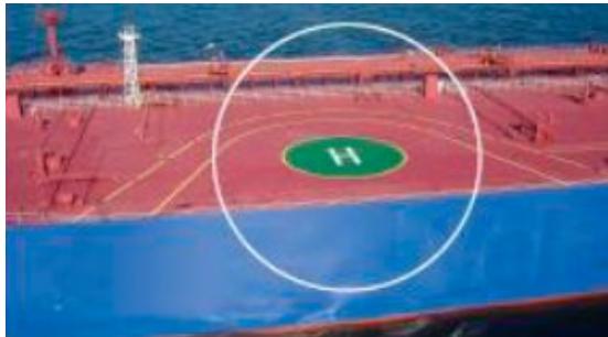
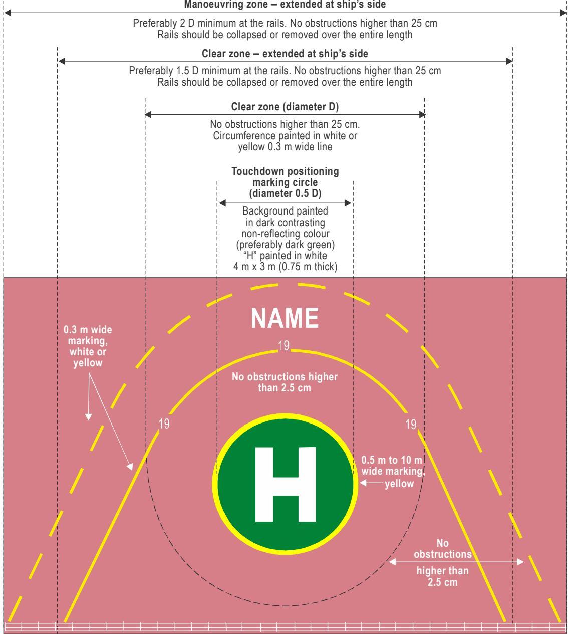
Figure I-5-11. Heliport markings — special considerations for non-purpose-built shipboard heliports
Part I. Offshore heliports Chapter 5. Visual aids — Marking and lighting
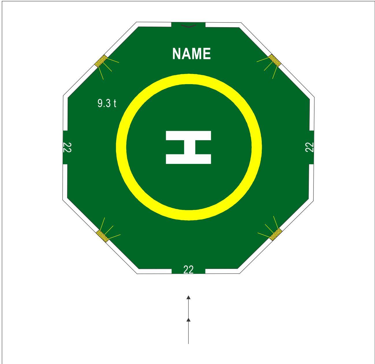
Figure I-5-12. Typical floodlighting arrangement for an octagonal helideck
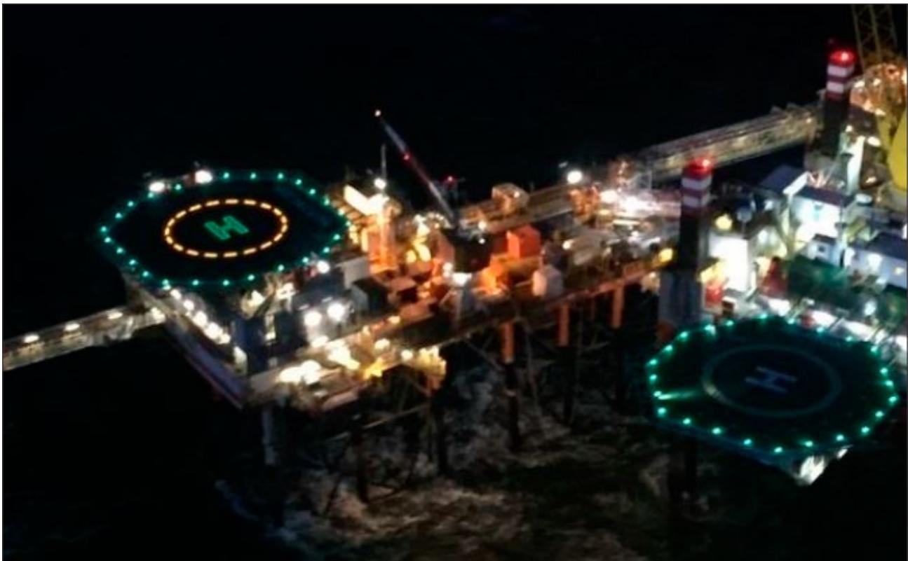
Figure I-5-13. Fixed platform (left) with the lit TD/PM and the lit heliport identification marking scheme. Mobile offshore drilling unit (right) with deck-mounted floodlighting system
Part I. Offshore heliports Chapter 5. Visual aids — Marking and lighting
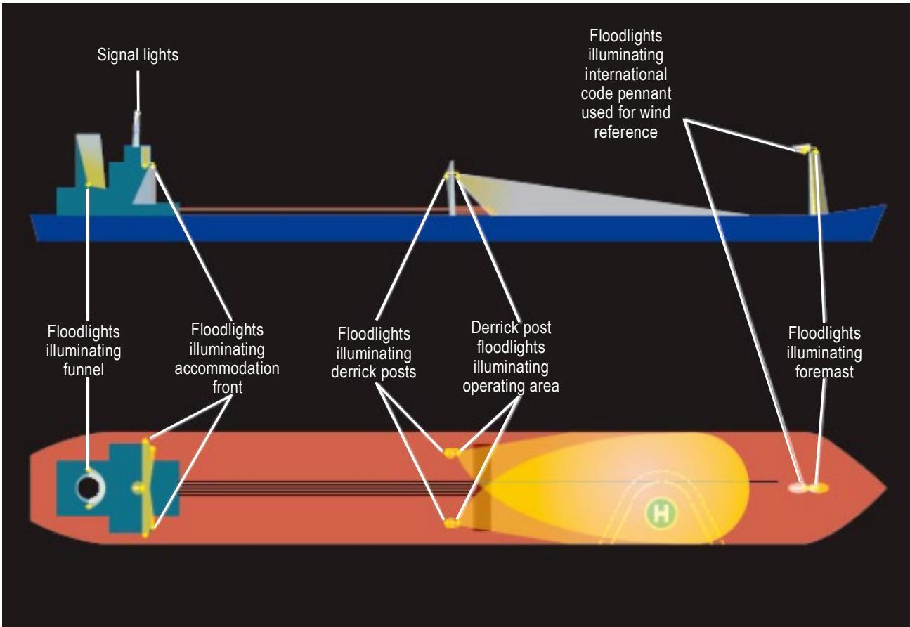
Figure I-5-14. Lighting systems — special considerations for non-purpose-built shipboard heliports
Chapter 6
HELIDECK RESCUE AND FIREFIGHTING FACILITIES
6.1 INTRODUCTION
6.1.1 This chapter provides guidance regarding the provision of equipment, extinguishing media, personnel, training, and emergency procedures for offshore helidecks and should be read in conjunction with the guidance material presented in this manual, to support Annex 14, Volume II, Section 6.2 Rescue and Firefighting. Unless specifically stated, it should be assumed that all sections apply to an offshore facility regardless of the manning policy (i.e. whether a permanently attended installation (PAI) or a not permanently attended installation (NPAI)). For editorial convenience, when it fits the context, the generic term “landing area” is used and may be assumed to include both attendance models (PAIs and NPAIs) for fixed offshore heliports.
6.1.2 Rescue and firefighting (RFF) requirements for purpose-built shipboard heliports on ships constructed before 1 January 2020 should at least comply with paragraphs 5.1.3 to 5.1.5 of SOLAS regulation II-2/18 and, for ships constructed on or after 1 January 2020, with the provisions of Chapter 17 of the Fire Safety Systems Code. For non-purpose-built shipboard heliports on ships constructed before 1 January 2020, RFF arrangements should at least be in accordance with Part C of SOLAS II-2, Helicopter Facilities, and for ships constructed on or after 1 January 2020, with the relevant provisions of Chapter 17 of the Fire Safety Systems Code. It may therefore be assumed that this chapter does not include RFF arrangements for purpose-built or non-purpose-built heliports or for shipboard winching areas.
6.1.3 The principal objective of an RFF response is to save lives. For this reason, the provision of a means of dealing with a helicopter accident or incident occurring at or in the immediate vicinity of the landing area assumes primary importance because it is within this area that there are the greatest opportunities for saving lives. This should assume at all times the possibility of, and need for, bringing under control and then extinguishing a fire which may occur either immediately following a helicopter accident or incident (e.g. crash and burn) or at any time during rescue operations.
6.1.4 The most important factors having a bearing on effective rescue in a survivable helicopter accident are the speed of initiating a response and the effectiveness of that response. Requirements to protect accommodation beneath or in the vicinity of the landing area, a fuel installation (where provided) or the support structure of the offshore heliport are not taken into account in this chapter, nor are any additional considerations that may arise from the presence of a second helicopter located in a parking area (see Chapter 8). In the case of a parking area, consideration may be given for providing a passive fire-retarding surface supplemented with hand-held extinguishers.
6.1.5 Due to the nature of offshore operations, usually taking place over large areas of open sea, an assessment will need to be carried out to determine if specialist rescue services and firefighting equipment are needed to mitigate the additional risks and specific hazards of operating over open sea areas. These considerations will form a part of the heliport emergency plan.
6.2 KEY DESIGN CHARACTERISTICS — PRINCIPAL AGENT
6.2.1 A key aspect in the successful design for providing an efficient, integrated rescue and firefighting facility is a complete understanding of the circumstances in which it may be expected to operate. A helicopter accident which results in a fuel spillage with wreckage and/or fire and smoke has the capability to render some of the equipment inventory unusable or to preclude the use of some passenger escape routes.
6.2.2 Delivery of firefighting media to the landing area at the appropriate application rate should be achieved in the quickest possible time. The method for delivery of the primary agent is best achieved through a fixed foam application system (FFAS) with an automatic or semi-automatic method used for the distribution of extinguishing agent to knock down and bring a fire under control in the shortest possible time, while protecting the means of escape for personnel to quickly and easily alight clear of the landing area to a place of safety. An FFAS may include, but is not necessarily limited to: a fixed monitor system (FMS), a deck integrated firefighting system (DIFFS), or, for a helideck with a D-value of 20 m (65.6 ft) or less, a ring main system (RMS). The purpose of this chapter is to discuss in detail the specification for an FMS and, as the alternative means of compliance, the preferred method of delivery now widely used in the offshore sector; a DIFFS. The specification for an RMS, or any other alternative means of compliance present or future, is not discussed in detail in this chapter. However, the critical area calculations illustrated in Section 6.2.8.1 are the recommended minimum objectives for any FFAS. An FMS, RMS or DIFFS should therefore be regarded as different methods by which the uniform distribution of foam, at the required application rate and for the required duration, may be efficiently distributed to the whole of the landing area (an area that is based on the D-circle of the critical design helicopter). For an FMS, where, due to its location around the periphery of the helideck, a good range of application is essential, foam is initially applied in a solid stream (jet) application. A dispersed pattern is applied through a DIFFS or an RMS where the requirement is to deliver media at shorter ranges to combine greater coverage and a more effective surface application of primary media. Where a solid plate helideck is provided, i.e. a helideck having a solid plate surface design set to a fall or camber which allows fuel to drain across the solid surface into a suitable drainage collection system, primary media will always consist of foam (see Note below and Section 6.2.8). However, where the option is taken to install a passive fire-retarding surface constructed in the form of a perforated surface or grating which contains numerous holes that allow burning fuel to rapidly drain through the surface of the helideck, the use of water in lieu of foam is accepted. Where water is used the critical area calculation applicable for Performance Level C foam is applied (see Section 6.2.8).
Note.— From time to time, new technologies may come to market which, providing they are demonstrated by rigorous testing to be at least as effective as solutions described elsewhere in this chapter, with the approval of the appropriate authority, may be considered for helideck firefighting. For example, compressed air foam systems (CAFS) may be considered, with foam distributed through a DIFFS. CAFS has the ability to inject compressed air into foam to generate an effective solution to attack and suppress a helideck fire. This type of foam has a tighter, denser bubble structure than standard foams, which allows it to penetrate deeper into the fire before the bubbles are broken down. CAFS is able to address all sides of the fire triangle by smothering the fire (preventing oxygen from combining with the fuel), by diminishing the heat, using trapped air within the bubble structure, and by disrupting the chemical reaction required for a fire to continue. Hence the application rate for a DIFFS using Performance Level B compressed air foam may be accordingly reduced — see calculation of application rate in Section 6.2.8.
6.2.3 Given that the effectiveness of any FFAS is the speed of initiating a response in addition to the effectiveness of that response, it is recommended that a delay of less than 15 seconds, measured from the time the system is activated to actual production at the required application rate, should be the objective. The operational objective of an FFAS should ensure that the system is able to bring under control a helideck fire associated with a crashed helicopter within 1 minute measured from the time the system is activated and producing foam at the required application rate for the range of weather conditions prevalent for the helicopter operating environment.
Note.— A fire is deemed to be under control at the point when the initial intensity of the fire is reduced by 90 per cent.
6.2.4 An FFAS should be of adequate performance and be suitably located to ensure an effective application of foam to any part of the landing area irrespective of the wind strength/direction or accident location when all components of the system are operating in accordance with the manufacturer’s technical specifications for the equipment. However, for an FMS, consideration should also be given to the loss of a (downwind) foam monitor either due to limiting weather conditions or as a result of a crash situation occurring. The design specification for an FMS (usually consisting of 2, 3 or 4 fixed monitors) should ensure remaining monitor(s) are capable of delivering finished foam to the landing area at or above the minimum application rate. For areas of the landing area or its appendages which, for any reason, may be otherwise inaccessible to an FMS, it is necessary to provide additional hand controlled foam branch pipes as described further below.
6.2.5 Consideration should be given to the effects of the weather on static equipment. All equipment forming part of the RFF response should be designed to withstand protracted exposure to the elements or be protected from them. Where protection is the chosen option, it should not prevent the equipment being brought into use quickly and effectively (see paragraphs above). The effects of condensation on stored equipment should be considered.
6.2.6 The minimum capacity of the fixed foam application system will depend on the D-value of the design helicopter, the required foam application rate at the helideck, the discharge rates of installed equipment (i.e. capacity of main fire pump) and the expected duration of application. It is important to ensure that the capacity of the main offshore heliport fire pump is sufficient to guarantee that finished foam can be applied at the appropriate induction ratio and application rate and for the minimum duration to the whole of the landing area, when all monitors are being discharged simultaneously.
6.2.7 The application rate is dependent on the types of foam concentrate in use and the types of foam application equipment selected. For fires involving aviation kerosene, ICAO has produced a performance test which assesses and categorizes the foam concentrate. Foam concentrate manufacturers will be able to advise on the performance of their concentrates against these tests. It is recommended that foam concentrates compatible with seawater and meeting at least performance level ‘B’ or performance level ‘C’ are used. Level ‘B’ foams should be applied at a minimum application rate of 5.5 litres per square metre per minute. Level ‘C’ foams should be applied at a minimum application rate of 3.75 litres per square metre per minute. Where seawater is used in lieu of foam (see Section 6.2.2) the application rate should be the same as for performance level ‘C’ foam.
6.2.8 Calculation of the application rate
6.2.8.1 Example based on the D-circle for an S92 (for the purpose of illustration assumed to be the design helicopter with a D = 20.88):
For a performance level B foam:
$$ \mathsf { A p p l i c a t i o n ~ r a t e = 5 . 5 \times \pi \times r ^ { 2 } \left( 5 . 5 \times 3 . 1 4 2 \times 1 0 . 4 4 \times 1 0 . 4 4 \right) = 1 8 8 3 \mathrm { ~ l i t r e s ~ p e r ~ m i n u t e } } $$
For a performance level C foam (or seawater):
Application rate = 3.75 x π x r2 (3.75 x 3.142 x 10.44 x 10.44) = 1 284 litres per minute
For a performance level B compressed air foam:
$$ \mathsf { A p p l i c a t i o n \ r a t e = 3 . 0 0 \times \pi } \times \mathsf { r ^ { 2 } } ( 3 . 0 0 \times 3 . 1 4 2 \times 1 0 . 4 4 \times 1 0 . 4 4 ) = 1 \ 0 2 7 \ | \mathsf { i t r e s \ p e r \ m i n u t e } $$
6.2.8.2 Given the often remote location of offshore heliports, the overall capacity of the foam system should exceed that which is necessary for the initial suppression and extinction of the fire. Five minutes of foam application capability for a solid plate helideck is generally considered to be reasonable. In the case of a passive fire-retarding surface with a wateronly DIFFS the discharge duration may be reduced to no less than three minutes.
6.2.9 Calculation of minimum operational stocks
6.2.9.1 Using the 20.88 m example as shown in Section 6.2.8.1 above, a 1 per cent performance level ‘B’ foam solution discharged over five minutes at the minimum application rate will require: 1 $\mid 8 8 3 \times 0 . 0 1 \times 5 = 9 4$ litres of foam concentrate.
6.2.9.2 A 3 per cent performance level ‘C’ foam solution discharged over five minutes at the minimum application rate will require 1 284 x 0.03 x 5 = 193 litres of foam concentrate
Note.— Sufficient reserve foam stocks to allow for replenishment as a result of operation of the system during an incident or following training or testing, will also need to be considered.
6.2.10 Low expansion foam concentrates can generally be applied in either aspirated or non-aspirated form. It should be recognized that while non-aspirated foam may provide a quick knockdown of any fuel fire, aspiration, i.e. the induction of air into the foam solution discharged by monitor or by hand controlled foam branch (see below), gives enhanced protection after extinguishment. Wherever a non-aspirated FFAS is selected during design, additional hose lines capable of producing aspirated foam for post-fire security/control should be provided on solid-plate helidecks.
6.2.11 Not all fires are capable of being accessed by monitors, and in some scenarios their use may actually endanger passengers. Therefore, in addition to foam monitor systems, there should be the ability to deploy at least two deliveries with hand controlled foam branch pipes for the application of aspirated foam at a minimum rate of 225 to 250 litres/minute through each hose line. A single hose line, capable of delivering aspirated foam at a minimum application rate of 225 to 250 litres/minute, may be acceptable where it is demonstrated that the hose line is of sufficient length, and the hydrant system of sufficient operating pressure, to ensure the effective application of foam to any part of the landing area irrespective of wind strength or direction. The hose line(s) provided should be capable of being fitted with a branch pipe able to apply water in the form of a jet or spray pattern for cooling, or for other specific firefighting tactics.
6.2.12 As an effective alternative means of compliance to an FMS, offshore heliports are encouraged to consider the provision of a DIFFS. These systems typically consist of a series of pop-up nozzles with both a horizontal and vertical component, designed to provide an effective spray distribution of foam to the whole of the landing area and protection for the helicopter suitable for a range of weather conditions. A DIFFS on a solid-plate helideck should be capable of supplying performance level ‘B’ or level ‘C’ foam solution to bring under control a fire associated with a crashed helicopter within the time constraints stated in Section 6.2.3 achieving an average (theoretical) application rate over the entire landing area (based on the D-circle) of 5.5 litres per square metre per minute for performance level ‘B’ foams and 3.75 litres per square metre per minute for performance level ‘C’ foams, for a duration which at least meets the minimum requirements stated in Section 6.2.8.2 above.
6.2.13 When an FFAS consisting of a DIFFS capable of delivering foam and/or seawater in a spray pattern to the whole of the landing area (see previous paragraphs and Note below) is selected in lieu of an FMS, full scale testing has confirmed that the provision of additional hand-controlled foam branch pipes may not be necessary to address any residual fire situation. Instead any residual fire may be tackled with the use of hand-held extinguishers (see Chapter 4).
6.2.14 The precise number and lay out of pop-up nozzles will be dependent on the specific landing area design, particularly the dimensions of the landing area. However, nozzles should not be located adjacent to helideck egress points as this may hamper quick access to the helideck by trained rescue crews and/or impede occupants of the helicopter from escaping to a safe place away from the landing area. Notwithstanding this, the number and layout of nozzles should be sufficient to provide an effective spray distribution of foam over the entire landing area with a suitable overlap of the horizontal spray component from each nozzle, assuming calm wind conditions. It is recognized in meeting the objective for the average (theoretical) application rate specified above for performance level ‘B’ or level ‘C’ foams that there may be some parts of the landing area, particularly where the spray pattern of nozzles significantly overlap, where the average (theoretical) application rate is exceeded in practice. Conversely, for other areas the application rate in practice may fall slightly below the average (theoretical) application rate specified in Section 6.2.12. This is acceptable provided that the actual application rate achieved for any portion of the landing area does not fall below two-thirds of the application rates specified.
Note.— Where a DIFFS is used in tandem with a passive fire-retarding system demonstrated to be capable of removing significant quantities of unburned fuel from the surface of the offshore heliport, in the event of a fuel spill from a ruptured aircraft tank, it is permitted to select a seawater-only DIFFS to deal with any residual fuel burn. A seawater-only
DIFFS should meet the same application rate as specified for a performance level ‘C’ foam DIFFS in Section 6.2.12 and duration as specified in Section 6.2.8.2. (See also Section 6.5 for not permanently attended installations (NPAIs).)
6.2.15 In a similar way to where an FMS is provided, the performance specification for a DIFFS needs to consider the likelihood that one or more of the pop-up nozzles may be rendered ineffective by the impact of a helicopter on the deck surface. Any local damage to the DIFFS nozzles and distribution system, caused by a helicopter crash, should not hinder the system’s overall ability to deal effectively with a fire situation. To this end, a DIFFS supplier should be able to verify that a system where at least one of the nozzles is rendered inactive remains fit-for-purpose, and is able to bring a fire associated with a crashed helicopter under control within one minute measured from the time the system is producing foam at the required application rate.
6.2.16 A variation on the basic design performance level ‘B’ or level ‘C’ foam DIFFS is a DIFFS CAFS (see the Note below Section 6.2.2).
6.2.17 If lifesaving opportunities are to be maximized, it is essential that all equipment should be ready for immediate use on, or in the immediate vicinity of, the landing area whenever helicopter operations are being conducted. All equipment should be located at points having immediate access to the landing area. The location of the storage facilities should be clearly indicated.
6.3 USE AND MAINTENANCE OF FOAM EQUIPMENT
6.3.1 Mixing different concentrates in the same tank, i.e. different either in make or strength, is generally unacceptable. Many different strengths of concentrate are on the market, but the most common concentrates found offshore are 1 per cent, 3 per cent or 6 per cent. Any decision regarding selection should take into account the design characteristics of the foam system. It is important to ensure that foam containers and tanks are correctly labelled.
6.3.2 Induction equipment ensures that water and foam concentrate are mixed in the correct proportions. The settings of adjustable inductors, if installed, should correspond with the strength of concentrate in use.
6.3.3 All parts of the foam production system, including the finished foam, should be tested by qualified personnel upon commissioning and annually thereafter. The tests should assess the performance of the system against original design expectations while ensuring compliance with any relevant pollution regulations.
6.4 COMPLEMENTARY MEDIA
6.4.1 While foam is considered the principal agent for dealing with fires involving fuel spillages, the wide variety of fire incidents likely to be encountered during offshore helicopter operations — e.g. engine, avionic bays, transmission areas, hydraulics — may require the provision of more than one type of complementary agent. Dry powder and gaseous agents are generally considered acceptable for this task. The complementary agents selected should comply with the appropriate specifications of the International Organization for Standardization (ISO). Systems should be capable of delivering the agents through equipment which will ensure its effective application.
Note.— Halon extinguishing agents are no longer specified for new installations. Gaseous agents, including $C O _ { 2 } ,$ have replaced them. The effectiveness of $C O _ { 2 }$ is accepted as being half that of Halon.
6.4.2 Dry chemical powder is recommended as the primary complementary agent. For helidecks up to and including 16 m (52.5 ft) the minimum total capacity should be 23 kg (50 lbs) delivered from one or two extinguishers. For helidecks above 16 m (52.5 ft) and up to 24 m (78 ft), the minimum total capacity should be 45 kg (99 lbs) delivered from one, two or three extinguishers. For helidecks above 24 m (78 ft) the minimum total capacity should be 90 kg (198 lbs) delivered from two, three or four extinguishers. The dry powder system should have the capability to deliver the agent anywhere on the landing area and the discharge rate of the agent should be selected for optimum effectiveness of the agent. Containers of sufficient capacity to allow continuous and sufficient application of the agent should be provided.
6.4.3 A quantity of gaseous agent is recommended in addition to the use of dry powder as a secondary complementary agent. A quantity of gaseous agent should be provided with a suitable applicator for use on engine fires. The appropriate minimum quantity delivered from one or two extinguishers is 9 kg (19 lbs) for helidecks up to and including 16.00 m (52.5 ft), 18 kg (39 lbs) for helidecks above 16.00 m (52.5 ft) and up to 24.00 m (78 ft), and 36 kg (78 lbs) for helidecks above 24.00 m (78 ft). The discharge rate should be selected for optimum effectiveness of the agent. Due regard should be given to the requirement to deliver gaseous agents to the seat of the fire at the recommended discharge rate. Due to the windy conditions prevalent in many offshore sectors, complementary agents may be adversely affected during application and if considering gaseous media the ambient conditions should be taken into account.
6.4.4 Offshore helicopters have integral engine fire protection systems (predominantly Halon) and it is therefore considered that the provision of foam as the principal agent, plus suitable water/foam branch lines, plus sufficient levels of dry powder with a quantity of secondary gaseous agent, will form the core of the fire extinguishing system. It should be noted that none of the complementary agents listed will offer any post-fire security/control.
6.4.5 All applicators are to be fitted with a mechanism which allows them to be hand-controlled.
6.4.6 Dry chemical powder should be of the foam-type compatible.
6.4.7 The complementary agents should be sited so that they are readily available at all times.
6.4.8 Reserve stocks of complementary media to allow for replenishment as a result of activation of the system during an incident, or following training or testing, should be held.
6.4.9 Complementary agents should be subject to annual visual inspection by qualified personnel and pressure tested in accordance with manufacturers’ recommendations.
6.5 NOT PERMANENTLY ATTENDED INSTALLATIONS (NPAI)
6.5.1 In the case of NPAIs, where RFF equipment will be unattended during certain helicopter movements, the application of foam through a manually operated fixed monitor system is not recommended. For installations which are at times unattended, the effective delivery of foam to the whole of the landing area is best achieved by means of a fullyautomated DIFFS. See Sections 6.2.12 to 6.2.15 for specification.
6.5.2 For NPAIs, other combination solutions where these can be demonstrated to be effective in dealing with a running fuel fire may be considered. This could permit, for example, the selection of a seawater-only DIFFS used in tandem with a passive fire-retarding system demonstrated to be capable of removing significant quantities of unburned fuel from the surface of the landing area in the event of a fuel spill from a ruptured aircraft tank. In this case the minimum discharge duration should meet the appropriate requirements specified in Section 6.2.8.2.
6.5.3 DIFFS on NPAIs should be integrated with platform safety systems such that pop-up nozzles are activated automatically in the event of an impact of a helicopter where a post-crash fire (PCF) results. The overall design of a DIFFS should incorporate a method of fire detection and be configured to avoid spurious activation and should be capable of manual override. Similar to a DIFFS provided for a PAI, a DIFFS provided on an NPAI needs to consider the eventuality that one or more nozzles may be rendered ineffective by, for example, a crash. The basic performance assumptions stated in Section 6.2.12 to 6.2.15 should also apply for a DIFFS located on an NPAI.
6.6 THE MANAGEMENT OF EXTINGUISHING MEDIA STOCKS
6.6.1 Consignments of extinguishing media should be used in delivery order to prevent deterioration in quality by prolonged storage.
6.6.2 The mixing of different types of foam concentrate may cause serious density issues and result in the possible malfunctioning of foam production systems. Unless evidence is given to the contrary, it should be assumed that different types are incompatible. In the event of mixing it is essential that the tank(s), pipe work and pump (if fitted) are thoroughly cleaned and flushed prior to the new concentrate being introduced.
6.6.3 Consideration should be given to the provision of reserve stocks for use in training, testing and recovery from emergency use.
6.7 RESCUE EQUIPMENT
6.7.1 In some circumstances, lives may be lost if simple ancillary rescue equipment is not readily available.
6.7.2 The provision of minimum equipment is recommended as listed in Table I-6-1. Sizes of equipment are not detailed in this table, but should be appropriate for the types of helicopter expected to use the facility.
6.7.3 Appropriate personnel should be appointed to ensure that the rescue equipment is checked and maintained regularly.
6.7.4 Rescue equipment should be stored in clearly marked and secure watertight cabinets or chests. An inventory checklist of equipment should be held inside each equipment cabinet/chest.
6.8 PERSONNEL LEVELS
6.8.1 The facility or vessel should have a sufficient number of trained firefighting personnel immediately available whenever helicopter movements are taking place. A determination of what constitutes sufficient resources may be made on a case-by-case basis by use of a task resource analysis. When conducting this assessment, it is recommended that the following be taken into account, at minimum:
a) helicopter types using the helideck, including maximum passenger seating configuration, composition, fuel loads (and whether fuel can be uplifted on site);
b) expectations for the rescue of helicopter occupants, e.g. assisted rescue model;
c) design and complexity of the firefighting arrangements, e.g. equipment to address worst case PCF with rescue of occupants; and
d) availability of additional emergency support personnel to assist dedicated helideck personnel.
6.8.2 Dedicated helideck personnel should be deployed to allow the appropriate, efficient operations of firefighting and rescue systems and to maximum advantage, so that any helideck incident can be managed effectively. The helicopter landing officer (HLO) should be readily identifiable to the helicopter crew as the person in charge of operations. The preferred method of identification is a brightly coloured ‘HLO’ tabard/waistcoat.
6.9 PERSONAL PROTECTIVE EQUIPMENT (PPE)
6.9.1 All responding RFF personnel should be provided with appropriate personal protective equipment (PPE) and respiratory protective equipment (RPE) to allow them to carry out their duties in an effective manner.
6.9.2 Sufficient personnel to operate the RFF equipment effectively should be dressed in protective clothing prior to helicopter movements taking place. In addition, equipment should only be used by personnel who have received adequate information, instruction and training. PPE should be accompanied by suitable safety measures e.g. protective devices, markings and warnings. The specifications for PPE should meet one of the following international standards:
| NFPA | EN | BS | |
| Helmet with visor | NFPA 1971 | EN443 | BS EN 443 |
| Gloves | NFPA 1971 | EN659 | BSEN 659 |
| Boots (footwear) | NFPA 1971 | EN ISO 20345 | BS EN ISO 20345 |
| Tunic and trousers | NFPA 1971 | EN469 | BS EN ISO 14116 |
| Flash-hood | NFPA 1971 | EN13911 | BS EN 13911 |
6.9.3 Appropriate personnel should be appointed to ensure that all PPE is installed, stored, used, checked and maintained in accordance with the manufacturer’s instructions. Facilities should be provided for the cleaning, drying and storage of PPE when crews are off duty. Facilities should be well-ventilated and secure.
6.9.4 In addition, equipment should only be used by personnel who have received adequate information, instruction and training. PPE should be accompanied by suitable safety measures e.g. protective devices, markings and warnings. Appropriate PPE is included in Table I-6-1. Specific outcomes from the task-resource analysis may determine a requirement for additional PPE, or that, given the specific rescue model employed, certain items may not be required.
6.10 TRAINING
6.10.1 If they are to effectively utilize the equipment provided, all personnel assigned to RFF duties on the landing area should be fully trained to carry out their duties to ensure competence in role and task. It is recommended that personnel attend an established helicopter firefighting course.
6.10.2 In addition, regular recurrent training in the use of all RFF equipment, helicopter type familiarization and rescue tactics and techniques should be carried out. Correct selection and use of principal and complementary media for specific types of incident should form an integral part of personnel training.
6.11 EMERGENCY PROCEDURES
6.11.1 The heliport emergency plan should specify the actions to be taken in the event of an emergency involving a helicopter on or near the installation or vessel. The heliport emergency plan sets out the procedures for coordinating the response of agencies or services that could be of assistance in responding to an emergency at an offshore heliport.
6.11.2 Details of the scope and content for heliport emergency planning are addressed in detail in Annex 14, Volume II, Chapter 6, 6.1.
Table I-6-1. Rescue equipment
| Adjustable wrench | 1 |
| Rescue axe, large (non-wedge or aircraft type) | 1 |
| Cutters, bolt | 1 |
| Crowbar, large | 1 |
| Hook, grab or salving | 1 |
| Hacksaw (heavy duty) and six spare blades | 1 |
| Blanket, fire resistant | 1 |
| Ladder (two-piece)* | 1 |
| Life line (5 mm circumference × 15 m in length) plus rescue harness | 1 |
| Pliers, side cutting (tin snips) | 1 |
| Set of assorted screwdrivers | 1 |
| Harness knife and sheath or harness cutters** | ** |
| Man-made mineral fibre (MMMF) filter masks** | ** |
| Gloves, fire resistant** | ** |
| Power cutting too*** | 1 |
* For access to casualties in an aircraft on its side.
** This equipment is required for each helideck crew member.
*** Requires additional approved training by competent personnel only specified for helicopters above 24 m (78 ft).
Chapter 7
WINCHING AREAS ON SHIPS
7.1 GENERAL CONSIDERATIONS INCLUDING LOCATION, PHYSICAL CHARACTERISTICS AND OBSTACLE PROTECTION
Note.— The proposed application of this chapter is to winching areas located on ships. However, States may seek to apply the basic same criteria, but with some alleviations, for heli-hoist activities that occur, where permitted, on fixed platforms, e.g. for a winching area located on an offshore support substation. Applying the same criteria provides an additional degree of conservatism as fixed platforms are not subject to the same effects of motion that occur on ships (the amount of heave, sway or surge motion can vary considerably depending on the location of the winching area on a ship – see Chapter 3, 3.2.5.3). Therefore, for winching areas located on fixed platforms, some relaxation of the clear zone dimension (see Section 7.1.3) and the manoeuvring zone (see Section 7.1.4) may be considered by the appropriate authority.
7.1.1 Where practicable, the helicopter should always land rather than winch (an operation commonly referred to as helicopter hoist operation (HHO)) because safety is enhanced when the time spent hovering is reduced. However, certain types of ships, which need to engage helicopter support but are unable to provide the space and/or obstacle limitation surfaces needed to meet the requirements for a shipboard heliport, may need to consider a shipboard winching area in lieu of a shipboard heliport landing area.
7.1.2 The optimum position for a winching area will be determined primarily by the availability of a suitable space on the ship. However, a winching operation should be located over an area to which the helicopter can safely hover while winching to or from the ship. Its location should allow the pilot an unimpeded view of the whole of the winching area clear zone and the ship’s topside layout. Where more than one area capable of accommodating a winching area exists, preference should be given to the location that best minimizes aerodynamic and wave motion effects. In addition, the winching area should preferably be clear of accommodation spaces and provide adequate deck areas adjacent to the manoeuvring zone to allow for safe access to the winching area from at least two different directions. In selecting a suitable winching area, the desirability for keeping the winching (hoist) height to a minimum should also be borne in mind, such that the area chosen will allow a helicopter to hover at a safe height above the highest obstacle that may be present in the manoeuvring zone.
7.1.3 The winching area clear zone should comprise a circular area with a minimum diameter of 5 m (16 ft). This clear zone should be a solid surface capable of accommodating personnel and/or stores for which the winching area is intended. In addition the clear zone should be entirely obstacle-free.
7.1.4 The manoeuvring zone, divided into an inner and outer area, should encompass and extend beyond the clear zone to a minimum overall diameter of 2 D. The inner manoeuvring zone, having a diameter of not more than 1.5 D, may contain objects which are no higher than 3 m (9 ft) above the surface of the clear zone, while the outer manoeuvring zone, having an overall diameter of at least 2 D, may contain objects that are no higher than 6 m (20 ft) above the surface of clear zone. It is not essential for the entire manoeuvring zone to be a solid surface, and a portion may be located beyond the ship’s side over the water (the same obstacle height limitations would apply as for a solid surface).
7.2 MARKING OF A WINCHING AREA
7.2.1 Winching area markings should be located in order for their origin to coincide with the centre of the clear zone.
7.2.2 The clear zone of the winching area, a circle with a minimum diameter of 5 m (16 ft), should be painted in a conspicuous colour to contrast with the surrounding deck surface of the ship. Ideally the clear zone should be painted yellow. It is usually necessary to apply a paint scheme that provides a high friction coating to prevent personnel from slipping in the clear zone and/or stores from sliding due to the motion of the ship.
7.2.3 The edge of the circular outer manoeuvring zone of the winching area, having a diameter of at least 2 D, should be marked by a broken circle with a line width of at least 30 cm (1 ft) painted in a conspicuous colour to contrast with the adjacent ship’s deck. For standardization, it is recommended wherever possible that the outer manoeuvring zone marking is painted yellow. As a guide the mark to space ratio of the broken circle should be approximately 4:1 (80 per cent coverage of the markings).
7.2.4 Within the inner manoeuvring zone, but outside the solid clear zone, “WINCH ONLY” should be painted in characters which are easily visible to the helicopter pilot. The size and location of the marking may be dictated by the available surface on which to apply the marking (see 7.1.4) but the individual letters should ideally be at least 2 m (6.5 ft) high with a line width of approximately 33 cm (13 in). “WINCH ONLY” should be painted in a conspicuous colour to contrast with the adjacent deck. For standardization, it is recommended wherever possible that the marking is painted white.
7.2.5 While it is not a specific requirement to mark the periphery of the inner manoeuvring zone (with a diameter not greater than 1.5 D), it may be helpful, for the mapping of obstacles relative to the two obstruction segments in the manoeuvring zone, to do so. In this case, it is recommended that a thin unbroken circle be painted around the periphery of the inner manoeuvring zone in a colour which contrasts with the adjacent ship’s deck, but which is different from the colour used to define the outer manoeuvring zone. For standardization, it is recommended wherever possible that the inner manoeuvring zone circle, where marked, is painted white, with a line width of approximately 10 cm (4 in).
7.2.6 Obstructions within, or immediately adjacent to, the manoeuvring zone which may present a hazard to the helicopter need to be readily visible from the air and should be conspicuously marked. There is a scheme for marking of obstacles described in Annex 14 — Aerodromes, Volume II — Heliports , Chapter 5. However, a protocol also exists internationally which ship’s Masters may find helpful to adopt, particularly as it harmonizes with colour schemes being proposed for a ship’s helicopter landing area plan in this manual (see Chapter 4, 4.5 for details of how to complete a helicopter landing area/operating area plan). For objects within the height constraints specified for the two segments of the manoeuvring zone, to which it is necessary to draw the attention of the helicopter pilot, it is recommended that a yellow paint scheme be applied to highlight the position of these objects. Where, exceptionally, objects within the manoeuvring zone exceed the height constraints specified in Section 7.1.4, it is suggested that a paint scheme consisting of red and white stripes, in lieu of yellow, be applied to the object. In all cases it is necessary that the marking of objects contrasts effectively with the surface of the ship and therefore, some latitude may be required for precise colour schemes to be used. The suggestions given in this paragraph are intended to achieve standardization of markings wherever possible.
7.2.7 The marking scheme for a shipboard winching area is shown in Figure I-7-1.
Part I. Offshore heliports Chapter 7. Winching areas on ships
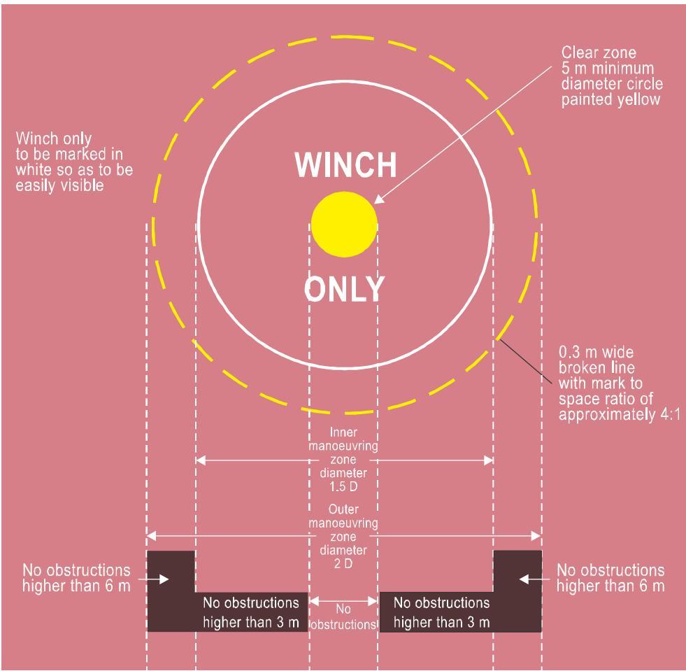
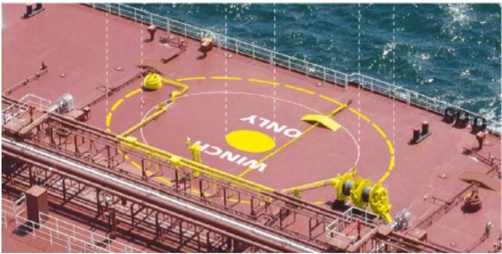
Figure I-7-1 Marking scheme for a shipboard winching area
7.3 LIGHTING OF A WINCHING AREA FOR NIGHT HELI-HOIST OPERATIONS
7.3.1 Where winching area operations are required to be conducted at night, winching area floodlighting should be provided to illuminate the clear zone and the manoeuvring zone areas. Floodlights should be arranged and adequately shielded so as to avoid glare to pilots operating in the hover and to personnel who may be working on the area during periods of non-operation. For a winching area, with its associated obstacle limitation surfaces, it is most likely that this will be achieved using a system of area (high-mounted) floodlighting, rather than a dedicated surface-mounted floodlighting system.
7.3.2 However illumination of the winching area is achieved, it is important to ensure that the spectral distribution of winching area floodlights is such that the surface markings and obstacle markings can be clearly identified. The floodlighting arrangement should ensure that shadows are kept to a minimum.
7.3.3 Obstructions within or immediately adjacent to the manoeuvring zone which may present a hazard to the helicopter conducting winching operations at night, need to be made readily visible from the air during night operations and should be conspicuously illuminated.
7.4 ADDITIONAL OPERATIONAL CONSIDERATIONS
7.4.1 To reduce the risk of a hoist hook or cable becoming fouled, all guard rails, awnings, stanchions, antennae and other obstructions within the vicinity of the manoeuvring zone should, as far as possible, be either removed, lowered or securely stowed. In addition, personnel should be kept well clear of any space immediately beneath the operating area. All doors, portholes, skylights, hatch-covers etc. in the vicinity of the operating area should be closed. This may also apply to deck levels that are below the operating area.
7.4.2 RFF personnel should be deployed in a ready state but sheltered from the helicopter operating area. RFF service requirements for landing areas are addressed in Chapter 6 of this manual. Winching areas should comply with the relevant SOLAS regulation for winching areas.
Chapter 8
MISCELLANEOUS ITEMS
8.1 CRITERIA FOR PARKING AREAS AND PUSH-IN PARKING AREAS
8.1.1 The ability to park a helicopter on an offshore facility or vessel and still be able to use the landing area for other helicopter operations provides greater operational flexibility. A parking area, where provided, should be located within the 150 degree limited obstacle sector (LOS) equipped with markings to provide effective visual cues for flight crews needing to use the parking area.
8.1.2 It is therefore necessary for a parking area to be clearly distinguishable from the touchdown and lift-off area (TLOF). By day, this is achieved by ensuring a good contrast between the surface markings of the landing area and the surface markings of the parking area. For a standard dark green helideck, as described in Chapter 5, 5.10.1, a parking area which is painted a light grey colour utilising a high friction coating will provide suitable contrast (an aluminium surface may be left untreated). For an untreated aluminium landing area, as described in Chapter 5, 5.1.3 and 5.10.2, it will be necessary to select a different colour finish for the parking area (preferably a darker colour than the landing area but avoiding dark green) to achieve a good contrast. (The Figures in this chapter assume that a dark green minimum 1 D final approach and take-off area (FATO) is provided. When an untreated aluminium landing area is selected the underlying colour of the parking area will need to be varied to achieve good contrast).
8.1.3 Ideally, the dimensions of the parking area should accommodate a circle with a minimum diameter of 1 x the D-value of the design helicopter. A minimum clearance between the edge of the parking area and the edge of the landing area of 1/3 (0.33) D based on the design helicopter should be provided. The 1/3 D clearance area represents the parking transition area (PTA) (see Section 8.1.6) and should be kept free of obstacles when a helicopter is located in the parking area. Figure I-8-1 defines the basic scheme for a 1 D FATO/TLOF with associated 1 D parking area:
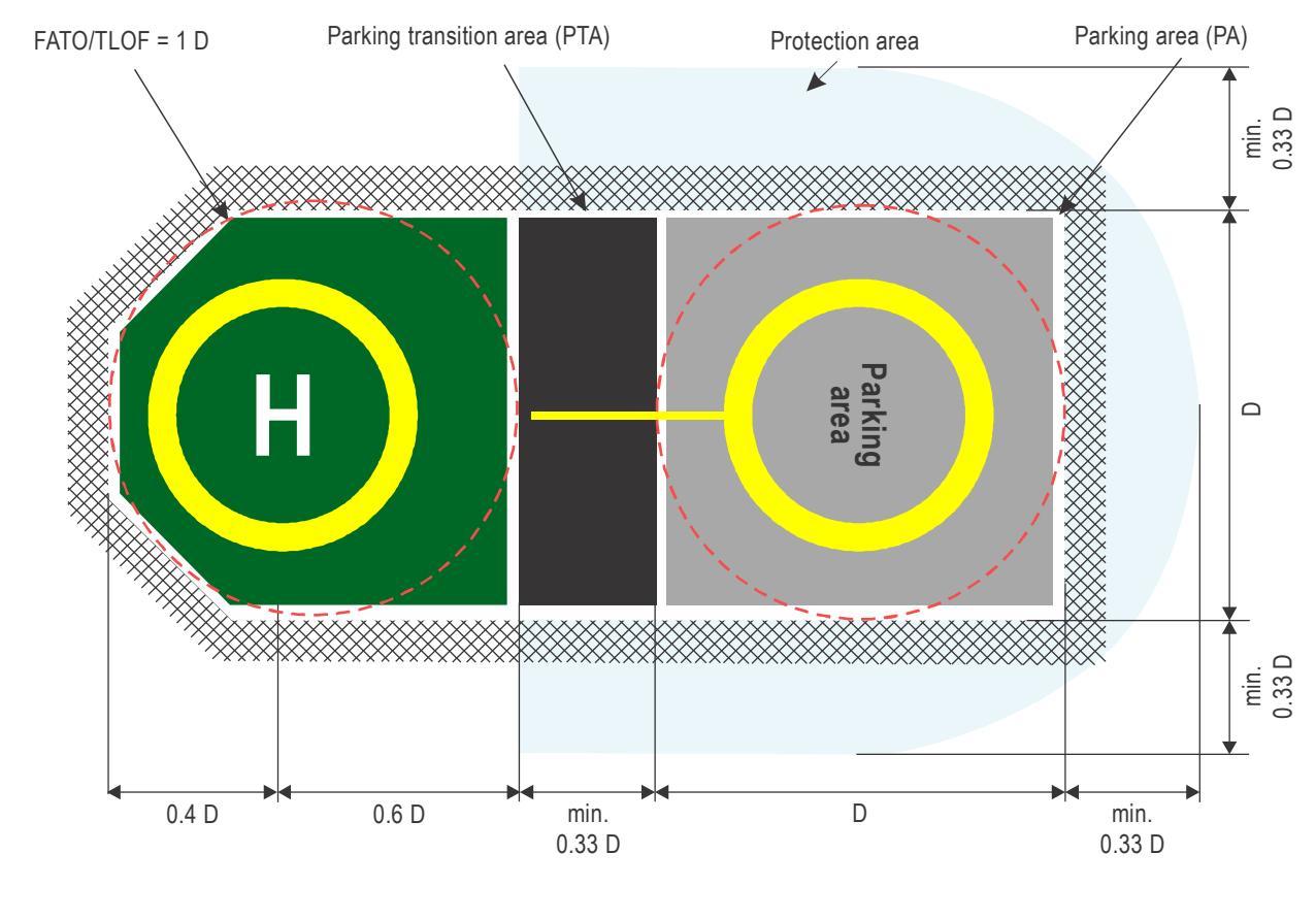
Figure I-8-1. General arrangement — 1 D helideck landing area with associated 1 D parking area — separated by a parking transition area (PTA)
8.1.4 Markings should be incorporated on the parking area surface to provide visual cues to the flight crew to enhance safe operations. Where space (the physical surface) is limited for the parking area, it is permissible to reduce the parking area to be no less than the rotor diameter (RD) of the design helicopter. In this case, the TD/PM circle is offset away from the landing area to ensure a parked helicopter is a safe distance away from the landing area and is contained in the parking area within a hypothetical circle of dimension D. With a reduction in the load-bearing surface of the parking area from D to RD, it is accepted that parts of the helicopter, e.g. the tail rotor or main rotor, may overhang the physical parking area (inboard). The general arrangement for a helideck parking area with offset TD/PM circle is shown in Figure I-8-2.
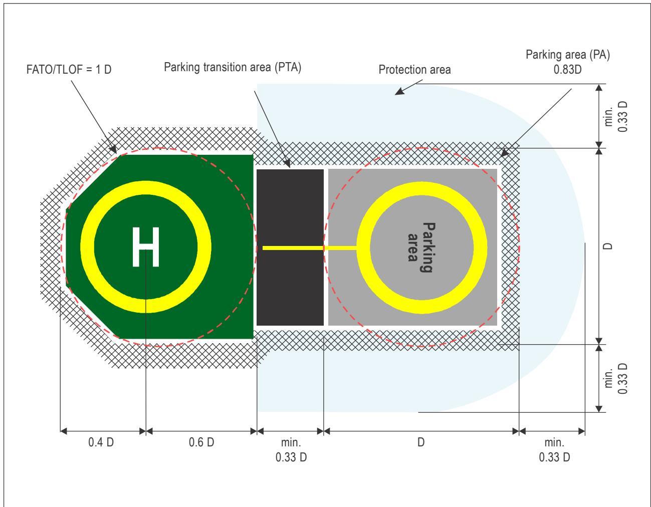
Figure I-8-2. General arrangement for a helideck parking area with offset TD/PM circle
8.1.5 For some offshore facilities, it may not be practical to accommodate a full helideck parking area adjacent to the landing area. In this case, consideration may be given to providing an extension to the landing area, known as a limited parking area (LPA) or push-in parking area (PIPA), separated from the landing area by a PTA (see Section 8.1.6) and designed to accommodate only a fully shutdown helicopter. In this case it is intended helicopters should be shut down on the landing area and ground handled to and from the LPA/ PIPA. The arrangement for an LPA/PIPA is shown in Figure I-8-3. Similar to a parking area, the LPA/PIPA is bounded by a solid white edge buffer line, and should be painted in a colour that contrasts effectively with the landing area (and the PTA).
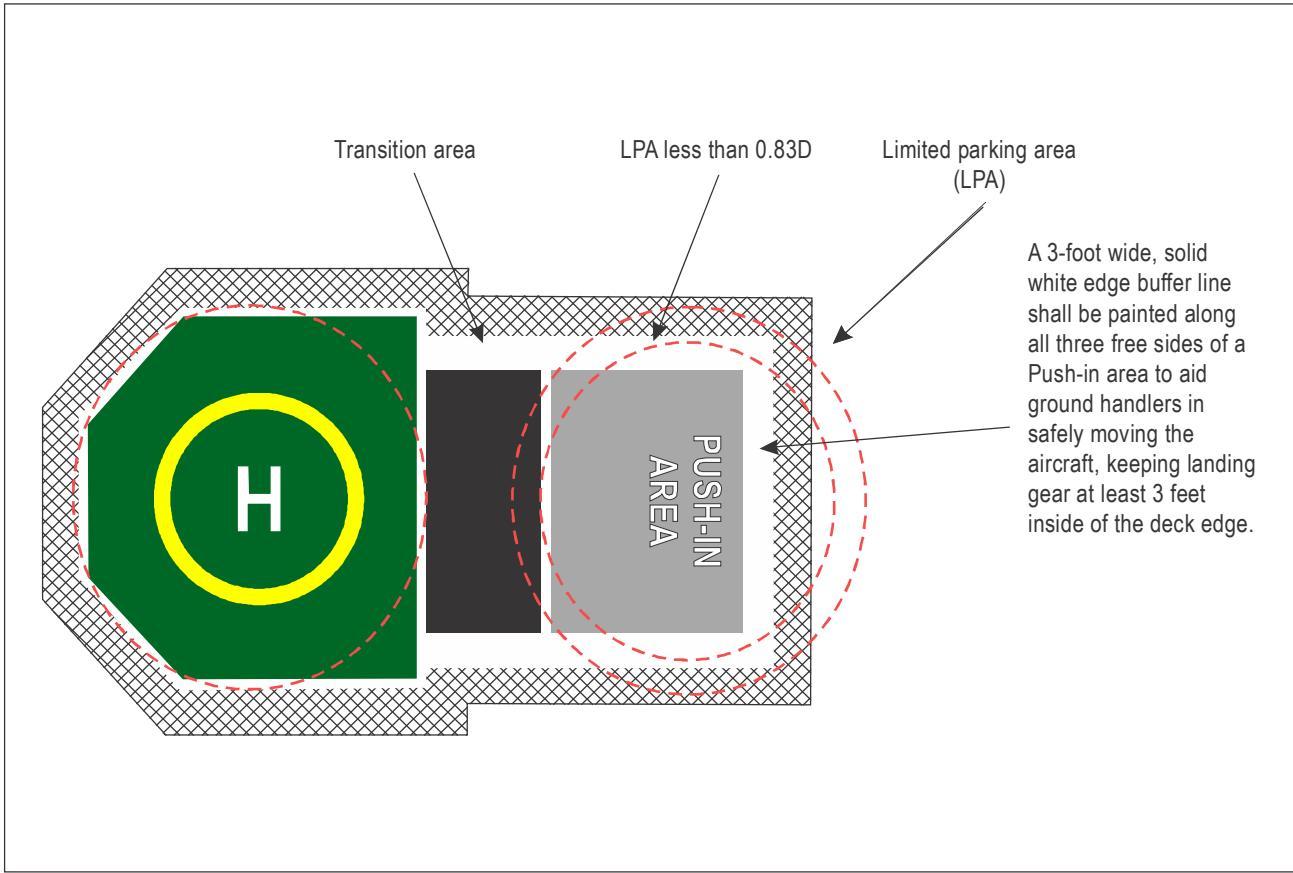
Figure I-8-3. General arrangement for a helideck limited parking area (LPA)/ push-in parking area (PIPA)
8.1.6 In all cases, the PTA provides a sterile area between the edge of the TLOF and the edge of the parking area or LPA/PIPA, and is used to transition the helicopter to and from the parking or LPA/PIPA, whether performing an air taxiing or ground taxiing manoeuvre to the parking area or, in the case of a disabled helicopter, towing or pushing the helicopter clear of the landing area (for an LPA/PIPA the helicopter will always be pushed-in). The PTA provides a minimum 1/3 (0.33) D clearance between a static (parked) helicopter and a helicopter taking off or landing at the TLOF, and should be painted in black for the area between the TLOF perimeter marking and the inboard perimeter of the parking (or pushin parking) area (both defined with 30 cm (1 ft) white lines). During normal operations no part of either helicopter, whether parked in the parking or LPA/push-in parking area, or operating into the landing area, should intrude into the PTA. Assuming the parking area can accommodate the same size (design) helicopter as is assumed for the landing area, there will be no requirement to provide additional markings in the PTA. The parking transition area is shown in Figure I-8-4.
Part I. Offshore heliports Chapter 8. Miscellaneous items
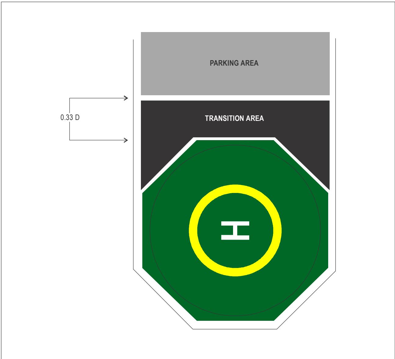
Figure I-8-4. Parking transition area (PTA)
8.1.7 To provide illumination to a parking area at night, and to ensure a pilot is able to differentiate between the parking area and the landing area, it is recommended that deck-mounted floodlights, with louvers, be arranged along either side of the parking area (for guidance on the number and use of floodlighting see Chapter 5, 5.13). Alternatively, where point source (coloured) lights are preferred, or are utilized in addition to floodlights, then the colour green should be avoided for the parking area and the associated PTA — instead blue lights are preferred. The perimeter lights on the parking area do not need to be viewed at range, as do the TLOF perimeter lights (see Chapter 5, 5.12) and therefore parking area perimeter lights should be a blue low intensity light — no less than 5 cd at any angle of elevation (and subject to a maximum of 60 cd at any angle of elevation). Lighting arrangements for parking areas and PIPAs are illustrated in Figures I-8-5 and I-8-6 respectively.
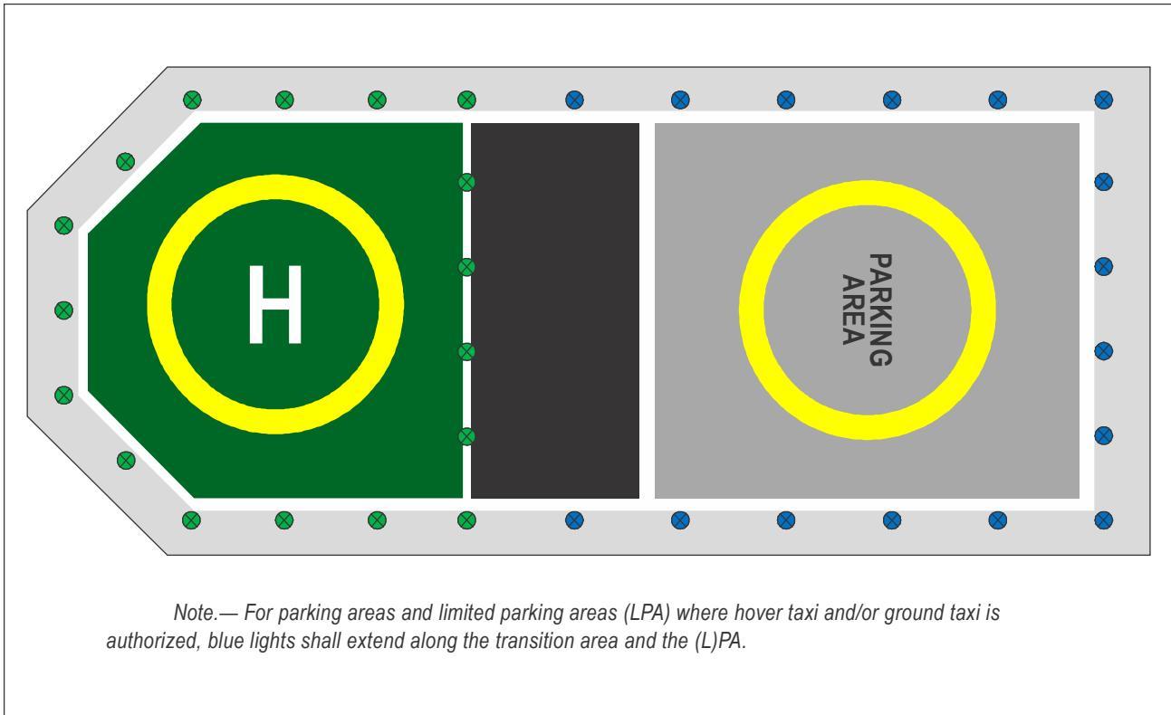
Figure I-8-5. Landing and parking area deck lighting scheme
Part I. Offshore heliports Chapter 8. Miscellaneous items
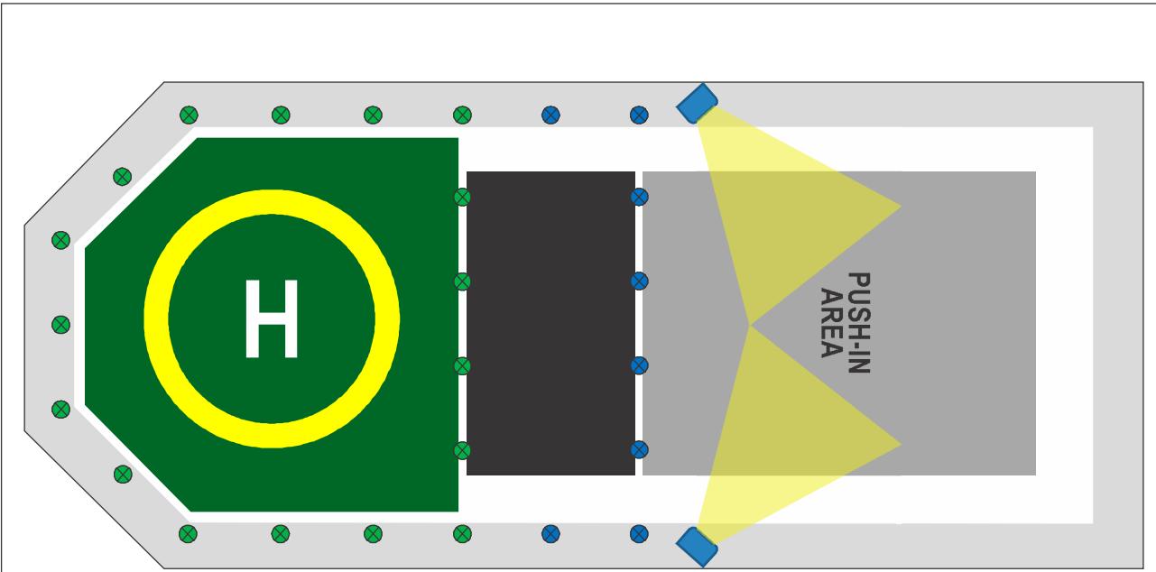
Note.— The PIPA shall be provided with floodlighting. If hover taxi and/or ground taxi is still allowed in the transition area (TA), the TA perimeter lights should be in a blue colour. If no taxiing is allowed in the TA, then floodlights would also be recommended.
Figure I-8-6. Floodlighting scheme for a helideck push-in parking area (PIPA) connected via a PTA to a 0.83 D TLOF
8.1.8 The following sections, supported by Figures I-8-7 and I-8-8, address how a helicopter may be taxied from the landing area to the parking area, by reference to the 15 cm (6 in) yellow taxiway alignment line (see Figures I-8-7 and I-8-8) and then shut down on a heading which keeps the tail clear of any obstructions that may be present in the vicinity of the parking area. Where an obstacle is in close proximity to, or infringes the parking protection area, a “no nose” marking may be necessary to prevent the helicopter tail rotor from coming into line with an object, as illustrated by Figure I-8-8.
8.1.9 Manoeuvring (360 degrees) in the PA as a hover or ground taxi operation is acceptable. The nose of the helicopter should be located over the yellow portion of the PCOM when shutdown, i.e. the nose of the helicopter should not be located over the white portion of the PCOM circle during or while shutdown.
8.1.10 A PCOM marking can be used to avoid the tail rotor being positioned in the vicinity of an exit or emergency exit.
8.1.11 The coverage of the white portion of the PCOM will depend on the size of the obstacle to be avoided but, when used, it is recommended the minimum (angular) size should be no less than 30 degrees.
8.1.12 A “no nose” marking should be used to avoid the tail rotor being positioned in the vicinity of an obstacle that is very near to, or infringes the 0.33 D parking protection area.
8.1.13 A “no nose” marking provides visual cues for aircrew indicating that the “helicopter’s nose” should not be manoeuvred or parked in a particular direction. Figure I-8-8 shows a helicopter manoeuvring and parking orientation restriction, to avoid infringement of a tail rotor hazard.
8.1.14 A “no nose” marking should be on a white background with a red border and the words “no nose” located on the touchdown parking circle (TDPC) as shown in (Figure I-8-8). The “no nose” marking size will depend on the size of the area or obstacle to be avoided by the tail rotor/tail boom. It is recommended that the minimum (angular) size should not be less than 30 degrees. One or multiple obstacles may be covered by this sector.
Note.— Consistent with the arrangements for the landing area (see Chapter 3, 3.5 for helidecks and Chapter 3, 3.6 for shipboard heliports) provisions should be put in place for parking or limited parking/ push-in areas/parking transition areas to ensure adequate surface drainage arrangements and a skid-resistant surface for helicopters and persons operating on the parking or limited parking/push-in parking areas/parking transition areas. When tying down helicopters in the parking area, it is prudent to ensure sufficient tie-down points are located about the touchdown/positioning marking circle (see Chapter 3, 3.5.6 and 3.6.6). A method to secure a helicopter in the push-in area should also be considered. Where necessary a safety device, whether netting or shelving, should be located around the perimeter of the parking area or limited parking/push-in area (and the parking transition area). Parking areas may be provided with one or more access points to allow personnel to move to and from the parking area without having to pass through the PTA to the landing area.
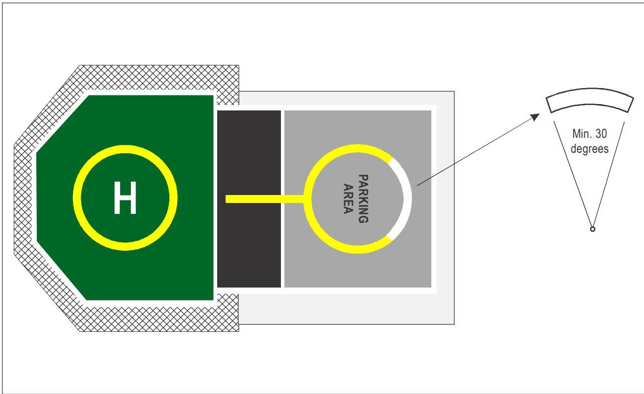
Figure I-8-7. Touchdown parking circle (TDPC) and parking circle orientation marking (PCOM)
Part I. Offshore heliports Chapter 8. Miscellaneous items
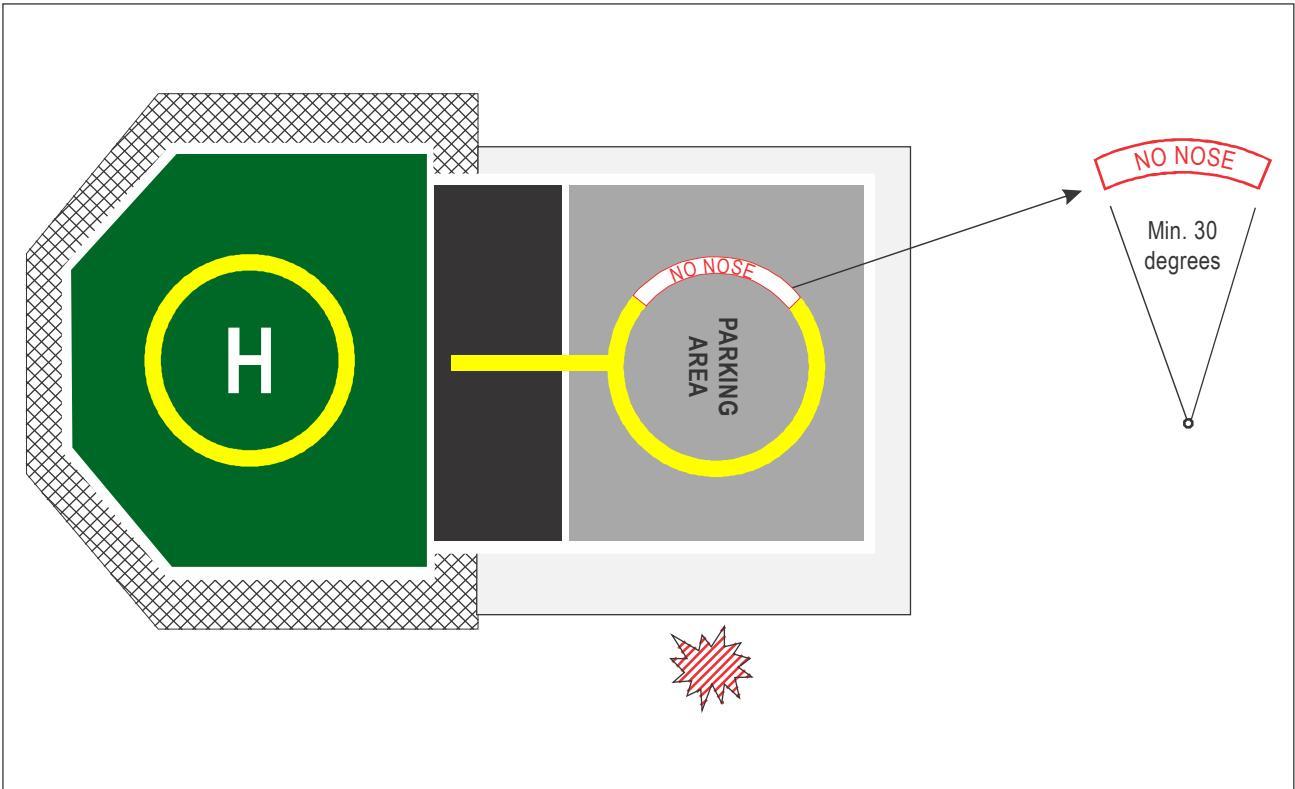
Figure I-8-8. No nose marking
8.2 METEOROLOGICAL EQUIPMENT PROVISION
8.2.1 Accurate, timely and complete meteorological observations are necessary to support safe and efficient helicopter operations. It is recommended that manned, fixed and floating facilities and vessels are provided with an automated means of ascertaining the following meteorological information at all times:
a) wind speed and direction (including variations in direction);
b) air temperature and dew point temperature;
c) QNH and, where applicable, QFE;
d) cloud amount and height of cloud base (above mean sea level (AMSL));
e) visibility; and
f) present weather.
8.2.2 Where a fixed, manned facility is in close proximity to another fixed, manned facility, close as determined by the competent authority, it may not be deemed necessary for every facility to be provided the above equipment, as long as those facilities which are equipped are given to make their information routinely available to the others. For other facilities, a manual means of verifying and updating the visual elements of an observation, i.e. cloud amount and height of base, visibility and present weather, may be used. For not permanently attended installations (NPAIs) and for those fixed and floating facilities and vessels deemed to have a low movement rate, as determined by the competent authority, it may be acceptable just to provide the basic elements of wind, pressure, air temperature and dew point temperature information.
8.2.3 Contingency meteorological observing equipment providing manual measurements of air and dew point temperatures, wind speed direction and pressure is recommended to be provided in case of the failure or unavailability of the automated sensors. It is recommended that personnel who carry out meteorological observations undergo appropriate training for the role and complete periodic refresher training to maintain competency.
8.2.4 Equipment sensors used to provide the data listed in Section 8.2.1. a) to f) should be periodically calibrated in accordance with manufacturers’ recommendations in order to demonstrate continuing adequacy for purpose.
8.2.5 Additional guidance relating to the provision of meteorological information from offshore facilities and vessels may be contained in Annex 3 — Meteorological Service for International Air Navigation.
8.3 DECK MOTIONS REPORTING AND RECORDING
8.3.1 Floating facilities and vessels experience dynamic motions due to wave action, which represent a potential hazard to helicopter operations. Although the ability of a floating facility or vessel to sometimes manoeuvre may be helpful in providing an acceptable wind direction in relation to the helideck/shipboard heliport location, it is likely that floating facilities and vessels will still suffer downtime due to excessive deck motions. Downtime can be minimized by careful consideration of the location of the landing area at the design stage (see Chapter 3, 3.2.5). However, to a greater or lesser degree floating facilities and vessels remain subject to movement at the helideck/heliport in pitch and roll, in deck inclination and in heave (usually measured as rate of heave).
8.3.2 It is necessary for these motions to be recorded by the use of an electronic helideck motion system (HMS) and reported as part of the overall offshore weather report (see Section 8.2.5), prior to landing and during helicopter movements. An HMS should be equipped with a colour-coded display which allows a trained operative to easily determine whether the landing area is in-limits, or is out-of-limits, or is moving towards a condition where it may soon be out-of-limits. Motions at the helideck/heliport should be reported to the helicopter operator to an accuracy of one decimal place. The helicopter pilot, in order to make vital safety decisions, is concerned with the degree of inclination on and the rate of movement of the helideck surface. It is therefore important that reported values are only related to the true vertical and do not relate to any false datum created, for example, by a list created by anchor patterns or displacement.
8.3.3 Research indicates that the likelihood of a helicopter tipping or sliding while touched down on a helideck or shipboard heliport (especially with rotors running, turning and burning on the landing area) is directly related to helideck/heliport accelerations and to the prevailing wind conditions. Ideally an HMS should incorporate additional software which allows for on deck motion severity and wind severity index limits to be recorded and communicated to aircrew; in a similar way that pre-landing limits are disseminated to a pilot.
8.3.4 To provide aircrew with a visual indication of the current status of a helideck/shipboard heliport it may be helpful to employ a traffic light system consisting of three lights mounted at three to four locations around the edge of a helideck/heliport. These lights should avoid the use of the colour green (green is used for TLOF perimeter lights), but could consist of blue/amber and red, where blue is safe within limits, amber is moving out of limits towards an unsafe condition and red is out of limits: unsafe condition.
8.4 COMMUNICATIONS AND NAVIGATION EQUIPMENT
8.4.1 On most facilities, fixed and floating, and on vessels, the radio operator (RO) is the initial and final point of contact between flight crew and the facility/vessel. However, as continuous line of sight to the landing area is often not possible to provide from the radio room, it is advisable to equip helideck/heliport personnel (e.g. HLOs and helideck assistants (HDAs)) with portable aeronautical headsets, the use of which they should be suitably trained in.
8.4.2 A major advantage of having a radio-equipped person on the helideck/heliport is that they can maintain visual as well as radio communication during the circuit, final approach and landing, therefore providing the helicopter crew with further positive identification of the facility (or vessel) and thereby reducing the incidence for a wrong deck landing (see also Chapter 5, 5.1.5). A radio-equipped person is also in a good position to warn of any developing issues while the helicopter is on deck.
8.4.3 Hand-over and general R/T procedures employed should be standard R/T phrases and vocabulary only, to avoid misunderstandings. Communications should be kept brief, avoiding any unnecessary chatter on the selected aeronautical frequency and should be confined to essential dialogue between flight crew and the HLO.
8.4.4 Offshore fixed and floating facilities and vessels that have aeronautical radio equipment and/or aeronautical non-directional beacons (NDBs) on them should hold a valid approval issued by the State in which they operate.
8.5 HELICOPTER REFUELLING OPERATIONS
8.5.1 It is essential to ensure at all times that aviation fuel delivered to helicopters from offshore facilities and vessels is of the highest quality. A major contributor towards ensuring that fuel quality is maintained, and contamination prevented, is the provision of clear, unambiguous product identification on all system components and pipelines, denoting the fuel type (e.g. Jet A-1) following the standard aviation convention for markings and colour codes. Markings should be applied initially during systems manufacture and routinely checked for clarity during subsequent maintenance inspections.
8.5.2 It should be noted that an offshore fuelling system may vary according to the particular application for which it was designed. Nevertheless the elements of all offshore fuelling systems are similar and will include:
a) storage tanks;
b) static storage facilities, and if installed, a sample reclaim tank;
c) a pumping system; and
d) a delivery system.
8.5.3 When preparing a layout design for aviation fuelling systems on offshore facilities and vessels, it is important to make provisions for suitable segregation and bunding of the areas set aside for the tankage and delivery system. Facilities for containing possible fuel leakage and providing fire control should be given full and proper consideration, along with adequate protection from potential dropped objects. The design of the elements of an offshore fuelling system is not addressed in detail in this manual. For detailed guidance, refer to the Air Transport Association Specification 103 (Standard for Jet Fuel Quality Control at Airports).
8.5.4 Fuel storage, handling and quality control are key elements for ensuring, at all times, the safety of aircraft in flight. For this reason, personnel assigned refuelling responsibilities should be certified as properly trained and competent to undertake systems maintenance, inspection and fuelling of helicopters.
8.5.5 Throughout the critical processes of aviation fuel system maintenance and fuelling operations, routine fuel sampling is required to ensure delivered fuel is scrupulously clean and free from contamination that may otherwise enter helicopter fuel tanks and could ultimately result in engine malfunctions.
8.5.6 Fuel samples drawn from transit/static storage tanks and the fuel delivery system should be retained in appropriate containers for a specified period. The containers should be kept in a secure light-excluding store and kept away from sunlight until they are disposed of.
8.5.7 Guidance on the design of containers is provided by the International Air Transport Association (IATA). The IATA fuel guidelines provide an essential set of standards designed to ensure safe and efficient aircraft fuel handling and contribute to training of fuelling operatives for oil companies or into-plane service providers.
8.6 BIRD CONTROL AT NORMALLY UNATTENDED OFFSHORE FACILITIES
8.6.1 Bird guano infestations may be routinely encountered, particularly at NPAIs, and especially at certain times of the year for facilities located in proximity to bird migratory routes. (The problem is most severe at not permanently attended facilities since, at attended facilities, on-board activities will tend to scare the birds away). The effects of bird guano infestation are many and include threats to safe flight operations (e.g. potential for a bird strike during an approach), the obliteration of essential markings (so making touchdown/positioning inaccuracies more likely), a reduction in the friction qualities of the surface (leading to a helicopter sliding over the deck surface) and effects on personnel health and safety due to the highly toxic and slippery nature of guano (e.g. effect on the lungs due to inhalation of dried guano dust, slips on wet guano surfaces). Also to consider are the additional costs incurred through a requirement for more regular maintenance of static equipment on a facility, of damage caused to the interior of the helicopter (guano is trodden onto floor surfaces) and the need to perform high-pressure cleaning on a regular basis to restore the integrity of markings, etc.
8.6.2 Problems caused by the presence of sea birds and guano infestation on or around the landing area should be noted and reported by flight crews. Significant surface contamination is likely to incur flight restrictions where, for example, the build-up of guano has a detrimental effect on the interpretation of surface markings and an inability to maintain an adequate friction surface. Routinely, for affected facilities, flight crew should be encouraged to complete and file helideck condition reports that indicate the current condition of the surface, of helideck lighting (including any outages) and of the windsock (including illumination).
8.6.3 Experience over time in various sectors would suggest that finding permanent solutions to the guano/bird problem can be challenging, and consequently, determining an optimum solution to the problem has proven elusive. In the past, active measures taken to discourage sea birds from roosting on helidecks has included visual deterrents, different audio deterrents (e.g. distress calls) and even combined audio/visual deterrents that build in random changes. However, over time, birds have tended to habituate to any of these solutions that involve audio and/or visual deterrents, even where these incorporate random changes.
8.6.4 One possible solution that has been found to be more effective than most of the aforementioned is the application of pressurised water-spray systems, to which birds do not appear to readily habituate (pressurized water could be delivered from an automated firefighting deck integrated firefighting system (DIFFS) or a ring-main system (RMS) where bird activities are being monitored, from the beach or from a normally attended platform, via a remotely operated TV system (ROTS)). When water combined with an effective bird-scaring device is activated automatically as birds are detected around the landing area, the combination has proven to be relatively effective in dispersing birds that may have encroached onto the helideck. However, it is fair to conclude that current bird-exclusion methods have at best been only partially successful, so there is room for more innovative approaches to bird control measures at helidecks.
Appendix 1-A
SAMPLE RISK ASSESSMENT FOR HELICOPTEROPERATIONS TO HELIDECKS ANDSHIPBOARD HELIPORTS WHICH ARE SUB-1 D
Table I-A-1 could form the basis of an aeronautical study (risk assessment) conducted by, or on behalf of, an offshore helicopter operator when intending to service helidecks or shipboard heliports with limited touchdown directions using helicopters with an overall length (D) greater than the design D of the touchdown and lift-off area (TLOF) (referred to in this document as a sub-1 D operation). The assumption is made that sub-1 D operations will be considered only in the following circumstances and when applying the following conditions:
a) for a helideck that provides a load-bearing surface (represented by the TLOF) of between 0.83 D and 1 D, a minimum 1 D circle (representing the final approach and take-off area (FATO)) should be assured for the containment of the helicopter. From the periphery of the FATO (not the TLOF) the limited obstacle sector (LOS) extends; the non-load-bearing area between the TLOF perimeter and the FATO perimeter should be entirely free of ‘non-permitted’ obstacles, while ensuring that any permitted objects present for the safety of operation that are located on or around the TLOF perimeter should not exceed the obstruction height criteria set out in d) below;
b) this assessment may be considered for any helideck on a fixed offshore installation. A floating installation or vessel that is subject to dynamic motions may be considered provided deck motions are maintained within benign limits as determined by the State of operation, e.g. stable deck conditions – specified criteria in pitch roll and heave;
c) this assessment, when applied to helidecks completed on or before 1 January 2012, or shipboard heliports completed on or before 1 January 2015, may take advantage of an Annex 14, Volume II, alleviation permitting the outboard edge of the (approximately) 1.5 m (5 ft) helideck perimeter netting to extend above the level of the landing area by no more than 25 cm (10 in). However, for helidecks completed on or after 1 January 2012 and shipboard heliports completed on or after 1 January 2015, Annex 14 — Aerodromes, Volume II — Heliports requires that the height of the helideck safety net should be no greater than the adjacent helideck load-bearing surface (TLOF);
d) for helidecks that are less than 1 D and/or having a D-value which is 16.00 m (52.5 ft) or less, Annex 14, Volume, II prescribes the height limit for essential objects around the edge of the TLOF, and in the first segment of the LOS, to be 5 cm (2 in). “Essential objects” permitted around the edge of the TLOF are notified in Chapter 3 of this manual and include helideck guttering with raised kerb, helideck lighting systems and foam monitors (or ring-main system) where provided;
e) Figure I-A-1 illustrates a 0.83 D minimum size TLOF. The inner circle bounded by the octagon-shaped helideck represents the sub-1 D TLOF (in the illustration a 0.83 D load-bearing surface). The outer circle illustrates the 1 D FATO which provides containment of the helicopter and from which is derived the origin of the LOS. Where practical, the chevron denoting the origin of the LOS should be physically marked at the periphery of the FATO, (see Chapter 5, 5.9.5 and Figure I-5-8). The diameter of the FATO is the declared D-value, marked at the chevron; and
f) operations to sub-1 D helidecks and shipboard heliports should not be considered below 0.83 D.
Table I-A-1. Sample risk assessment considerations
| Issues to be addressed | Considerations/mitigations accounting for compromise |
| Reduction of the distance from helideck (TLOF) centre to the limited obstacle sector (LOS) (denoting the origin of the 1st and 2nd segments) | It is essential that clearance from obstacles in the LOS is maintained; for this reason, the sub-1 D TLOF should be surrounded by a 1 D circle (the FATO) that is (with the exception of permitted objects) free of any obstacles. To ensure that obstacle clearances are maintained for the helicopter, the touchdown/ positioning |
| Reduction of suitable and sufficient visual references required for the pilot during all flight phases. | and located at the centre of the TLOF; never offset. Adequate visual cues provided for aircrew are essential for the conduct of safe operations to helidecks. On a sub-1 D helideck, or shipboard heliport with limited touchdown directions, these will, to some degree, be compromised. An aeronautical study should ensure that visual cues, within the field of view (FOV) are adequate for aircrew to perform the following visual tasks: |
| a) identification of helideck location early on in the approach; | |
| b) visual cues to help maintain the sight picture during approach; | |
| c) visual cues on final approach to hover position; | |
| d) visual cues for landing; and | |
| e) visual references on lift-off and hover | |
| It is important that helideck markings and deck mounted lighting (where provided) remain uncontaminated at all times (e.g. deposits of guano on the surface of a | |
| helideck, or shipboard heliport, may compromise markings and/or deck-mounted lighting). A windsock should be provided to facilitate an accurate indication of wind direction and strength over the helideck. For night operations, lighting systems | |
| Reduction of the space available for passengers and crew to | should include effective obstruction lighting in addition to helideck lighting and an illuminated windsock. A reduction of the operating area entails that clearances between passengers/crew moving around the helideck or shipboard heliport avoiding the helicopter's rotor |
| safely alight and embark the helicopter and to transit to and from the operating area safely. | systems by a safe margin are reduced. This reduction should be considered on a helicopter-type specific basis. It should be ensured that suficient access points are available to avoid the situation where passengers and crew have to pass close to helicopter 'no-go' areas (e.g. in relation to main and tail rotor systems). Where personnel are required to transit close to the deck edge, procedures should be |
| Reduction of the space available for securing helicopters for the conduct of safe and efficient refuelling operations (where provided) and for post-crash teams to provide effective fire and rescue intervention in the passengers to escape downwind to safety. | considered to assure the safe movement of passengers. The surface area available should accommodate a sufficient tie-down pattern arrangement to allow the most critical helicopter(s) to be tied-down (where required). Where refuelling operations are required, the area available around the helicopter should allow this to occur safely and efficiently at al times. Sufficient access points should be provided to allow helideck fire and rescue teams to move to the scene of an incident or accident from an upwind location and to allow |
Part I. Offshore heliports Appendix I-A.
| Issues to be addressed | Considerations/mitigations accounting for compromise |
| event of an incident or accidentoccurring. | |
| Helicopter elements will be overpermitted essential objects at theedge of the TLOF. | According to Annex 14 Volume Il, 3.3.13, the permitted height for essential objectslocated around the TLOF in the 210° obstacle-free sector and in the 1st segment ofthe 150° limited obstacle sector was reduced from 25 cm (10 in) to 5 cm (2 in) for aTLOF which is less than 1 D and/or 16 m (52.5 ft) or less. For newbuilds this isregarded as adequate mitigation for the reduction of the dimension of theload-bearing area to address the presence of objects which, because of theirfunction, are required to be located immediately around the TLOF. |
| Reduction of built-in margin toallow for touchdown/positioninginaccuracies during landing. | It should be assumed that even amongst experienced, well trained aircrew therewill inevitably be some degree of variability in the actual point of touchdown withinthe landing area. The TD/PM circle provides an effective visual reference to guidethe handling pilot to the point of touchdown, but scatter has potential to occur,particularly when external factors beyond a pilot's control come into play. This mayinclude the influences of prevailing meteorological conditions at the time of landing(e.g. wind, precipitation etc.), and/or any helideck environmental effectsencountered (e.g. turbulence, thermal effects). It is essential that a good visualmeans of assessing wind strength and direction is always provided for the pilot byday and by night. Markings should be kept free of contamination which may reducea pilot's ability to touchdown accurately. The TD/PM circle and “H" should be lit(or adequately illuminated) for night operations. |
| Reduction of helpful groundcushion effect from rotordownwash | It is a condition of Annex 14 Volume I that the TLOF should provide ground effect.A reduction of the load-bearing area (TLOF) for sub-1 D operations means that thebeneficial effect of ground cushion willikely suffer some reduction. The reductionof helpful ground cushion needs to be considered particularly when operating to asub-1D helideck with a perforated surface, i.e. helideck designs that incorporate apassive fire-retarding feature which allows unburned fuel to drain away throughspecially manufactured holes, forming a drain-hole pattern over the surface of theTLOF. |
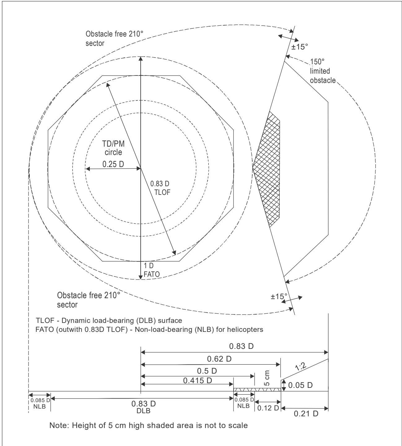
Figure I-A-1. Obstacle limitation surface and sectors for a 0.83 D TLOF
SPECIFICATION FOR HELIDECK LIGHTING SCHEME COMPRISING:PERIMETER LIGHTS, LIT TOUCHDOWN/POSITIONING MARKINGAND LIT HELIPORT IDENTIFICATION MARKING
1. OVERALL OPERATIONAL REQUIREMENT
1.1 The lighting configuration should be designed to be visible over a range of 3600 in azimuth. It is possible, however, that on some offshore installations the lighting may be obscured from the pilots’ view by topsides structure when viewed from some directions. The design of the helideck lighting is not required to address any such obscuration.
1.2 The visibility of the lighting configuration should be compatible with the normal range of helicopter vertical approach paths from a range of 2 NM.
1.3 The purpose of the lighting configuration is to aid the helicopter pilot perform the necessary visual tasks during approach and landing as stated in Table I-B-1.
Table I-B-1. Visual tasks during approach and landing
| Phase of Approach | Visual Task | Visual Cues/ Aids | Desired Range (NM) | |
| 5000mmet. vis. | 1400mmet. vis. | |||
| Helideck locationand identification | Search within platformstructure. | shape of helideck;colour of helideck;luminance of helideck; andperimeter lighting. | 1.5(2.8 km) | 0.75(1.4 km) |
| Final approach | Detect helicopter position inthree axes.Detect rate of change ofposition. | apparent size/shape andchange of size/shape ofhelideck; andorientation and change oforientation of knownfeatures/markings/lights. | 1.0(1.8 km) | 0.5(900m) |
| Hover and landing | Detect helicopter attitudeposition and rate of changeof position in three axes(six degrees of freedom). | known features/markings/lights; andhelideck texture. | 0.03(50 m) | 0.03(50m) |
1.4 The minimum intensities of the lighting configuration should be adequate to ensure that, for a minimum meteorological visibility (met. vis.) of 1 400 m and an illuminance threshold of 10-6.1 lux, each feature of the system is visible and useable at night from ranges in accordance with the following:
a) the perimeter lights are to be visible and usable at night from a minimum range of 0.75 NM;
b) the touchdown/positioning marking (TD/PM) circle on the helideck is to be visible and usable at night from a range of 0.5 NM; and
c) the heliport identification marking (‘H’) is visible and usable at night from a range of 0.25 NM.
1.5 The minimum ranges at which the TD/PM Circle and ‘H’ are visible and useable should still be achieved even where a correctly fitted landing net covers the lighting.
1.6 The design of the perimeter lights, TD/PM Circle and ‘H’ should be such that the luminance of the perimeter lights is equal to or greater than that of the TD/PM circle segments, and the luminance of the TD/PM circle segments equal to or greater than that of the ‘H’.
1.7 The design of the TD/PM Circle and ‘H’ should include a facility to enable their intensity to be increased by up to approximately two times the figures given in this specification to permit a once-off (tamperproof) adjustment at installation; the average intensity over 3600 in azimuth at each elevation should not exceed the maximum figures. The purpose of this facility is to ensure adequate performance at installations with high levels of background lighting without risking glare at less well-lit installations. The TD/PM Circle and ‘H’ should be adjusted together using a single control to ensure that the balance of the overall lighting system is maintained in both the ‘standard’ and ‘bright’ settings.
2. DEFINITIONS
2.1 The following definitions should apply:
2.1.1 Lighting Element. A lighting element is a light source within a segment or subsection and may be discrete (e.g. a Light Emitting Diode (LED)) or continuous (e.g. fibre optic cable, electro luminescent panel). An individual lighting element may consist of a single light source or multiple light sources arranged in a group or cluster and may include a lens/diffuser.
2.1.2 Segment. A segment is a section of the TD/PM circle lighting. For the purposes of this specification, the dimensions of a segment are the length and width of the smallest possible rectangular area that is defined by the outer edges of the lighting elements, including any lenses/diffusers.
2.1.3 Subsection. A subsection is an individual section of the ‘H’ lighting. For the purposes of this specification, the dimensions of a subsection are the length and width of the smallest possible rectangular area that is defined by the outer edges of the lighting elements, including any lenses/diffusers.
3. THE PERIMETER LIGHT REQUIREMENT
3.1 Configuration
Perimeter lights, spaced at intervals of not more than 3 m, should be fitted around the perimeter of the landing area.
3.2 Mechanical Constraints
For any helideck 1 D or greater, where the D-value is also greater than 16 m (52.5 ft), the perimeter lights should not exceed a height of 25 cm (10 in), but ideally 15 cm (6 in), above the surface of the helideck. Where a helideck has a D-value of 16 m (52.5 ft) or less and/or is less than 1 D, the perimeter lights should not exceed a height of 5 cm above the surface of the helideck.
3.3 Light Intensity
3.3.1 The minimum light intensity profile is given in Table I-B-2 below:
Table I-B-2. Minimum light intensity profile for perimeter lights
| Elevation | Azimuth | Intensity (min) |
| 00 to 10 | $- 1 8 0 ^ { 0 } \mathrm { t } 0 + 1 8 0 ^ { 0 }$ | 30cd |
| $> 1 0 ^ { 0 } \mathrm { \Delta t o \ } 2 0 ^ { 0 }$ | $- 1 8 0 ^ { 0 } \mathrm { t } 0 + 1 8 0 ^ { 0 }$ | 15 cd |
| $> 2 0 ^ { 0 } \mathrm { t o } 9 0 ^ { 0 }$ | $- 1 8 0 ^ { 0 } \mathrm { t } 0 + 1 8 0 ^ { 0 }$ | 3 cd |
3.3.2 No perimeter light should have an intensity of greater than 60 cd at any angle of elevation. Note that the design of the perimeter lights should be such that the luminance of the perimeter lights is equal to or greater than that of the TD/PM Circle segments.
3.4 Colour
3.4.1 The colour of the light emitted by the perimeter lights should be green, as defined in Annex 14, Volume 1, Appendix 1, paragraph 2.3.1 (c), whose chromaticity lies within the following boundaries:
Yellow boundary x = 0.310
White boundary $\mathsf { x } = 0 . 6 2 5 \ \mathsf { y } - 0 . 0 4 1$
Blue boundary $\mathsf { y } = 0 . 4 0 0$
3.4.2 The above assumes that solid state light sources are used. Annex 14, Volume 1, Appendix 1, paragraph 2.1.1 (c), should be applied if filament light sources are used.
3.5 Serviceability
3.5.1 The perimeter lighting is considered serviceable provided that at least 90 per cent of the lights are serviceable, and providing that any unserviceable lights are not adjacent to each other.
4. THE TOUCHDOWN/POSITIONING MARKING CIRCLE REQUIREMENT
4.1 Configuration
The lit TD/PM circle should be superimposed on the yellow painted marking, such that it is concentric with the painted circle and contained within it. It should comprise one or more concentric circles of at least sixteen discrete lighting segments, of at least 40 mm (1.5 in) minimum width. The segments should either be straight or curve in sympathy with the painted circle. A single circle should be positioned such that the radius of the circle formed by the centre line of the lighting segments is within 10 cm (4 in) of the mean radius of the painted circle. Multiple circles should be symmetrically disposed about the mean radius of the painted circle, each circle individually meeting the specification contained in this Appendix. The lighting segments should be of such a length as to provide coverage of between 50 per cent and 75 per cent of the circumference and be equidistantly placed with the gaps between them not less than 0.5 m (1.6 ft). A single non-standard gap up to 25 per cent larger or smaller than the remainder of the circle is permitted at one location to facilitate cable entry. The mechanical housing should be coloured yellow.
4.2 Mechanical constraints
4.2.1 The height of the lit TD/PM circle fixtures (e.g. segments) and any associated cabling should be as low as possible and should not exceed 25 mm (1 in). The overall height of the system, taking account of any mounting arrangements, should be kept to a minimum. So as not to present a trip hazard, the segments should not present any vertical outside edge greater than 6 mm (0.2 in) without chamfering at an angle not exceeding 300 from the horizontal.
4.2.2 The overall effect of the lighting segments and cabling on deck friction should be minimized. Wherever practical, the surfaces of the lighting segments should meet the minimum deck friction limit coefficient (µ) of 0.65, e.g. on non-illuminated surfaces.
4.2.3 The TD/PM circle lighting components, fitments and cabling should be able to withstand a pressure of at least 1 655 kPa (240 lbs/in2) and ideally 3 250 kPa (471 lbs/in2) without damage.
4.3 Intensity
4.3.1 The light intensity for each of the lighting segments, when viewed at angles of azimuth over the range +80° to -80° from the normal to the longitudinal axis of the strip (see Figure I-B-1), should be as defined in Table I-B-3.
Table I-B-3. Light intensity for lighting segments on the TD/PM circle
| Elevation | Intensity | |
| Min | Max | |
| 00 to 100 | As a function of segment length as definedin Figure I-B-2. | 60 cd |
| >10° to 200 | 25% of min intensity > 00 to 100 | 45 cd |
| >200to 900 | 5% of min intensity > 00 to 100 | 15 cd |
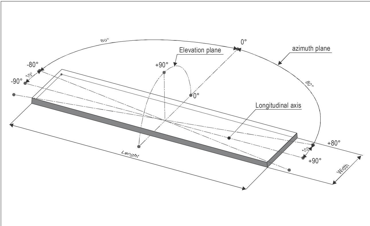
Figure I-B-1. TD/PM segment measurement axis system
4.3.2 For the remaining angles of azimuth on either side of the longitudinal axis of the segment, the maximum intensity should be as defined in Table I-B-3.
4.3.3 The intensity of each lighting segment should be nominally symmetrical about its longitudinal axis. The design of the TD/PM circle should be such that the luminance of the TD/PM circle segments is equal to or greater than the subsections of the ‘H’.
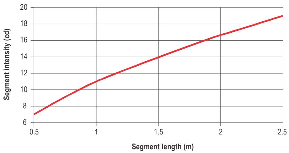
Figure I-B-2. TD/PM Segment intensity versus segment length
Note.— Given the minimum gap size of 0.5 m (1.6 ft) and the minimum coverage of 50 per cent, the minimum segment length is 0.5 m (1.6 ft). The maximum segment length depends on deck size but is given by selecting the minimum number of segments (16) and the maximum coverage (75 per cent).
4.3.4 If a segment is made up of a number of individual lighting elements (e.g. LEDs) then they should be of the same nominal performance (i.e. within manufacturing tolerances) and be equidistantly spaced throughout the segment to aid textural cueing. Minimum spacing between the illuminated areas of the lighting elements should be 3 cm (1.2 in) and maximum spacing 10 cm (4 in).
4.3.5 On the assumption that the intensities of the lighting elements will add linearly at longer viewing ranges where intensity is more important, the minimum intensity of each lighting element (i) should be given by the formula:
$$ \mathsf { i } = \mathsf { I } / \mathsf { n } $$
Note.—The maximum intensity of a lighting element at each angle of elevation should also be divided by the number of lighting elements within the segment.
4.3.6 If the segment comprises a continuous lighting element (e.g. fibre optic cable, electro luminescent panel), then to achieve textural cueing at short range, the element should be masked at 3 cm (1.2 in) intervals on a 1:1 mark-space ratio.
4.4 Colour
4.4.1 The colour of the light emitted by the TD/PM circle should be yellow, as defined in Annex 14, Volume 1, Appendix 1, paragraph 2.3.1 (b), whose chromaticity is within the following boundaries:
$$ \mathsf { R e d \ b o u n d a r y \qquad y = 0 . 3 8 7 } $$
$$ \mathsf { W h i t e \ b o u n d a r y \qquad y = 0 . 9 8 0 - x } $$
$$ \mathsf { G r e e n b o u n d a r y } \qquad \mathsf { y } = 0 . 7 2 7 \times + 0 . 0 5 4 $$
4.4.2 The above assumes that solid state light sources are used. Annex 14, Volume 1, Appendix 1, paragraph 2.1.1 (c), should be applied if filament light sources are used.
4.5 Serviceability
The TD/PM circle: At least 90 per cent of the lighting elements should be operating for the TD/PM circle to be considered serviceable.
5. THE HELIPORT IDENTIFICATION MARKING REQUIREMENT
5.1 Configuration
5.1.1 The lit heliport identification marking (‘H’) should be superimposed on the 4 m x 3 m (13 ft x 10 ft) white painted ‘H’ (limb width 0.75 m (2.5 ft)). The lit ‘H’ should be 3.9 m to 4.1 m (13 ft x 13.5 ft) high, 2.9 to 3.1 m (9.5 ft x 10 ft) wide and have a stroke width of 0.7 m to 0.8 m (2.3 ft x 2.6 ft). The centre point of the lit ‘H’ may be offset from the centre point of the painted ‘H’ in any direction by up to 10 cm (4 in) in order to facilitate installation (e.g. avoid a DIFFS nozzle on the helideck surface). The limbs should be lit in outline form as shown in Figure I-B-3.
5.1.2 An outline lit ‘H’ should comprise subsections of between 80 mm (3 in) and 100 mm (4 in) wide around the outer edge of the painted ‘H’ (see Figure I-B-3). There are no restrictions on the length of the subsections, but the gaps between them should not be greater than 10 cm (4 in). The mechanical housing should be coloured white.
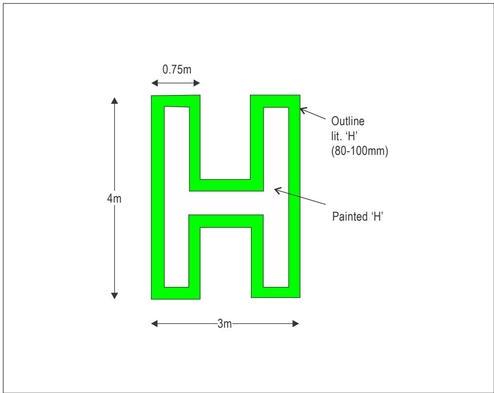
Figure I-B-3. Configuration and nominal dimensions of heliport identification marking ‘H’
5.2 Mechanical constraints
5.2.1 The height of the lit ‘H’ fixtures (e.g. subsections) and any associated cabling should be as low as possible and should not exceed 25 mm (1 in). The overall height of the system, taking account of any mounting arrangements, should be kept to a minimum. So as not to present a trip hazard, the lighting strips should not present any vertical outside edge greater than 6 mm (0.2 in) without chamfering at an angle not exceeding 300 from the horizontal.
5.2.2 The overall effect of the lighting subsections and cabling on deck friction should be minimized. Wherever practical, the surfaces of the lighting subsections should meet the minimum deck friction limit coefficient (µ) of 0.65, e.g. on non-illuminated surfaces.
5.2.3 The ’H’ lighting components, fitments and cabling should be able to withstand a pressure of at least
1 655 kPa (240 lbs/in2) and ideally 3 250 kPa (471 lbs/in2) without damage.
5.3 Intensity
5.3.1 The intensity of the lighting along the 4 m (13 ft) edge of an outline ‘H’ over all angles of azimuth is given in Table I-B-4 below.
Table I-B-4. Light Intensity of the 4 m edge of the ‘H’
| Elevation | Intensity | |
| Min | Max | |
| $2 ^ { 0 } \mathrm { t o } \ 1 2 ^ { \circ }$ | 3.5 cd | 60 cd |
| ${ > } 1 2 ^ { 0 } \mathrm { t o } 2 0 ^ { 0 }$ | 0.5 cd | 30 cd |
| ${ } > 2 0 ^ { 0 } \ \mathsf { t o } \ 9 0 ^ { 0 }$ | 0.2 cd | 10 cd |
Note.—For the purposes of demonstrating compliance with this specification, a subsection of the lighting forming the 4 m (13 ft) edge of the ‘H’ may be used. The minimum length of the subsection should be 0.5 m (1.6 ft). When testing a subsection, the light intensities defined in Table I-B-4 apply only when viewed at angles of azimuth over the range $+ 8 0 ^ { o } t o \ - 8 0 ^ { o }$ from the normal to the longitudinal axis of the strip (see Figure 1). For the remaining angles of azimuth on either side of the longitudinal axis of the subsection, the maximum intensity should be as defined in Table I-B-4.
5.3.2 The outline of the H should be formed using the same lighting elements throughout.
5.3.3 If a subsection is made up of individual lighting elements (e.g. LED’s) then they should be of nominally identical performance (i.e. within manufacturing tolerances) and be equidistantly spaced within the subsection to aid textural cueing. Minimum spacing between the illuminated areas of the lighting elements should be 3 cm (1.2 in) and maximum spacing 10 cm (4 in).
5.3.4 With reference to paragraph 4.3.5, due to the shorter viewing ranges for the ‘H’ and the low intensities involved, the minimum intensity of each lighting element (i) for all angles of elevation (i.e. 20 to 900) should be given by the formula:
$$ \mathsf { i } = \mathsf { I } / \mathsf { n } $$
where: I = required minimum intensity of subsection at the ‘look down’
(elevation) angle between $2 ^ { 0 }$ and $1 2 ^ { 0 }$ (see Table I-B-4).
n = the number of lighting elements within the subsection
Note.—The maximum intensity of each lighting element at any angle of elevation should be the maximum between $_ { 2 ^ { 0 } }$ and $1 2 ^ { 0 }$ (see Table I-B-4) divided by the number of lighting elements within the subsection.
5.3.5 If the ‘H’ is constructed from a continuous light element (e.g. fibre optic cables or panels, electroluminescent panels), the luminance (B) of the 4 m (13 ft) edge of the outline ‘H’ should be given by the formula:
$$ \mathsf { B } = \mathsf { I } / \mathsf { A } $$
5.3.6 If the subsection comprises a continuous lighting element (e.g. fibre optic cable, electro luminescent panel), then to achieve textural cueing at short range, the element should be masked at 3 cm (1.2 in) intervals on a 1:1 mark space ratio.
5.4 Colour
5.4.1 The colour of the ‘H’ should be green, as defined in Annex 14, Volume 1, Appendix 1, paragraph 2.3.1(c), whose chromaticity is within the following boundaries:
$$ \mathsf { Y e l l o w b o u n d a r y } \qquad \mathsf { x } = 0 . 3 1 0 $$
$$ \begin{array} { r } { \mathsf { W h i t e \ b o u n d a r y \qquad x = 0 . 6 2 5 y - 0 . 0 4 1 } } \end{array} $$
$$ \mathsf { B l u e \ b o u n d a r y \qquad y = 0 . 4 0 0 } $$
5.4.2 The above assumes that solid state light sources are used. Annex 14, Volume 1, Appendix 1, paragraph 2.1.1 (c) should be applied if filament light sources are used.
5.5 Serviceability
5.5.1 The ‘H’: At least 90 per cent of the lighting elements should be operating for the ‘H’ to be considered serviceable.
6. GENERAL CHARACTERISTICS
The general characteristics detailed below apply to perimeter lighting as well as the TD/PM circle and ‘H’ lighting except where otherwise stated.
6.1 Requirements
6.1.1 The following items are fully defined and form firm requirements.
6.1.2 All lighting components should be tested by an independent test house. The photometrical and colour measurements performed in the optical department of this test house should be accredited according to the version of EN ISO/IEC 17025 current at the time of the testing. The angular sampling intervals should be: every $1 0 ^ { 0 }$ in azimuth; every $1 ^ { 0 }$ from $0 ^ { 0 }$ to 100; every $2 ^ { 0 }$ from $ 1 0 ^ { 0 }$ to $\scriptstyle 2 0 ^ { 0 }$ and every $5 ^ { 0 }$ from $\scriptstyle 2 0 ^ { 0 }$ to ${ \mathfrak { g } } 0 ^ { 0 }$ in elevation.
6.1.3 As regards the attachment of the TD/PM circle and ‘H’ to the helideck, the failure mode requiring consideration is detachment of components of the TD/PM circle and ‘H’ lighting due to shear loads generated during helicopter landings. The maximum horizontal load may be assumed to be the maximum take-off mass (MTOM) of the largest helicopter for which the helideck is designed multiplied by 0.5, distributed equally between the main undercarriage legs. This requirement applies to components of the circle and H lighting having an installed height greater than 6 mm (0.2 in) and a plan view area greater than or equal to 200 cm2 (6.6 ft2).
Note 1.— Example — for a helicopter MTOM of 14 600 kg (32 187 lbs), a horizontal load of 35.8 kN should be assumed.
Note 2.— For components having plan areas up to and including 1 000 cm2 (33 ft2), the horizontal load may be assumed to be shared equally between all fasteners providing they are approximately equally spaced. For larger components, the distribution of horizontal loads should be considered.
6.1.4 Provision should be included in the design and installation of the system to allow for the effective drainage of the helideck areas inside the TD/PM circle and the ‘H’ lighting. The design of the lighting and its installation should be such that, when mounted on a smooth flat plate with a slope of 1:100, a fluid spill of 200 litres inside the ‘H’ lighting will drain from the circle within 2 minutes. The maximum drainage time applies primarily to aviation fuel, but water may be used for test purposes. The maximum drainage time does not apply to firefighting agents.
Note.— Drainage may be demonstrated using a mock-up of a one quarter segment of a helideck of D-value at least 20 m, configured as shown in Figure I-B-4, and a fluid quantity of 100 litres. The surface of the test helideck should have a white or light-coloured finish and the water (or other fluid used for the test) should be of a contrasting colour (e.g. by use of a suitable dye) to assist the detection of fluid remaining after 2 minutes.
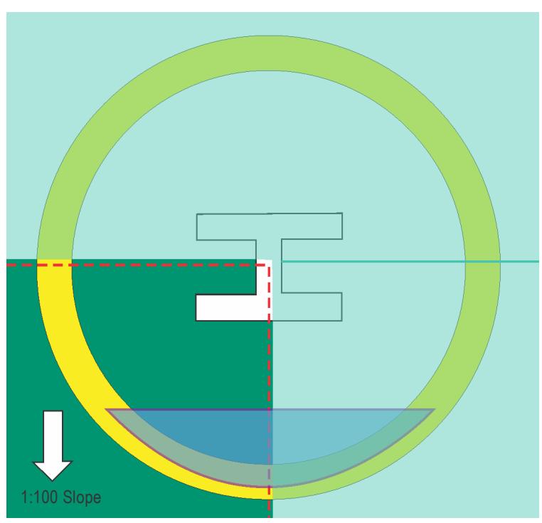
Figure I-B-4. Configuration of quarter segment drainage test mock-up
6.2 Other considerations
6.2.1 The considerations detailed in this section are presented to make equipment designers aware of the operating environment and customer expectations during the design of products or systems. They do not represent formal requirements but are desirable design considerations of a good lighting system.
6.2.2 All lighting components and fitments should meet safety regulations relevant to a helideck environment, such as explosion proofing (Zone 1 or 2 as appropriate) and flammability, and be tested by a notified body in accordance with the equipment for potentially explosive atmospheres (ATEX) directive or equivalent locally applicable hazardous area certification standards.
6.2.3 All lighting components and fitments installed on the surface of the helideck should be resistant to attack by fluids that they will likely or inevitably be exposed to, such as: fuel, hydraulic fluid, helicopter engine and gearbox oils; those used for de-icing, cleaning and firefighting; any fluids used in the assembly or installation of the lighting, e.g. thread locking fluid. In addition, they should be resistant to ultraviolet (UV) light, rain, sea spray, guano, snow and ice. Components should be immersed in each of the fluids individually for a period representative of the likely exposure in-service and then checked to ensure no degradation of mechanical properties (i.e. surface friction and resistance to contact pressure), any discolouration, or any clouding of lenses/diffusers. Any other substances that may come into contact with the system that may cause damage should be identified in the installation and maintenance documentation.
6.2.4 All lighting components and fitments that are mounted on the surface of the helideck should be able to operate within a temperature range appropriate for the local ambient conditions.
6.2.5 All cabling should utilize low smoke/toxicity, flame retardant cable. Any through-the-deck cable routing and connections should use sealed glands, of a type approved for helideck use.
6.2.6 All lighting components and fitments should meet International Electrotechnical Commission (IEC) Ingress Protection (IP) standards according to the version of IEC 60529 current at the time of testing appropriate to their location, use and recommended cleaning procedures. The intent is that the equipment should be compatible with deck cleaning activities using pressure washers and local floodlight (i.e. puddling) on the surface of the helideck. It is expected that this will entail meeting at least IP66 (dust tight and resistant to powerful water jetting), IP67 (dust tight and resistant to temporary submersion in water) and/or IP69 (dust tight and resistant to close range high pressure, high temperature jetting) should also be considered and applied where appropriate.
Note.— Except where flush-mounted (e.g. where used to delineate the landing area from an adjacent parking area), perimeter lights need only to meet IP66. Lighting equipment mounted on the surface of the helideck (e.g. circle and ‘H’ lighting) should also meet IP67. Any lighting equipment that is to be subject to high pressure cleaning should also meet IP69.
6.2.7 Control panels that may be required for helideck lighting systems are not covered by this Appendix. It is the responsibility of the duty holder/engineering contractor to select and integrate control panels into the installation safety and control systems and to ensure that all such equipment complies with the relevant engineering standards for design and operation.
Appendix I-C
DRAINAGE CALCULATION
Helideck Drainage Capacity Check and Calculation
For 20.88m Octagonal Helideck
The following calculation is performed to check on the adequacy of the gutters and drainage header pipes when the firefighting equipment is activated.
The calculation is based on ICAO requirements of a minimum 5.5 litres per minute per m2 application rate.
This calculation is based on a typical regular octagon helideck encompassing a 20.88m D-value diameter designed for the Sikorsky S-92A Helicopter.
• The calculation considers the worst case scenario of combined fuel leakage, rainfall and firewater.
HELIDECK SIZE: 20.88m Octagonal
DESIGN HELICOPTER: Sikorsky S-92A
ASSUMED FUEL CAPACITY: 1130 US Gallons
= 4.28 m3
| Item | Helicopter | |
| Unit | S92A | |
| Assumed FuelLoad | ltrs | 4278 |
| US Galls | 1130 | |
| Min. Foam/ Waterapplication rate | ltrs/ min | 1883 |
A) CONVERSION:
1 Gallon = 0.0379 m3
1 Hectare 10 000 m2
1 m3 1 000 litres
B) NOTATIONS:
Qr = run-off of fluid in m3/sec Qd = gutter uniform flow in m3/sec
C = run-off coefficient based on the Rational n = roughness coefficient
Method.
I = average rainfall intensity in mm/hr p = wetted perimeter of gutter
A = Helideck octagonal surface catchment area S = bed gradient
in m2
A1 = Sectional area of gutter R = Hydraulic radius
Q = Vertical pipe discharge capacity g = Specific wt. of water
c = Coefficient of contraction from orifice h = Water head
H = sectional height of gutter W = sectional width of gutter
C) DUE TO RAINFALL RUN-OFF FOR HELIDECK SURFACE AREA:
s
Rational formula: Qr = C * I * A
C = 0.65
I = 120 mm/hr (rainfall intensity =
120mm/hr) A a
= 3.278E-05 m/s
Area of Helideck = S * S - a * a
Where S is the span of the octagon and a the length of one of
the sides
= 361.17 m2
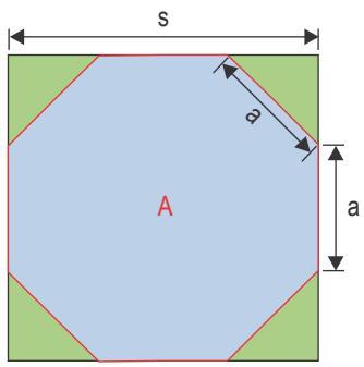
Therefore, Qr = 0.0077 m3/sec
= 462 Litres/min
D) COMPUTATION OF DISCHARGE CAPACITY OF THE GUTTER HEADER PIPES (SCUPPERS):
No. of perimeter pipe for the scuppers = 6 nos. Considering 6 nos. of pipe effective Considering 6 nos. of pipe effective and taking the gutter header pipe as an Orifice,
$$ \begin{array} { r l r } { = } & { { } } & { \mathsf { c } ^ { \star } \mathsf { A p } ^ { \star } \mathsf { s q r t } ( 2 ^ { \star } \mathsf { g } ^ { \star } \mathsf { h } ) } \end{array} $$
Discharge Q
c = 0.5 (Value achieved when the area of choke is divided
by the area of the pipe)
g = 9.81 m/s2
h = 0.180 m
(The total height of gutter is 0.2m. Consider 90% full,
h = 0.18m)
Pipe dia. (Inside) = 0.146 m (φ152mm aluminium pipe having thickness of
3mm)
No. of eff. Pipe, N = 6 (Assumed effective pipe nos)
Area of one pipe, Ap = 0.017 m2
Therefore, Q = 0.01573 m3/ sec (for 1 pipe)
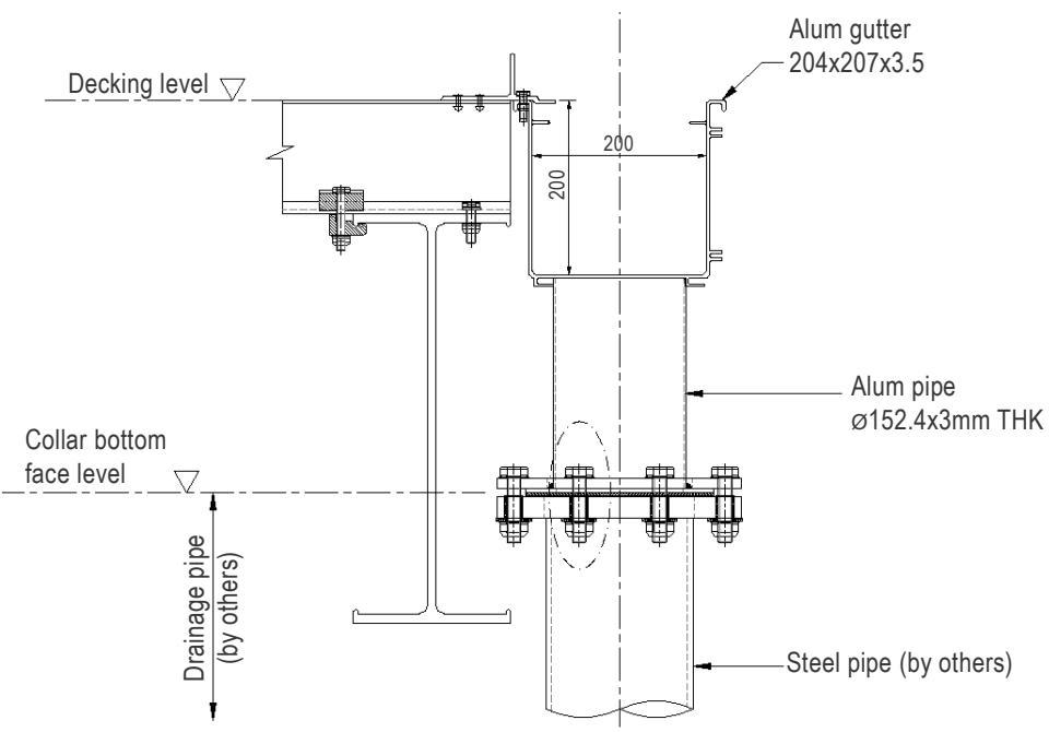
TYP. Gutter/Scupper detail
E) VERIFICATION THAT DISCHARGE OF GUTTER HEADER PIPES SUFFICIENT FOR RAINFALL OF120MM/HR:
Therefore, for discharge of 3 pipes, Q3 = 0.0472 m3/sect (discharge for 3 pipes)
Q3 = 2832 Litres / min
Q3 > Qr satisfactory
This shows that 3 gutter header pipes are already satisfactory to cater for the rainfall intensity flow, Qr.
Note: Vertical pipes considered for design = 6 nos. See below for the locations of each scupper.
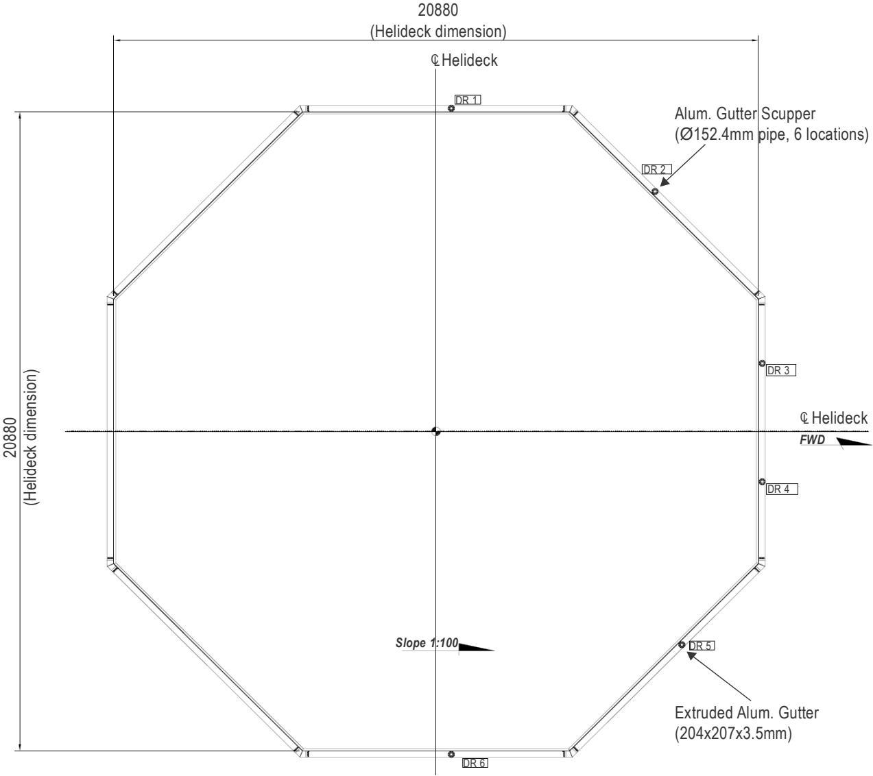
Aluminium Gutter Layout
F) COMPUTATION OF DISCHARGE CAPACITY OF THE GUTTER DRAINS:
Use Manning formula for steady uniform flow: Qd = (1/n) * (A * R^(2/3) * S^(1/2))
H = 0.20 m (cross sectional height of the gutter drains)
W = 0.20 m (internal width of the gutter drains)
A1 = 0.036 m2 (assumed only 90% of sectional area is full)
p = 0.56 m (wetted perimeter of the cross sectional area of
gutter, assumed only 90% effective)
R = A1/p = 0.064 m
n = 0.015 (aluminium material roughness based on
Manning's roughness coefficient)
S1 = 0.01 (Slope 1:100)
Qd1 = 0.038 m3/sec (for one way flow direction)
S2 = 0.001 (assumed to be almost flat)
Qd2 = 0.024 m3/sec (for two way flow direction)
By considering 3 Gutters effective at each flow side of decking edge, the total discharge, Qdt, will be;
Qdt = (Qd1)*(2 gutters) + (Qd2)*(1 gutter)
= 0.101 m3/sec
= 6078 Litres/min
G) TIME REQUIRED TO DISCHARGE ANY SPILLED FUEL IN THE HELICOPTER TANK:
V, Fuel capacity = 4.28 m3
Time = (V/Qt) = 0.70 mins. (Time required to discharge the fuel from
tank)
H) DISCHARGE CAPACITY REQUIRED TO FIREFIGHTING APPLICATION RATE OF 5.5 LITRES PER MIN PER SQ:
$$ \begin{array} { r l r } { \mathrm { Q d t a n d Q t } } & { { } > } & { \mathsf { Q m } , \mathsf { S a t i s f a c t o r y ! } } \end{array} $$
I) WORST CASE SCENARIO - COMBINATION OF RAINFALL, FUEL SPILLAGE & FIREFIGHTING APPLICATION:
$$ \begin{array} { r l r } { \mathsf { M i n . \ d i s c h a r g e \ r e q u i r e d \ p e r { \ m i n } } , } & { = } & { 2 4 4 8 \mathsf { l i f r e s / m i n } } \ & { } & { \mathsf { O r } + \mathsf { O m } } \end{array} $$
$$ \begin{array} { r l r } { \mathsf { Q d t a n d Q t } } & { { } > } & { \mathsf { Q r } + \mathsf { Q m } , \mathsf { S a t i s f a c t o r y ! } } \end{array} $$
The available discharge capacity for the fuel spillage,
$$ \begin{array} { l l l } { \mathsf { Q a } = \mathsf { m i n } ( \mathsf { Q d t } , \mathsf { Q t } ) - ( \mathsf { Q r } + \mathsf { Q m } ) } & { = } & { 3 2 1 5 \mathrm { ~ | i t r e s / m i n } } \end{array} $$
Time taken to discharge the fuel, V/Qa = 1.33 min
In conclusion, based on the calculations above, the gutters and downcomer are sized for their intended use.
PART II
ONSHORE HELIPORTS
Chapter 1
Historical Background
1.1 INTRODUCTION
1.1.1 Annex 14 — Aerodromes, Volume II — Heliports first became applicable on 15 November 1990, and includes specifications on the planning, design and operation of heliports. The applicability of visual aids is limited to operations at visual heliports.
1.1.2 Since the publication of the Heliport Manual (Doc 9261) in 1995, the perception of heliports as smaller versions of aerodromes with runways and associated surfaces has changed. The majority of heliports no longer have runway-type final approach and take-off areas (FATOs) and are not situated in large open areas; most are on small sites, located where the versatility of the helicopter permits operations inaccessible to fixed wing aircraft.
1.1.3 Heliports in congested areas have necessitated an elevation of the facilities to the tops of buildings to raise them above the obstacle environment. The lack of surface area on these elevated sites, has required a reassessment of the attributes of some defined areas resulting in the necessity for a solid surface being removed from some or transferred to others.
1.1.4 Due to these changes and others made to Annex 14, Volume II, a more detailed explanation of the evolving Standards and Recommended practices (SARPs) was necessary.
1.1.5 Since the development of helidecks and onshore heliports have become increasingly complex and the responsibility for such developments does not always reside with the same organization, each topic now has its own section in the manual.
1.2 SCOPE AND PURPOSE
1.2.1 Part II of this manual is complementary to the SARPs contained in Annex 14, Volume II.
1.2.2 Although the manual is primarily addressed to States and for heliports intended to be used by helicopters in international civil aviation, it can be used as a resource for all heliports and by all heliport designers and, when necessary, for helicopter operations conducted at such heliports.
1.2.3 The objective is to provide a common resource for heliport design and information for the qualification and training of inspectorate staff, as well as heliport and operational personnel.
1.2.4 Part II specifies the design process and, where necessary, the operational procedures that inform the minimum dimensions for the defined areas on the heliport. It provides a framework for the delivery of conformant heliports in future environments as well as means for adapting existing heliports due to changes in the local environment. The provision and procedures in this document do not relieve the end user of their responsibility to ensure compliance with Annex 14, Volume II and, to the extent necessary, Annex 6 — Operation of Aircraft, Part III — International Operations — Helicopters.
1.3 CONTENTS OF DOCUMENT
1.3.1 Introduction
Chapter 1 sets out the history, rationale and scope of Part II.
1.3.2 Site selection, management and heliport data
Chapter 2 provides guidance on the choice and development of heliport sites, including minimizing the effects of noise and pollution on surrounding conurbations, and safeguarding the surfaces outside the confines of the heliport. The training of inspectorate staff and the certification and subsequent management of facilities, including safety management systems, will be included in a future edition.
1.3.3 Physical characteristics of onshore heliports
1.3.3.1 Chapter 3 introduces the concept of defined areas as self-contained objects along with their attributes and associations, before examining each in the context of operations to and within them. It provides examples of how such defined areas may be grouped, collocated and coincidentally sited. It introduces Performance Class 1 profiles that have a significant bearing on the size and design of defined areas.
1.3.3.2 Appendices are further dedicated to the design helicopter and its critical elements, surface loading with particular emphasis on airworthiness standards and their implication to the defined areas, establishing the requirements for dimensions of the surfaces required for Performance Class 1 operations, and the introduction of clearways beyond the physical boundary of the heliport – on the surface, above, and below the level of the site.
1.3.4 Obstacle environment
Chapter 4 examines the requirement for obstacle surfaces and their application to normal and non-normal operations both with and without the use of Point in Space (PinS) procedures. Its appendix introduces guidance for elevating the clearway and surfaces above the obstacle environment, thus facilitating heliports in obstacle rich environments.
1.3.5 Visual aids
Chapter 5 contains guidance for marking and lighting of defined areas. It contains examples of lighting systems that are now, in preference, situated on the landing surface rather than providing illumination of these areas from the periphery. Its appendices contain examples of guidance systems, as well as an example of a specification for a hospital heliport lighting system.
1.3.6 Heliport emergency response
Chapter 6 addresses the two issues of heliport emergency planning and, where required, the provision of dedicated rescue and firefighting services. There are two Appendices: one providing a sample system for a task/resource analysis; and a second giving an insight into crashworthiness provisions for helicopters.
SITE SELECTION, MANAGEMENT AND HELIPORT DATA
2.1 SITE SELECTION AND MANAGEMENT
2.1.1 Site selection
General
2.1.1.1 Since helicopter operations can be provided in very close proximity to where there is often traffic, the selected site should be conveniently situated with regard to safety, ground transport access and adequate vehicle parking facilities.
2.1.1.2 To minimize noise disturbance, the ambient noise level should also be considered, particularly when near noise-sensitive buildings such as hospitals, schools and business premises and, especially in relation to areas beneath the approach and departure paths of helicopters.
2.1.1.3 Heliport design and location should be such that downwind operations are avoided and cross-wind operations are kept to a minimum (see Chapter 4, 4.1.1.9). These criteria should apply equally to surface level and elevated heliports.
2.1.1.4 Possible air traffic conflicts between helicopters using a heliport and other air traffic should be avoided. The need to provide air traffic control services may need to be examined.
2.1.1.5 For heliports used in Performance Class 2 (PC2) and 3 (PC3), the ground beneath the take-off climb and approach surfaces should permit safe one-engine-inoperative (OEI) landings or forced landings, during which injury to persons on the ground and damage to property are minimized and mitigated as needed. The provision of services in such areas should also minimize the risk of injury to the helicopter occupants. The main factors in determining the suitability of such areas will be the most critical helicopter type for which the heliport is intended and the ambient conditions.
2.1.1.6 The presence of large structures close to the proposed site may be the cause, in certain wind conditions, of considerable eddies and turbulence that might adversely affect the control or performance of the helicopters operating at the heliport. Equally, the heat generated by large chimneys under, or close to, the flight paths may adversely affect helicopter performance during approaches to land or climb out after take-off. It may be necessary to establish if such adverse conditions do exist and, if so, to determine possible mitigating and remedial action.
2.1.1.7 Other factors to be considered in the selection of a site are:
a) high terrain or other obstacles, especially power lines, in the vicinity of the proposed heliport;
b) existing development plans for the surrounding area; and
c) if PinS operations are planned, the availability of suitable airspace for approach and departure procedures.
2.1.1.8 The essential components of a heliport are areas suitable for the take-off and approach manoeuvre, lift off and touchdown, and parking.
2.1.1.9 A site should have a simple layout which combines defined areas that have common characteristics; such an arrangement will require the smallest overall area. When the characteristics or obstacle environment of a particular site do not allow such an arrangement, the components may be separated but must be connected to other areas by helicopter taxiways or air taxi-routes.
2.1.2 Surface-level heliports
2.1.2.1 When heliports are planned at high elevations or in places of high temperatures, the effects of minimized air density and high temperature result in reductions in both helicopter engine performance and rotor performance. In some helicopters, the power available may be reduced below that which is required for the helicopter to climb vertically out of the ground effect without considerably reducing the gross take-off mass.
2.1.2.2 As a helicopter gains forward speed, the mass airflow through the rotor disc increases up to a certain speed and enhances lift. In consequence, the power required for horizontal flight is reduced, thus releasing more of the power available to be used for the climb.
2.1.2.3 In the field of commercial helicopter operations, an operation cannot be considered economically viable if the take-off mass is reduced to less than 85 per cent of the maximum mass. To avoid this, it may be necessary to provide an area over which the helicopter can accelerate safely to its climbing speed before leaving the ground effect.
2.1.2.4 Table II-2-1 gives guidance on the length of surface that should be provided for helicopters with limited climbing power for a selection of altitudes and temperature conditions. In calculating the climbing speed, a maximum rotation angle of 10° should be considered commensurate with passenger comfort.
2.1.2.5 Helicopter flight manuals contain performance graphs which indicate combinations of forward speed and height above ground in which flight should be avoided since, in the event of engine failure, the probability of a successful forced landing is remote (see Figure II-2-1). Therefore, in order to provide the helicopter with an area over which it can safely accelerate to avoid these unsafe combinations, it may be prudent to facilitate the surfaces suggested in Table II-2-1.
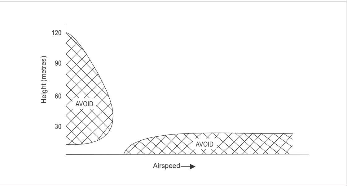
Figure II-2-1. HV Diagram
Table II-2-1. Acceleration distances required due to changes in altitude and temperature
| CLIMBINGSPEED | 40 kts | 50 kts | 60 kts | ||||||
| TEMPERATURE | ISA-15°C | ISA | 1SA+15°C | ISA-15°C | ISA | 1SA+15°C | 1SA-15°C | ISA | 1SA+15°C |
| HELIPORTELEVATIONfeet | ACCELERATION DISTANCE(METRES (FEET)) | ||||||||
| Sea level | 118(387) | 124(408) | 131(429) | 184(604) | 194(637) | 204(670) | 265(870) | 280(918) | 294(966) |
| 1000 | 121(398) | 128(420) | 135(442) | 190(622) | 200(656) | 210(690) | 273(895) | 288(945) | 303(995) |
| 2000 | 125(410) | 132(433) | 139(456) | 195(640) | 206(676) | 217(712) | 281(922) | 297(973) | 312(1 024) |
| 3000 | 129(422) | 136(446) | 143(470) | 201(659) | 212(696) | 223(733) | 290(950) | 306(1003) | 332(1 056) |
| 4000 | 132(434) | 140(459) | 148(484) | 207(679) | 219(717) | 230(755) | 298(978) | 315(1 033) | 332(1 068) |
| 5000 | 137(448) | 144(473) | 152(498) | 213(699) | 225(739) | 237(779) | 307(1 007) | 324(1 064) | 342(1 121) |
| 6000 | 141(462) | 149(488) | 157(514) | 220(721) | 232(762) | 245(803) | 316(1 038) | 335(1 098) | 353(1 158) |
| 7000 | 145(475) | 153(503) | 162(531) | 226(743) | 240(786) | 253(829) | 326(1 070) | 345(1132) | 364(1193) |
| 8000 | 149(490) | 158(159) | 167(548) | 233(766) | 247(811) | 261(856) | 336(1 103) | 356(1 067) | 375(1 231) |
| 9000 | 154(505) | 163(535) | 172(565) | 241(790) | 255(836) | 269(882) | 346(1135) | 366(1 202) | 387(1312) |
| 10000 | 159(521) | 168(552) | 178(583) | 248(815) | 263(863) | 278(911) | 358(1 174) | 379(1 243) | 400(1 312) |
2.1.3 Elevated heliports
Elevated heliports provide a range of safety and environmental benefits over heliports at ground level which include, but may not be limited to, improvements in aircraft and public security, a reduction in noise nuisance and downwash effects at ground level, and greater protection from new obstacles that inevitably will grow up from time to time in the congested areas of cities.
2.1.3.1 Design considerations — environmental effects
2.1.3.1.1 Purpose-built elevated heliports are relatively streamlined structures usually fabricated from aluminium or steel. In isolation, they would present little disturbance to the wind flow and helicopters would be able to operate safely to them in a (more or less) undisturbed airflow environment. However, difficulties can arise if the wind has to deviate around the nearby buildings resulting in areas of flow distortion and turbulent wakes.
2.1.3.1.2 An elevated heliport in a congested hostile environment of a city or town, even when placed at an elevation that is above all other surrounding buildings, may still suffer to some degree from its proximity to tall and bulky structures sited around the heliport. Designers should create heliport designs that are safe and friendly for helicopter operations and that minimize the environmental effects which could have a detrimental impact on helicopter operations.
2.1.3.1.3 While it is a desirable feature for the heliport to be elevated as high as possible, for a heliport sited 60 m (196 ft) or more above ground level, the regularity of helicopter operations may be adversely affected in low cloud base conditions. In locations where weather patterns are such that low cloud bases occur on a regular basis, a trade-off may need to be struck between the height of the heliport above surrounding structures and its absolute height above ground level.
2.1.3.1.4 It is possible that heliports installed on the roofs of buildings will suffer to some degree from their proximity to adjacent tall buildings; it is sometimes impractical to site the heliport above every other tall structure. Any tall structure above, or in the vicinity of, the heliport may generate areas of turbulence or sheared flow downwind of the obstruction and thus potentially pose a hazard to the helicopter. The less aerodynamic (streamlined) the shape of the obstruction, and the broader the obstruction is to the flow, the greater will be the severity of the disturbance. The effect reduces with increasing distance downwind from the turbulent source. Ideally, a heliport should be located at least 10 structure widths away from any upwind structure which has a potential to generate turbulence.
2.1.3.1.5 An elevated heliport on a building should be located at or above the highest point of the main structure. This will minimize the occurrence of turbulence downwind of structures that are on the building.
2.1.3.1.6 The heliport should be located so that wind from the prevailing directions carry turbulent wakes away from the helicopter approach path(s). To assess if this is likely to be an issue, a designer should overlay the predominant wind direction vectors over the centre of the heliport to assess the likely impact on helicopter operations.
2.1.3.1.7 It is recommended, where practical, that the touchdown and lift-off area (TLOF) be located over the corner of a building with as large an overhang as is practicable. In combination with an appropriate elevation and an essential air gap, the overhang will encourage the disturbed airflow to pass under the TLOF, leaving a relatively clean ‘horizontal’ airflow over the TLOF. It is further recommended that the overhang should be such that the centre of the TLOF is vertically above, or outboard of, the outside edge of the building’s superstructure.
2.1.3.1.8 The height of the heliport above ground level and the presence of an air gap between the TLOF and the supporting building are the most important factors in determining wind flow characteristics over and around the TLOF. In combination with an appropriate overhang, an air gap separating the heliport from the superstructure beneath will promote beneficial wind flow over the TLOF.
2.1.3.1.9 If no air gap is provided, wind conditions immediately above the TLOF could be severe, particularly if mounted on top of a large multi-storey building due to the slab-side effect. However, designing an air gap typically of between 3 m (10 ft) and 6 m (20 ft) will have the effect of removing obstructions in the airflow immediately above the TLOF. Heliports mounted on very tall accommodation blocks will require the largest clearances, while those on smaller blocks, and with a large overhang, will tend to require smaller clearances. A 3 m (10 ft) air gap is desirable, but for shallow superstructures of three storeys or fewer, a smaller air gap may be sufficient.
2.1.3.1.10 The air gap must be preserved throughout the operational life of the facility, and the area between the underside of the heliport and the superstructure of the building should not become a storage area for bulky items that might hinder the free-flow of air through the gap.
2.1.3.1.11 With respect to turbulence, the standard deviation of the vertical airflow velocity of 1.75 m/s should not be exceeded. Where this is significantly exceeded (i.e. where the limit exceeds 2.4 m/s), there is the possibility that operational restrictions may be necessary.
2.1.4 Heliport siting to minimize the effects on third parties
2.1.4.1 Integration of heliport traffic within airport terminal manoeuvring areas (TMA/TCA)
2.1.4.1.1 Helicopters can use steep climb angles during take-off manoeuvres. In addition, some procedures in the Rotorcraft Flight Manual (RFM) require helicopters to initially move upwards and backwards before transitioning into forward flight. These may cause an unexpected triggering of traffic advisory systems on board nearby aircraft, sometimes when flying well above the heliport area or even though the planned flight trajectory of the helicopter is intended to ensure that it remains separated from other traffic at all times.
2.1.4.1.2 Where heliports need to be located within the vicinity of large aerodromes, the siting and design of FATOs should be carefully considered to minimize the interactions between heliport traffic and pre-existing aerodrome traffic. An operational study of helicopter flight-path trajectories should determine whether conflict detection by on board traffic advisory systems or ground surveillance radars is likely to occur.
2.1.4.1.3 Where interactions cannot be avoided, coordination between the heliport and helicopter operators, as well as the relevant air traffic services, should determine the appropriate operational measures to ensure there is no conflict (i.e. there is compatibility) between the heliport and aerodrome traffic.
2.1.4.2 Wake vortex mitigation
2.1.4.2.1 Helicopters in flight generate a wake turbulence in the shape of two parallel and counter rotating vortices originating respectively from the left and right edges of the main rotor disk and trailing behind the helicopter along its flight path. As a general rule, wake vortices linger for approximately 2 minutes before decaying and sink slowly towards the ground at a rate of about 300 feet per minute. While there are no conclusive wake vortex models for rotorcraft, there is evidence that helicopters generate significantly more severe wake vortices than fixed wing aircraft of similar masses.
2.1.4.2.2 The siting of a heliport should therefore be such as to limit the wake turbulence encounter risk for aircraft operating from surrounding aerodromes, especially where the traffic-mix includes light aircraft which are especially vulnerable to wake vortices.
2.1.4.2.3 Where simultaneous independent operations of helicopters and other aircraft are considered, the siting of the FATO should allow for the minimum separations which would be required between the other aircraft and an aeroplane 10 times the weight of the considered helicopter.
2.1.4.2.4 Where the FATO cannot be sited to provide the desired separation between heliport traffic and traffic vulnerable to helicopter wake encounters, coordination between the heliport and helicopter operators, as well as the relevant air traffic services, should determine the appropriate operational measures to mitigate the wake turbulence encounter risks.
2.1.4.3 Rotor downwash considerations
2.1.4.3.1 When manoeuvring at slow speeds, especially during take-off and landing, helicopters generate significant rotor downwash extending out to a distance of 2 to 3 rotor diameters below the generating aircraft. This downwash produces effects comparable to high and gusty wind conditions which may cause light or insecure cladding and other light objects and structures to become detached.
2.1.4.3.2 The design of a FATO should minimize the exposure of persons or loose objects to the downwash of helicopters. Within a distance of 3 rotor diameters from the FATO, no loose objects or light cladding should be allowed in areas which might be overflown by helicopters at low level, and no non-essential personnel should be present in these areas during helicopter operations. The backwards or sideways initial climb phase of PC1 operations should also be considered when assessing areas sensitive to the potential exposure to helicopter rotor wash. Experience suggests, when adopting these procedures, the characteristics of the downwash may exhibit a hard jet on the surface, which though localized, can nevertheless be quite intense.
2.1.4.3.3 Provided the elements of the infrastructure surrounding the heliport are designed to withstand gusty conditions up to Beaufort scale 10/11, no extra measures should be required to protect the structure against regular planned helicopter operations.
2.1.4.4 Helicopter noise exposure mitigation
2.1.4.4.1 Helicopters generate high noise levels and, although most heliports are not intended to accommodate continuous traffic flows, the overflight of even infrequent helicopter operations can generate a significant disturbance to third parties.
2.1.4.4.2 Noise and nuisance can be minimized by locating the heliport on or near the highest part of the estate and by planning the flight paths to avoid unnecessarily low transits over sensitive areas.
2.1.4.4.3 Where heliports need to be located in cities or other inhabited areas, in order to mitigate the disturbance caused by helicopter noises, it is recommended the FATO and the take-off and approach procedures and paths be designed to limit the effective perceived noise in decibels (EPNdB) of the helicopters the heliport is intended for, to 60 dB calculated on the outside walls of residential buildings and 60 dB inside other buildings such as offices and facilities open to the public where noise disturbance is sensitive.
2.1.4.5 Fumes and air pollution
2.1.4.5.1 Helicopters may generate some fumes and emit various levels of pollutants depending on engines types and operational procedures. Newer generation helicopter engines tend to be cleaner but turbine engine operations, especially at low power settings may generate fumes and unpleasant hydrocarbon smells.
2.1.4.5.2 Ingestion of such effluents in air conditioning equipment of buildings surrounding a heliport can be avoided by careful positioning of air intakes with regard to their proximity to the heliport, and to prevailing wind directions. Design of exhausts in any case should cater for high winds and prevent ingestion from outside by means of over pressuring and fitment of cowlings.
2.1.4.6 Vibrations
2.1.4.6.1 Helicopters may generate vibration either through transmission of the engine and rotor mechanical vibrations or through the buffeting of the rotor airflow against surrounding horizontal or vertical building surfaces.
2.1.4.6.2 Vibration effects can be exacerbated by reverberation due to the pressure waves emitted by a helicopter reflecting off, and being amplified by, surrounding vertical surfaces.
2.1.4.6.3 The design of the heliport should minimize the risk of transmitting unwanted vibrations to nearby facilities e.g. a non-purpose-built heliport sited on top of a hospital where delicate surgical procedures are taking place. On an elevated purpose-built facility set above surrounding buildings, this effect is likely to be minimal, if it exists at all.
2.2 HELIPORT DATA
2.2.1 Aeronautical data
2.2.1.1 The specifications concerning the accuracy and integrity classification of heliport-related data are contained in the PANS-AIM (Doc 10066), Appendix 1.
2.2.1.2 Detailed specifications concerning digital data error detection techniques are contained in the PANS-AIM (Doc 10066).
2.2.2 Heliport dimensions and related information
The data specified in Annex 14, Volume II, Chapter 2.4, should be provided in the form and order specified in the PANS-AIM (Doc 10066), Appendix 3, AD 3. Heliports.
2.2.3 Declared distances
The declared distances specified in Annex 14, Volume II, and in the PANS-AIM (Doc 10066), Appendix 3, AD 3.13 are normally associated with a heliport with a runway-type FATO. For a heliport with other than a runway-type FATO, these should be provided in a modified form.
2.2.3.1 Take-off distance available (for helicopters)
2.2.3.1.1 For a runway-type FATO, the take-off distance available should be the length of the FATO, plus the length of any clearway provided. The clearway is measured from the end of the FATO as far as the nearest upstanding obstacle in the direction of take-off, within the required width.
2.2.3.1.2 For other than a runway-type FATO, a virtual clearway might be provided in accordance with Appendix D to Chapter 3. In this case, when the clearway is not at the elevation of the FATO, the origin of the clearway should be provided as a height above, or below, the elevation of the FATO. The take-off distance available should be the horizontal distance from the back of the FATO to the end of the clearway.
2.2.3.2 Rejected take-off distance available (for helicopters)
2.2.3.2.1 For a runway-type FATO, the rejected take-off distance available should be the length of the FATO.
2.2.3.2.2 For other than a runway-type FATO, the rejected take-off distance available should be the FATO dimensions. When the FATO is not coincidental with the TLOF, a note should be added to indicate that only the TLOF has a surface area suitable for a rejected take-off (see also Appendix C to Chapter 3).
2.2.3.3 Landing distance available (for helicopters)
The landing distance available should be the length of the FATO area plus any additional area declared available and suitable for helicopters to complete the landing manoeuvre from a height 15 m (50 ft) above the landing surface. When the FATO is not coincidental with the TLOF and does not have a (suitable) surface, a note should be added to indicate that only the TLOF has a surface area suitable for a OEI landing (see also Appendix C to Chapter 3).
2.2.4 Rescue and firefighting
It is recommended that information concerning the level of protection provided at a heliport for helicopter rescue and firefighting be made available. The level of protection, where appropriate, should be expressed in terms of the category of rescue and firefighting services as described in Annex 14, Volume II, Chapter 6, Table 6-1.
2.3 CERTIFICATION OF HELIPORTS
To be completed in due course.
2.4 SAFETY MANAGEMENT SYSTEM
To be completed in due course.
2.5 HELIPORT WINTERIZATION
2.5.1 Swirling snow raised by a helicopter’s rotor wash can cause the pilot to lose sight of the intended landing point and obscure objects that need to be avoided. The heliport should be designed to accommodate the methods and equipment used for snow removal. The heliport should allow the snow to be removed sufficiently so it will not present an obstruction hazard to the tail rotor, main rotor, or undercarriage and provide visibility of all required heliport markings and lights.
2.5.2 Heliports at which there is an expectation for helicopters to operate regularly in sub-zero conditions may wish to incorporate a heating system to prevent the build-up of snow and ice throughout the entire landing area.
2.5.2.1 Aluminium, widely used in the construction of purpose-built heliports, is known to be a good conductor of heat (having about three times the thermal conductivity of steel), and electrical heating cables can be integrated in the aluminium planking profiles (materials used for cabling should not have a detrimental effect on heliport surface friction and ideally should not protrude above surface level). In consideration of the poor thermal performance of concrete (low conductivity, high inertia), heat tracing electrical cables are not recommended for use with a concrete surface. An efficient electrical heat tracing system incorporated into the heliport design should remove or minimize the labour-intensive need to clear snow and ice manually.
2.5.2.2 Alternatively, heating of the operational zones may be achieved with systems that use hot liquids. To prevent icing of the surface, the temperature does not need to be more than 5°C. On elevated heliports, it is possible to obtain good results at low cost utilizing the liquid used for heating the building.
2.6 SAFEGUARDING OF HELIPORTS
2.6.1 The specifications in Annex 14, Volume II, Chapter 4, describe the airspace around heliports to permit safe helicopter operations and prevent, where appropriate State controls exist, heliports from becoming unusable by the growth of obstacles around them. This is achieved by establishing a series of obstacle limitation surfaces that define the limits to which objects may project into the airspace.
2.6.2 Safeguarding assesses the implications of any development being proposed within the vicinity of an established heliport to ensure, as far as practicable, that the heliport and its surrounding airspace is not adversely impacted by the proposal, thus ensuring the continued safety of helicopters operating at the location.
2.6.3 Safeguarding is the process by which the heliport operator can, in consultation with the local authority and within their capability, protect the environment surrounding the heliport from developments that have the potential to impact on the heliport’s operation and/or business.
2.6.4 Heliport safeguarding covers several aspects. Its purpose is to protect:
a) the airspace around a heliport to ensure no buildings or structures may cause danger to aircraft either in the air or on the ground. This is achieved through the provision of the ‘obstacle limitation surfaces’ (OLS)1;
b) all elements of heliport lighting by ensuring that they are not obscured by any proposed development and that any proposed lighting, either temporary or permanent, cannot not be confused for aeronautical ground lighting.
c) the heliport from any increased wildlife strike risk, in particular, bird strikes, which pose a serious threat to flight safety (e.g. the proximity of a garbage and waste disposal site);
d) heliport operations from interference by any construction processes through the production of dust and smoke, temporary lighting or construction equipment impacting on navigational aids; and
e) helicopters from the risk of collision with obstacles through appropriate lighting.
All the above should be taken into account by the heliport operator when assessing development proposals.
2.6.5 For the purposes of safeguarding, a layout plan should be provided showing key dimensions, such as heliport elevation, TLOF size, FATO size, safety area size, clearway(s), distance from safety area or clearway perimeter to property edges, and approach/departure paths showing locations of buildings, trees, fences, power lines, obstructions (including elevations), schools, places of worship, hospitals, residential areas, and other significant features.
2.6.6 The above mentioned layout plan should be shown together with transitional surfaces, virtual clearways and obstacle limitation surfaces, with the altitude of their origins if elevated.
2.6.7 All information should be displayed on a safeguarding map specified under the PANS-AIM (DOC 10066), Appendix 3 (AD 3.23 – Charts related to a heliport), or a topographical map provided for this purpose.
2.6.8 Appendix A to Chapter 2 provides a sample of an aviation safeguarding procedure.
2.7 INSPECTOR QUALIFICATIONS AND TRAINING
To be completed in due course.
Appendix A to Chapter 2
SAMPLE AVIATION SAFEGUARDING PROCEDURE
1. INTRODUCTION
1.1 Once a heliport has been established, the facility should be safeguarded against the growth of obstacles that could compromise and restrict the facility, or even prohibit its use due to the number of obstructions around the facility.
1.2 Without formal safeguarding arrangements in place, it is difficult to control the growth of obstacles beyond the boundary of the heliport. It is preferable to establish a formal safeguarding arrangement as described herein.
2. PURPOSE
Describes the process to follow to protect the heliport against the growth of obstacles.
3. RESPONSIBILITIES
3.1 The owner or operator of the heliport is responsible for:
a) providing and updating the safeguarding map and distribution lists;
b) ensuring that the landing site remains fit for purpose and safe for use by helicopter operators;
c) conducting a safeguarding assessment whenever a proposed development may impact the heliport;
d) notifying the helicopter operators whenever an unannounced object is constructed within 1.5 km of the heliport boundary; and
e) notifying the appropriate authority if an object (such as a crane) with a potential to be an obstacle to helicopter operations has been erected without prior knowledge, and request the issuance of a NOTAM by the appropriate authority.
3.2 Helicopter operators should be encouraged to respond to a safeguarding consultation by the owner or operator of the heliport and provide technical input into the heliport operator’s safety assessment.
3.3 Where formal safeguarding arrangements are in place, the local planning authority is responsible for consulting the owner or operator of the heliport whenever a development is being proposed within 1.5 km of the heliport.
4. INITIAL ACTIONS FOR SETTING UP A SAFEGUARDING ARRANGEMENT
4.1 Write or visit the local planning authority to discuss and agree on a safeguarding arrangement.
4.2 If appropriate, lodge a safeguarding map with the local planning authority to denote the areas of consultation. The safeguarding map should contain at least the boundary of the agreed safeguarding area, with an indication of the protected surfaces within that area.
4.3 Once agreed, request confirmation from the local planning authority that formal arrangements have been established.
5. CONDUCTING A SAFEGUARDING ASSESSMENT
The following procedures should be followed:
a) record all details received from the local planning authority or developer on Form 1 (see Form 1: Safeguard Assessment);
b) where possible, conduct a safeguarding assessment (in relation to the protected surfaces);
c) forward Form 1 to primary operators (including search and rescue (SAR)) using the heliport requesting urgent comment and objections;
d) respond to the application within a 21-day period;
e) where an objection has been identified, notify the local planning authority or developer as early as possible; and
f) where appropriate, request the local planning authority to confirm whether the objection has been upheld1.
FORM 1: SAFEGUARDING ASSESSMENT
| Hospital Name: | |||
| Heliport Type: Surface level / Mounded / Raised / Elevated (Strike-through as appropriate) | |||
| TYPE OF APPLICATION: | |||
| FULL | □ | DATE RECEIVED. | |
| OUTLINE | □ | DATE REPLIED. | |
| TEMPORARY CRANES* | □ | (Reply within 21 days) | |
| OTHER □ | |||
| *Notice to Airmen may be necessary (NOTAM) | |||
| BRIEF DESCRIPTION AND LOCATION OF DEVELOPMENT | |||
| Ordnance Survey Coordinates (Easting/Northings) | |||
| Height of Structure Above Ground Level | |||
| Height of Ground Level at proposed location | |||
| Overall maximum height of proposed structure | |||
| SUMMARY OF SAFEGUARDING ASSESSMENT: | |||
| FORWARDED TO HELICOPTER OPERATORS FOR COMMENT: YES NO□ | |||
| Note: Consultation should include the Search and Rescue Operator | |||
| NAME OF OPERATOR No 1: NAME OF OPERATOR No 2: | |||
| NAME OF OPERATOR No 3: | |||
| RESPONSE TO LOCAL PLANNING AUTHORITY/DEVELOPER | |||
| Objection No Objection No Objection but | |||
| □ | with comment □ | ||
| Additional Comment: | |||
| □ | |||
PHYSICAL CHARACTERISTICS OF ONSHORE HELIPORTS
3.1 GENERAL
3.1.1 Introduction
3.1.1.1 A heliport consists of a number of essential components or defined areas; these are the basic building blocks of the design process.
Note.— The inclusion in Annex 14, Volume II of an objective, attributes or detailed specifications does not imply that a defined area has to be provided.
3.1.1.2 Each defined area has an objective consisting of a statement (or series of statements) describing usage and limitations, attributes (without values or detailed specifications) and necessary associations. The attributes for any defined area have to be satisfied even when associated (collocated1 or coincidental2) with another defined area; however, the more stringent Standard will always apply. The value or range of values of an attribute is specified as the design helicopter3.
3.1.1.3 The principle of encapsulation (the black-box approach) is important to the design concept: each defined area is described complete with its attributes, allowing it to be positioned in isolation, or in combination with other defined or subsidiary areas without the need for tables specifying separation distances. Encapsulation provides flexibility in design and objects can be present on the boundary of any defined and associated subsidiary area.
3.1.1.4 In this section, defined areas, subsidiary areas, attributes, associations and the concept of the design helicopter are introduced. In subsequent sections, each defined area is examined in detail with respect to the challenges presented by real life operations. Chapter 3 is concluded with a number of appendices having relevance to more than one type of defined area.
3.1.1.5 Only helicopters with a single main rotor are considered in this chapter.
3.1.2 Defined areas
3.1.2.1 Defined areas are divided into six categories:
a) FATO;
b) TLOF;
c) helicopter stand;
d) helicopter taxiway;
e) ground taxi-route; and
f) air taxi-route.
3.1.2.2 In addition to the defined areas, there are subsidiary areas which also have objectives:
a) safety area;
b) helicopter clearway; and
c) protection area.
3.1.2.3 Where a defined area is coincidental or collocated with another (for example the FATO and TLOF, the stand and TLOF, the taxiway and taxi-route (ground or air)), the association is established in the objective.
3.1.2.4 The objective of each defined area is sufficiently flexible to allow methods of compliance that are suited to the operational requirements.
3.1.3 Attributes
The most important of the attributes are those of ‘containment’, and ‘surface condition’. Some attributes are common to a number of defined or subsidiary areas; for this reason, unless there are specific issues that are associated with a specific defined or subsidiary area, the attribute may not be further addressed in the dedicated section.
3.1.3.1 Containment
3.1.3.1.1 Containment is an attribute which affords protection to the helicopter and permits safe clearance from obstacles to be established. Containment is one of two types: undercarriage containment or helicopter containment.
3.1.3.1.2 Undercarriage containment means that all parts of the undercarriage will be within the boundary of the defined area, e.g. the TLOF, stand or taxiway. Undercarriage containment is specified only when contact with the surface is intended. Containment will be dependent upon the anticipated type of arrival4, the amount of permitted manoeuvring, and errors of positioning when touching down or when ground taxiing.
3.1.3.1.3 Helicopter containment means that all parts of the helicopter will be within the boundary of the defined area, e.g. the FATO, stand or taxi-route. Helicopter containment always includes the main rotor and furthest part of the tail section (which might be the tail rotor, fenestron, etc.). Containment will be dependent upon the anticipated type of arrival, the amount of permitted manoeuvring and errors of positioning.
3.1.3.1.4 If a defined area (such as a TLOF or taxiway) provides only undercarriage containment, it should be collocated with a defined area that provides helicopter containment (a FATO, protection area or taxi-route). This should be specified in the association.
3.1.3.2 Surface conditions
3.1.3.2.1 The surface condition is an attribute that establishes the type of surface and relationship to associated areas, permitted presence of essential objects, surface loading, surface friction, resistance to rotor downwash, durability, and required drainage. Periodic inspections should ensure that the surface continues to meet the objective.
3.1.3.2.2 The type of surface will be conditional upon the type of area or whether it is intended for the helicopter to touchdown. If there is no intention to touchdown, the question of whether a surface is solid or not is a choice for the designer or is driven by other considerations such as lack of available surface area. Where helicopter containment (and protection from objects) only is required, the defined area may be in, or extend into space. When two areas are collocated, and both are solid, they should be contiguous and flush with each other.
3.1.3.2.3 The presence of essential objects and their maximum dimensions is dictated by the use of the area.
3.1.3.2.3.1 On a surface where touchdown is intended, objects whose function requires them to be located there (such as marker-lights, nets, tie-downs, deck integrated firefighting (DIFF) nozzles, etc.) may be allowed if they do not exceed a height of 2.5 cm, have chamfered vertical edges, and are not regarded as a hazard (mainly to skidded helicopters) or as obstacles.
3.1.3.2.3.2 On a surface where touchdown is not intended in a defined or subsidiary area, essential objects consisting of visual aids such as lighting may be permitted. Their permitted dimensions will be conditional upon location. When they are within the area of the FATO, their dimensions will be more limited than within the safety area. In practice, the inner boundary of the defined area normally defines the location and maximum dimensions of most essential objects.
3.1.3.2.4 Surface loading5 ensures adequate surface strength to permit a helicopter to touchdown, park or ground taxi without damage to the surface or helicopter. Surface loading will be either static, where only the mass of the helicopter is considered, or dynamic, where the mass times acceleration (a force comprising multiples of mass) is considered.
3.1.3.2.4.1 Static loading is discussed in Appendix B to Chapter 3 and, for elevated heliports, expanded in 3.1.8.
3.1.3.2.4.2 Dynamic loading is associated with any touchdown on a TLOF, or movement on a stand or taxiway. Surface loading will vary with the transfer of kinetic energy and its magnitude will be dependent upon the type of arrival and touchdown, or movement on the surface that can be expected or anticipated (see Appendix B to Chapter 3). Dynamic loading can be considered in four categories (the first three address the arrival of the helicopter and the last, other traffic on the surface):
a) normal landing6: associated with the certification condition ‘limit load’ and should have no effect on serviceability;
b) hard/heavy landing7: associated with the certification condition ‘ultimate load’ likely to result in some damage to the undercarriage;
c) emergency landing8: associated with the ‘ultimate limit state’ having defined but arbitrary conditions; and
d) use by vehicles and equipment in the ground handling of the helicopter.
3.1.3.2.4.3 Within those four categories:
a) a normal landing is associated with an all engines operating (AEO) arrival, a rejected take-off or OEI landing in PC1, or engine failure in air taxi;
b) a heavy landing is associated with an engine failure from an approach in PC2 and PC3 when not exposed9; and,
c) an emergency landing is associated with an approach or departure in PC2 and PC3 when exposed.
3.1.3.2.4.4 The movement of personnel, vehicles and equipment used in the ground handling of helicopters should be considered. The surface loading might be higher than that required for the design helicopter depending on projected usage.
3.1.3.2.5 Durability of the surface is essential10. Traffic density must be considered to ensure that the condition of the surface remains as specified for the life of the facility (or the applicable maintenance period).
3.1.3.2.6 Resistance to rotor downwash is likely to be an issue on surfaces that are not paved.
3.1.3.2.6.1 Rotor downwash loads are approximately equal to the weight of the helicopter distributed uniformly over the disk area of the rotor which can be compared to generally high, gusty wind conditions. Tests have established that rotor downwash loads are generally less than the loads specified in building codes for snow, rain, or wind loads typically used in structural design calculations (AC 150/5390-2C).
3.1.3.2.6.2 Rotor downwash on unpaved surfaces could result in foreign object debris (FOD), injury to persons and damage to surrounding property. In order to prevent this, the surface should be treated to avoid break up resulting in debris that might be lifted and scattered by the downwash.
3.1.3.2.7 Friction to prevent the skidding of helicopters or slipping of personnel
3.1.3.2.7.1 The surface of the TLOF or stand should be skid-resistant to both helicopters and personnel, especially when the surface is wet. The surface should, if necessary, be rendered to provide additional friction, and all essential markings on the surface should be applied with non-slip material.
3.1.3.2.7.2 Whenever necessary, the heliport surface should be rendered so as to meet minimum friction coefficients (μ) acceptable to the appropriate authority, for example: not less than 0.6 inside the touchdown/position marking (TD/PM) circle and on the painted markings and 0.5 outside the TDPC.
3.1.3.2.7.3 A wide variety of suitable materials are commercially available and information on which system would be best applied in particular cases may be sought through an appropriate authority in each individual State. Guidance may also be given by the State on what minimum friction properties need to be achieved to ensure that a given surface is rendered skid-resistant to helicopters and is suitable for personnel using the heliport. The appropriate authority should advise how a heliport can be tested and re-tested to ensure compliance.
Note.— It is recognized that certain aluminium heliports (especially elevated heliports) contain holes in the topside construction for the rapid drainage of fluids, including fuel spills which could occur, for example, if a helicopter’s fuel system is ruptured by the impact of a crash. In these cases, particular care should be taken to assess the quality of skid-resistance prior to the heliport going into service.
3.1.3.2.8 Required drainage. The slopes on the solid defined areas (or the surface itself) should be sufficient to prevent the accumulation of water or fuel on the area and allow rapid and effective drainage, but be within the sloping ground limitations of the design helicopter. The minimum slope of the surface should be in excess of 0.5 per cent. However, it should not exceed the value(s) specified for the defined area. The slope should be made without local indents to avoid ponding and should be such that the landing skid can lie as flat as possible on the surface. Sufficient ground stability of the helicopter should be achieved to avoid potential collisions of the tail and tail rotor with the surface.
3.1.3.2.9 Safety devices around an elevated heliport
3.1.3.2.9.1 Personnel protection safety devices such as perimeter safety nets or safety shelves should be installed around the edge of the elevated heliport, or a surface level heliport where there is a risk of persons falling11, except where structural protection already exists. They should not exceed the height of the outboard edge of the TLOF/FATO to avoid presenting a hazard to helicopter operations. The load bearing capability of the safety device should be assessed fit for purpose by reference to the shape and size of the personnel that it is intended to protect (see 3.1.3.2.9.5).
3.1.3.2.9.2 Where the safety device consists of perimeter netting, this should be of a flexible nature and be manufactured from a non-flammable material, with the inboard edge fastened just below the edge of the TLOF/FATO. The net itself should:
a) extend in the horizontal plane beyond the edge of the TLOF/FATO to the distance required by State rules (e.g. EN 1263-1 and EN 1263-2) and in any case to at least 1.5 m;
b) be arranged with an upward slope of approximately 10°12,13; and
c) not act as a trampoline but exhibit properties that provide a hammock effect to securely contain a person falling or rolling into it, without serious injury.
3.1.3.2.9.3 When considering the securing of the net to the structure and the materials used, each element should meet adequacy of purpose requirements, particularly that the netting should not deteriorate over time due to prolonged exposure to the elements, including ultraviolet light.
3.1.3.2.9.4 Perimeter nets may incorporate a hinge arrangement to facilitate the removal of sacrificial panels to allow for periodic testing.
3.1.3.2.9.5 A safety net support assembly and its fixings to the heliport primary structure should be designed to withstand the static load of the whole support structure, the netting system and any attached appendages plus at least 125 kg load imposed on any section of the netting system (equivalent to a body falling onto the net from heliport level).
3.1.3.2.9.6 Where the safety device consists of safety shelving rather than netting, the construction and layout of the shelving should not promote any adverse wind flow issues over the FATO, while providing equivalent personnel safety benefits, and should be installed to the same minimum dimensions as the netting system, beyond the edge of the TLOF/FATO. It may also be further covered with netting to improve grab capabilities.
3.1.4 Associations
3.1.4.1 An association establishes the dependency between defined areas and defined and subsidiary areas. When an association is specified in the objective, compliance is necessary to ensure safety.
3.1.4.2 The most common use of an association is to ensure that defined areas are collocated. For example, the TLOF provides containment only for the undercarriage to ensure that the whole aircraft is contained; the TLOF is associated with a FATO or stand.
3.1.4.3 Similarly, in order to reduce the risk of damage to the helicopter straying outside the boundary of the FATO by the effect of turbulence or cross winds, errors in positioning or mishandling, the FATO is associated with a safety area.
3.1.5 The design helicopter
3.1.5.1 The introduction of the concept of a design helicopter permits a simplification of the process for establishing the limiting dimensions of defined areas.
3.1.5.2 When designing the heliport, the design helicopter having the largest set of dimensions and the greatest maximum take-off mass (MTOM) should be established. Although this might be informed by consideration of a particular type of helicopter, the resulting virtual type should consist of a set of limiting values from the population of helicopters for which the heliport has been designed (a full discussion of the concept of the design helicopter and its critical design elements can be found in Appendix A to Chapter 1).
3.1.5.3 The designer and heliport user should be assured that when a helicopter is within the D-value and maximum allowable mass (promulgated, and in most cases displayed on the FATO) and is operated in accordance with normal practices, all defined areas will be safe to use.
3.1.6 The manoeuvring helicopter
For heliport design, the manoeuvring helicopter is a determining factor in establishing the minimum dimensions of most defined areas. Relevant sections address the issue of manoeuvring from the perspective of an approach to a FATO, or air and ground taxiing. However, a defining factor common to a number of areas is the turning manoeuvre, both in the hover and on the ground. For a discussion of the minimum dimension for turning in the hover and turning on the ground see Appendix A to Chapter 3, 3.5.
3.1.7 Designs with mixed surfaces
3.1.7.1 Sometimes the application of the objective or attributes for a defined area is complicated by availability of surface area. For example, a heliport may have a defined or subsidiary area wholly or partially projecting into space. This is more likely to apply to an elevated heliport rather than one on ground level.
3.1.7.2 This might result in a defined or subsidiary area surface that is partially solid and partially in space. Where this is the case, the part solid surfaces of collocated areas should be contiguous and flush.
3.1.8 Structural design of heliports
3.1.8.1 The heliport should be designed for the design helicopter, but should also consider other types of loading such as personnel, freight, snow, refuelling equipment, etc. For the purpose of design, it should be assumed that the helicopter will land on two main wheels, irrespective of the actual number of wheels in the undercarriage, or on two skids if they are fitted. The loads imposed on the structure should be taken as point loads at the wheel centres or contact area of the skids (see also Appendix B to Chapter 3).
3.1.8.2 An elevated heliport should be designed for the more conservative condition derived from consideration of Case A – Helicopter on landing (3.1.8.2.1) and Case B – Helicopter at rest (3.1.8.2.2).
3.1.8.2.1 Case A — Helicopter on landing
An elevated heliport should be designed to withstand all the forces likely to act when a helicopter lands. The load and load combinations to be considered should include:
a) Dynamic load due to impact on touchdown.
This should cover both a normal landing and an emergency landing. For the former, an impact load of 1.5 x MTOM of the design helicopter should be used, while for an emergency landing an impact load of 2.5 x MTOM should be applied in any position on the TLOF , together with the combined effects of b) to g) inclusive. The emergency landing case should govern the design of the structure.
b) Sympathetic response of the heliport.
After considering the design of the heliport structures’ supporting beams and columns and the characteristics of the design helicopter, the dynamic load (see a) above) should be increased by a suitable structural response factor (SRF) to account for the sympathetic response of the heliport structure. The factor to be applied for the design of the heliport framing depends on the natural frequency of the surface structure. Unless specific values are available based upon particular undercarriage behaviour and deck frequency, a minimum SRF of 1.3 should be assumed.
c) Over-all superimposed load on the heliport.
To allow for snow load, personnel, freight and equipment loads, etc., in addition to wheel loads, an allowance of 0.5 kilonewtons per square metre (kN/m2) should be included in the design.
d) Lateral load on the supports.
The heliport and its supports should be designed to resist concentrated horizontal imposed actions equivalent to 0.5 x maximum take-off mass (MTOM) of the design helicopter, distributed between the undercarriages in proportion to the applied vertical loading in the horizontal direction that will produce the most severe loading for the structural component being considered.
e) Dead load of structural members.
This is the normal gravity load on the element being considered.
f) Wind actions on the heliport.
Wind actions on the structure should be applied in the direction, which together with the horizontal impact actions, produce the most severe load case for the component considered. The wind speed to be
considered should be that restricting normal (non-emergency) helicopter operations at the landing area. Any vertical up and down action on the heliport structure due to the passage of wind over and under the FATO/TLOF should be considered.
g) Punching shear.
A check should be made for the punching shear from a wheel of the landing gear, or skid, with a contact area of 65 x 103 mm2 acting in any probable location. Particular attention to detailing should be taken at the junction of the supports and the surface.
3.1.8.2.2 Case B — Helicopter at rest
In addition to Case A above, an elevated heliport should be designed to withstand all the applied forces that could result from a helicopter at rest; the following loads should be taken into account:
a) Imposed load from helicopter at rest.
All parts of the heliport should be assumed to be accessible to helicopters and should be designed to resist an imposed (static) load equal to the MTOM of the design helicopter. This load should be uniformly distributed between all the landing gear and applied in any position so as to produce the most severe loading on each element considered.
b) Overall superimposed load.
To allow for personnel, freight, refuelling equipment and other traffic, snow and ice, and rotor downwash effects etc., a general area-imposed action of 2.0 kN/m2 should be added to the surface.
c) Horizontal actions from a tied down helicopter including wind actions.
Each tie-down, where provided, should be designed to resist the calculated proportion of the total wind action on the design helicopter imposed by a storm wind with a minimum one-year return period.
d) Dead load.
This is the normal gravity load on the surface being considered and should be regarded to act simultaneously in combination with a) and b).
e) Wind actions on the heliport.
Wind loading should be allowed for in the design of the heliport. The 100-year return period wind actions on the heliport should be applied in the direction which, together with the imposed lateral loading, produces the most severe load condition on each structural element being considered.
3.2 FATO
The FATO is an area over which a helicopter completes the approach manoeuvre to a hover or landing or commences the take-off. All approaches terminate at the FATO and all departures start there.
3.2.1 GENERAL
Recalling the definition of FATO, there are various types, each characterizing ‘completed’ from a different perspective; some examples are:
a) A PC2/3 FATO with an aiming point: an approach that is ‘completed’ with a hover (see Figure II-3-1);
b) A PC2/3 FATO with a TLOF: an approach which is ‘completed’ with a normal touchdown (see Figure II-3-2);
c) A PC1 FATO with a declared RTOD: an arrival (approach or rejected take-off) that may be ‘completed’ with a OEI touchdown (which may, or may not, include a run-on landing (see Figure II-3-3)); and
d) A PC1 FATO without a declared RTOD: an arrival (approach or rejected take-off) that may be ‘completed’ with an OEI touchdown (without a run-on landing (see Figure II-3-4 and Figure II-3-5)).
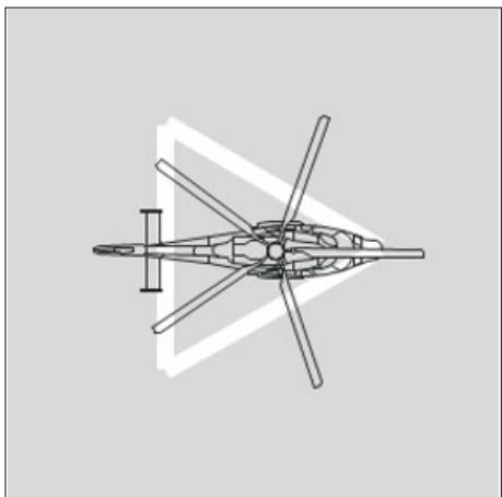
Figure II-3-1. PC2/3 FATO with an aiming point marking
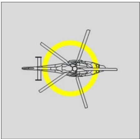
Figure II-3-2. PC2/3 FATO with a TLOF
3.2.2 FATO Attributes — Containment
3.2.2.1 PC2/3 FATO
3.2.2.1.1 Containment in a PC2/3 FATO is based on the space to transition to the hover from an approach and the subsequent necessity to manoeuvre; it is directly related to Design D.
3.2.2.1.2 Under normal operating conditions, the transition to a hover from an approach, without turns, can be contained within 1.5 x helicopter widths and 1.5 x helicopter lengths.
3.2.2.1.3 As indicated in Appendix A, 3.5.1, the space required for axial turns in the hover is 1.5 x Design D.
3.2.2.1.4 Based on the principles above, the minimum dimension of a FATO for unrestricted operations in PC2/3 is 1.5 x Design D. This dimension should be sufficient to provide containment of a helicopter during normal approach, departure and hover manoeuvres.
3.2.2.1.5 When there is a restriction on the direction of arrival, departure, touchdown and manoeuvring, the width of the FATO may be reduced to 1.5 x helicopter widths. Before this reduction is applied, it will be necessary to establish how the restriction on manoeuvring is to be marked and promulgated.
3.2.2.2 PC1 FATO
3.2.2.2.1 The dimension of the PC1 FATO, providing containment for operation in PC1, is not directly related to Design D but to adequate provision of space for the rejected take-off or OEI landing (see Appendix C to Chapter 3). Nevertheless, the minimum dimension for a PC1 FATO is set to 1.5 x Design D (as for PC2/3 and for the same reasons); operation in PC2/3 may be possible depending on the heliport use and limitations.
3.2.2.2.2 When considering the amount of area to be set aside for the FATO, it is important for the designer to consider the range of Category A procedures that could be employed before making a final determination. As this is a function more related to operations than heliport design, it may be necessary to seek guidance from operational experts.
3.2.2.2.3 The size of the rejected take-off area will vary with the type of procedure employed; the ‘clear area’ procedure 14 (Figure II-3-3) will require a longer FATO but should generally permit higher masses than ‘short field’ (Figure II-3-4) or ‘helipad’ (Figure II-3-5).
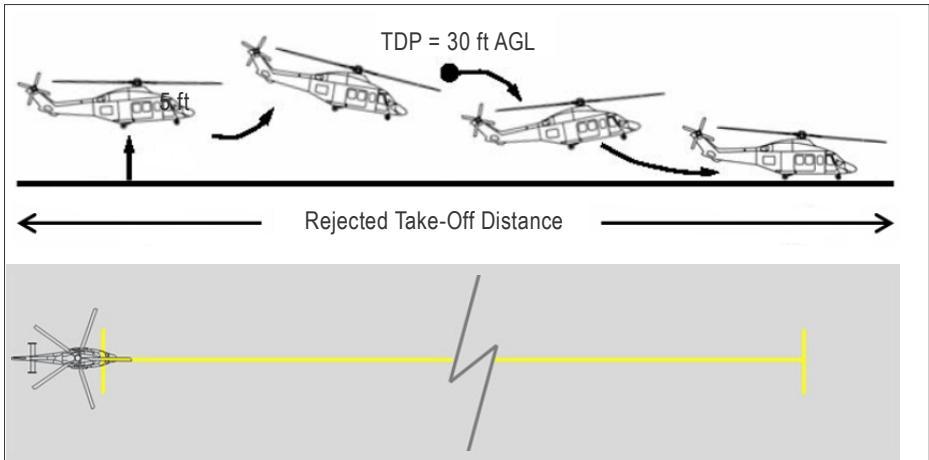
Figure II-3-3. PC1 (runway) FATO with a declared RTOD
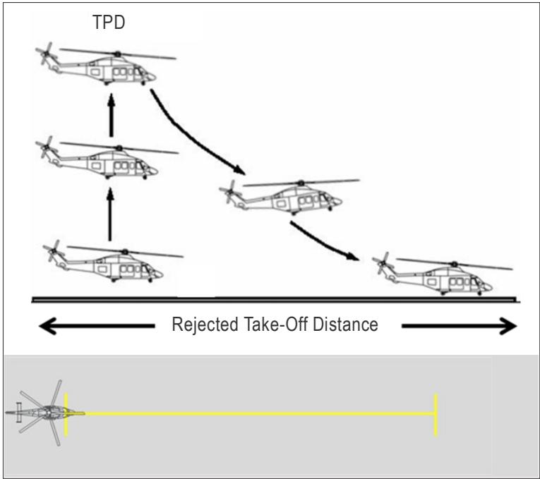
Figure II-3-4. PC1 (short field) FATO with or without a provided RTOD
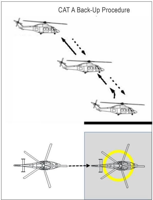
Figure II-3-5. PC1 (helipad) FATO without a declared RTODRH15
3.2.2.2.4 For a heliport designed for any specific type of PC1 procedure, the size of the FATO is important because the larger it is, the greater the population of helicopters able to use it. It should not be assumed that the reject distance for a large helicopter is greater than that for a smaller one. Failing to take this into consideration might result in an operational limitation for some helicopters that are within the D-Value and Maximum Allowable Mass but cannot operate within the declared distances of the heliport. This is more likely to occur with the helipad than the clear area procedure.
3.2.2.2.5 For PC1 operations, the rejected take-off distance required (RTODRH, provided in the RFM) should be less than or equal to the rejected take-off distance available (RTODAH, declared by the heliport operator) as shown in Figure II-3-6.
3.2.2.2.6 For all PC1 heliports, the FATO includes the RTOD: for the clear area procedure, the RTOD will be declared distance; for the helipad procedure, there will be no declared RTOD, only a FATO. When promulgating a declared distance, the relevance must be made clear.
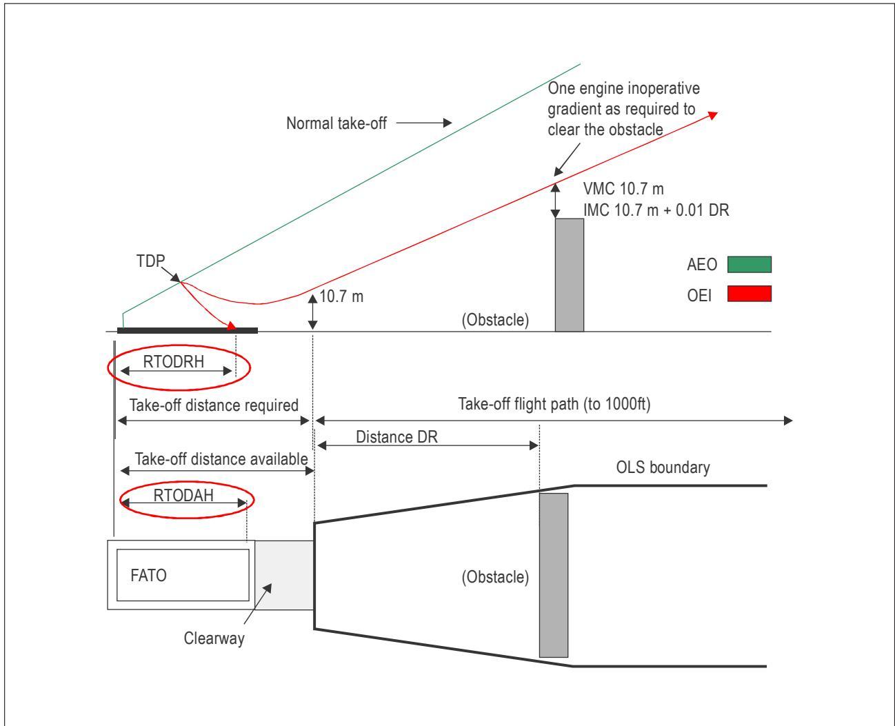
Figure II-3-6. Relationship between RTODRH and RTODAH (operational limitation)
The RTOD in the RFM or Category A supplement (see Appendix C to Chapter 3)
3.2.2.2.7 For most clear area procedures, the RTOD with complete helicopter containment will be provided in the Category A Supplement; in this case, the FATO will be coincidental with the TLOF. However, that is not always the case and it may be necessary to check with the manufacturer that full containment in accordance with the guidance has been provided.
3.2.2.2.8 A reasonable pointer to the presence of doubt is when the drawing in the RFM does not appear to cover the front part of the rotor and rear part of the helicopter; the indicative drawing appears only to show distance with respect to a reference point on the helicopter; or another term is used instead of RTOD.
3.2.2.2.9 When the RTOD with complete containment is not provided, adding 1 x Design D to the RFM dimension should provide a dimension that includes containment.
The absence of RTOD for the short field procedure
3.2.2.2.10 RTOD is not a term that is usually associated with the short field procedure. Any number of alternative terms may be in use – none of which is likely to have a meaning in regulatory language. In the absence of certainty, adding 1 x Design D to the RFM dimension will ensure containment.
The absence of RTOD for the helipad procedure
3.2.2.2.11 RTOD is a term that is almost never seen in the RFM for the helipad procedure. The term that is most often used is ‘the minimum elevated heliport size demonstrated’ (or another term approximating to that meaning). This term indicates that the dimension of the surface area (together with the necessary visual cues) only has been demonstrated and provided.
3.2.2.2.12 It may not be easy to establish the limiting dimension unless the heliport designer (or relevant subject matter expert) has surveyed, or is familiar with, all types that are likely to use the heliport. It would be wrong to assume that the declared dimension for a large helicopter will be greater than that for a smaller one.
3.2.2.2.13 When the limiting dimension has been established, if it is based upon ‘the minimum elevated heliport size demonstrated’, adding 1 x Design D to the ‘the minimum … sizes demonstrated’ will ensure containment.
3.2.3 FATO Attributes — Surface conditions
3.2.3.1 The requirement for a solid surface was removed from the FATO in Amendment 9 to Annex 14, Volume II. It is now unspecified and left to the designer. Where, as in 3.2.1 (b) to (d) a touchdown is expected, there will be a requirement for a TLOF and surface conditions will be specified there.
3.2.3.2 When the FATO is solid and not collocated with a TLOF, the surface should not present a hazard for a forced landing.
3.2.3.3 When the FATO is collocated with a TLOF, the designer should ensure that:
a) when solid, the FATO has a surface that is contiguous and flush with the TLOF. Although not intended for the placement or movement of a helicopter undercarriage on it, the FATO should have a surface that permits the movement of personnel, vehicles and equipment used in the loading, unloading or ground handling of the helicopter. The overall slope in any direction on a solid FATO should not exceed 2 per cent except for elongated FATOs. This should enable sufficient drainage;
b) the plane of the FATO should extend horizontally from the lowest elevation of the edge of the TLOF; and
c) essential objects consisting of visual aids such as lighting and firefighting systems may be contained within the boundary of the FATO. As it is likely that the tail rotor will traverse above such systems, they should not exceed a height of 5 cm above the plane of the FATO.
3.2.3.4 The removal of the requirement for a surface permits the use of a virtual FATO for operations in PC2/3 when its location is obvious and therefore does not need to be marked, such as a virtual FATO over water alongside a pier containing one or a number of stands. A helicopter could arrive to the hover alongside the pier before moving (air transiting) to one of the stands. The dimensions of the FATO should enable containment without markings. This type of operation is similar to that for offshore installations where the approach is normally to the side of the helideck before transitioning over the deck to land.
3.2.4 FATO associations and subsidiary areas
3.2.4.1 Safety area
3.2.4.1.1 The purpose of the safety area is to provide an extension to the FATO to compensate for errors of manoeuvring under challenging environmental conditions.
3.2.4.1.2 Containment. The safety area extends outwards from the periphery of the FATO for a fixed distance of the greater of 3 m or 0.25 Design D. Because it is fixed distance, it is imperative that the helicopter is not deliberately displaced from the TD/PM because it could result in the loss of containment shown in Figure II-3-7.
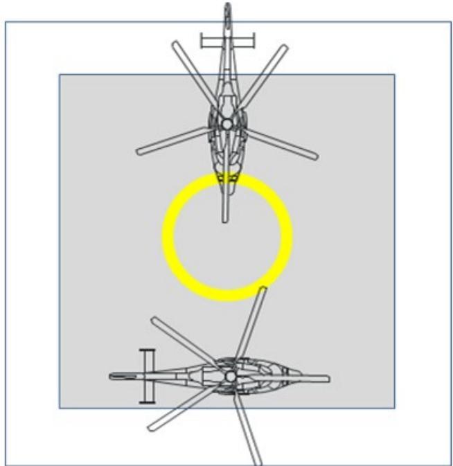
Figure II-3-7. Deliberate Misplacement within the FATO
3.2.4.1.3 Surface conditions. Surface conditions of the safety area are similar to those for the FATO as stated in 3.2.3. Essential objects such as visual aids and firefighting systems may be contained in the safety area to a height specified in Annex 14, Volume II. It is likely that such objects, which may be larger than those permitted in the FATO, will be located at, or just within, the inner boundary of the safety area.
3.2.4.1.4 The surface of a solid safety area should not exceed an upward slope of 4 per cent outwards from the edge of the FATO.
3.2.4.2 Protected side slope
3.2.4.2.1 For a visual heliport, or a heliport with a PinS approach procedure without a proceed visually instruction, there is no requirement for a transitional surface; in the absence of any further provisions, this would allow unlimited obstacles at the boundary of the safety area.
3.2.4.2.2 The protected side slope is intended to address this by providing a protected surface to a distance (and height) of 10 m (33 ft) rather than the 45 m (150 ft) of the transitional surface. Although the standard requires a protected side slope only on one side of the FATO, it would be preferable for the designer to provide side slope protection around all those parts of the FATO not covered by the obstacle limitation surfaces (take-off climb/approach surface), in accordance with Annex 14, Volume II, 3.1.14.
3.2.4.2.3 The FATO may be of any shape, and even though the protected side slope extends from the safety area, designers should be aware that, as shown in Figure 4-1 of Annex 14, Volume II, there might be small spaces between the take-off climb and approach surfaces and safety area; these should meet the requirement for the safety area and not the protected side slope.
3.2.4.2.4 Where take-off climb and approach surfaces are not diametrically opposed, the protected side slope should cover the whole of the area between the obstacle limitation surfaces. This may sometimes extend beyond 180⁰.
3.2.4.3 Helicopter clearway
3.2.4.3.1 The helicopter clearway, when provided, extends beyond the FATO, to permit a departing helicopter to accelerate in near level flight to achieve a safe climbing speed.
3.2.4.3.2 The length of the helicopter clearway should permit the achievement of the TODRH conditions, i.e. Vtoss and a positive rate of climb (+ROC), 10.7 m (35 ft) above the elevation of the helicopter clearway, at or before the outer boundary. The width of the helicopter clearway should be the specified width or diameter of the FATO plus the safety area or the reference circle (see Chapter 4, 4.1.1.8).
3.2.4.3.3 For operations in PC1, the TODRH should be equal to or less than TODAH, as shown in Figure II-3-8. Annex 6, Part III, permits an alternative to this when, following an engine failure, the helicopter is able to clear all obstacles in the continued take-off path by a vertical margin of 10.7m (35ft) (see Figure II-3-9). This alternative can be facilitated with the use of a virtual clearway (see Appendix D to Chapter 3) and appropriate procedures (see Appendix A to Chapter 4).
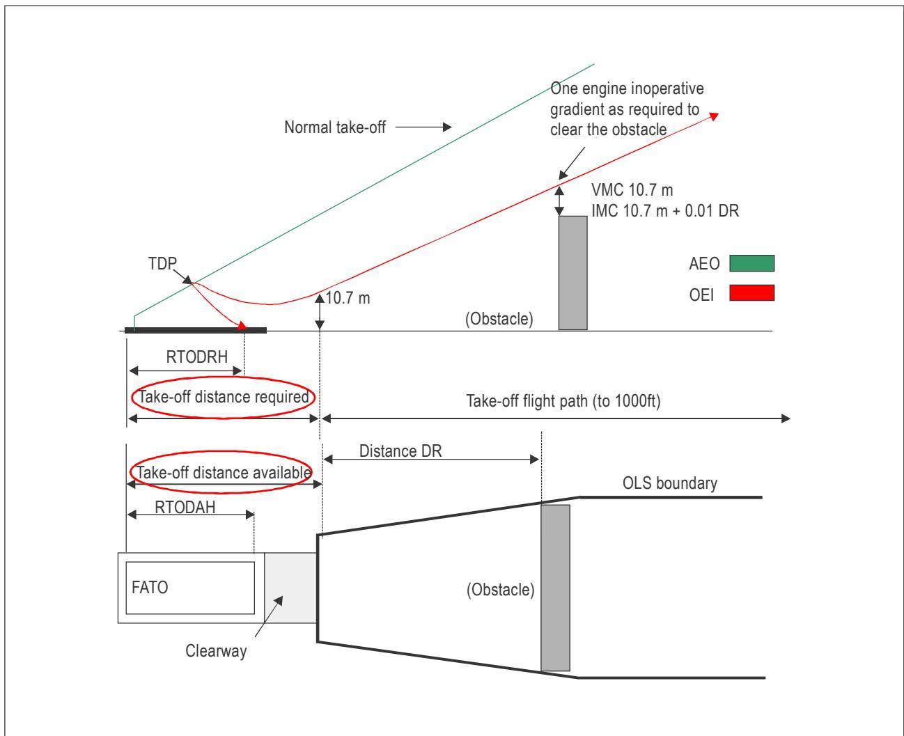
Figure II-3-8. Relationship between TODRH and TODAH (operational limitation)
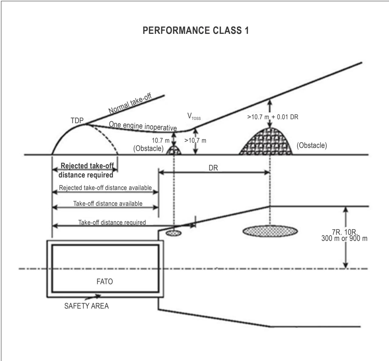
Figure II-3-9. Alternative procedure from Annex 6, Part III
3.2.4.4 Back-up area
3.2.4.4.1 A back-up procedure, i.e. without a lateral component, is one of the PC1 helipad profiles provided in RFMs, along with the dimensions of the backup area. The back-up area should consist of two elements: an ascent/descent path/surface and an obstacle limitation surface (see Figures II-3-10 to II-3-12). The dimensions of these are normally contained in tabular form in the Category A supplement of the RFM.
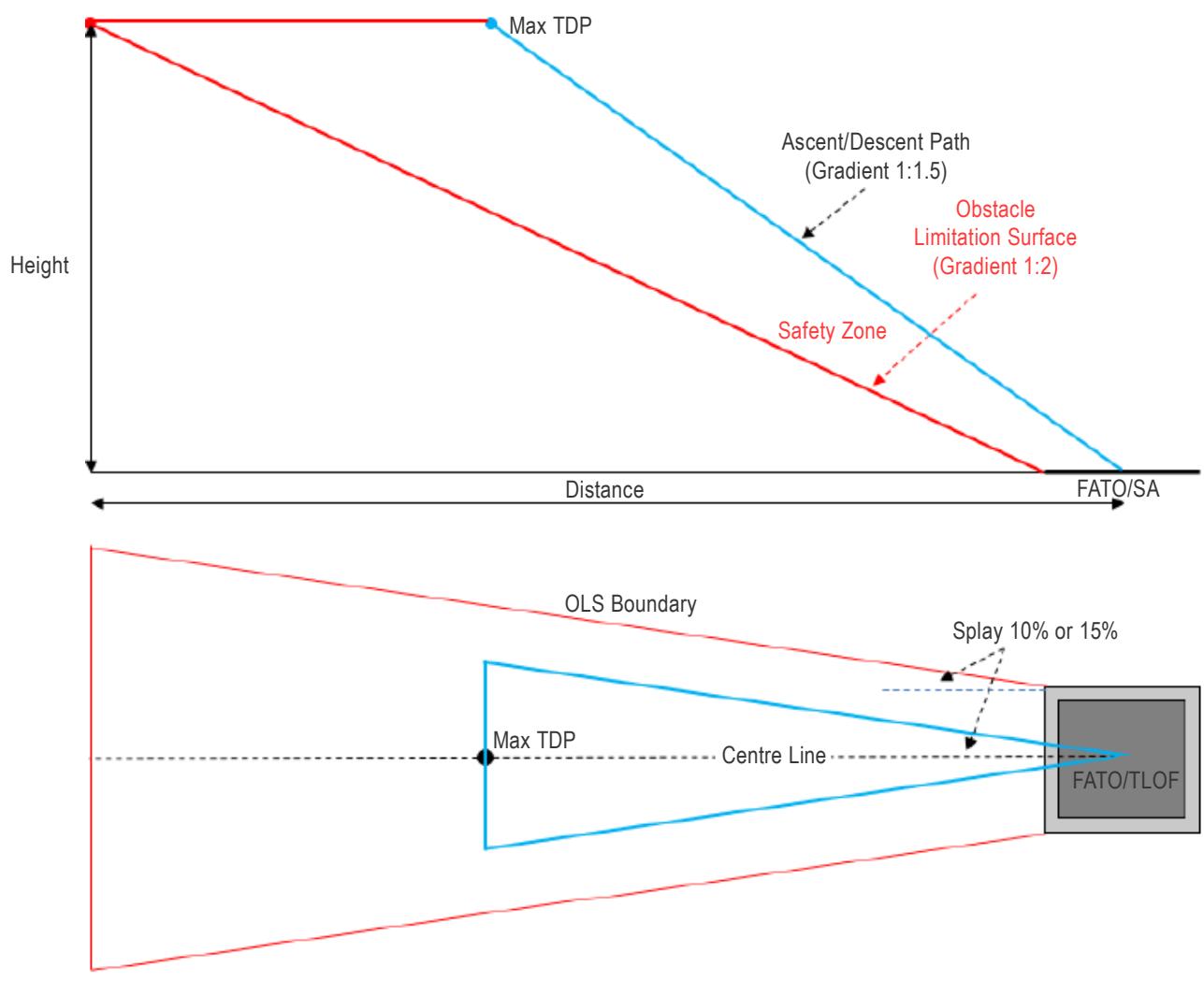
Figure II-3-10. Back-up area
3.2.4.4.2 The ascent/descent path/surface: the path of the helicopter in the back-up procedure. It represents:
a) the AEO climb to the TDP;
b) the OEI descent to the FATO following the failure of an engine before reaching the TDP;
c) where the landing decision point (LDP) is sited coincidentally with the TDP: the AEO, or if an engine fails at or after reaching the LDP the OEI, descent to the FATO.
3.2.4.4.2.1 The characteristics should be:
a) a sloping inverted isosceles triangle with its vertex at the centre of the TLOF, legs splayed 10 per cent (day) or 15 per cent (night) either side of the centre line of the FATO, and its base at the highest projected TDP for the procedure; and
b) a slope, measured in the vertical plane containing the centre line, allowing use by representative types using the PC1 heliport; a gradient of 1:1.5 is recommended.
3.2.4.4.3 The obstacle limitation surface is the boundary of the area that is obstacle-free which, when used in conjunction with the defined ascent/descent path/surface, should provide clearance from obstacles.
3.2.4.4.3.1 The characteristics of the obstacle limitation surface should be:
a) an inner edge horizontal and equal in length of the specified width of the FATO plus the safety area, perpendicular to the centre line and located at the edge of the safety area. The elevation of the inner edge should be the elevation of the safety area at the point on the inner edge that is intersected by the centre line of the obstacle limitation plane;
b) two side edges originating at the ends of the inner edge diverging uniformly at a specified rate from the vertical plane containing the centre line of the FATO (the specified rate is 10 per cent for day operations and 15 per cent at night);
c) an outer edge horizontal and perpendicular to the centre line at a specified height above the elevation of the FATO (the highest TDP for the procedure); and
d) a slope, measured in the vertical plane containing the centre line, related to the ascent/descent path/surface, allowing adequate clearance from obstacles; a gradient of 1:2 is recommended.
Note.— The divergence between the slope of the ascent/descent path and the slope of the obstacle limitation surface should be at least 12.5 per cent.
3.2.4.4.4 Where the back-up area overlays the take-off climb/approach surface, no further provision by the heliport designer should be necessary. Where the back-up area does not overlay the take-off climb/approach surface, a generic ascent/descent path/surface and obstacle limitation surface should be provided.
3.2.4.4.5 When the PC1 procedure includes a lateral element, the ascent/descent surface and obstacle limitation surfaces should be as shown in Appendix A to Chapter 4, 2.1.
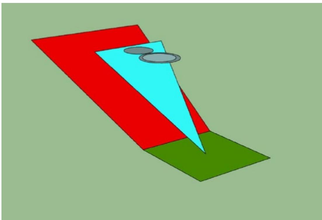
Figure II-3-11. Back-up area (showing representative types as D-size circles at their TDP – oblique view)
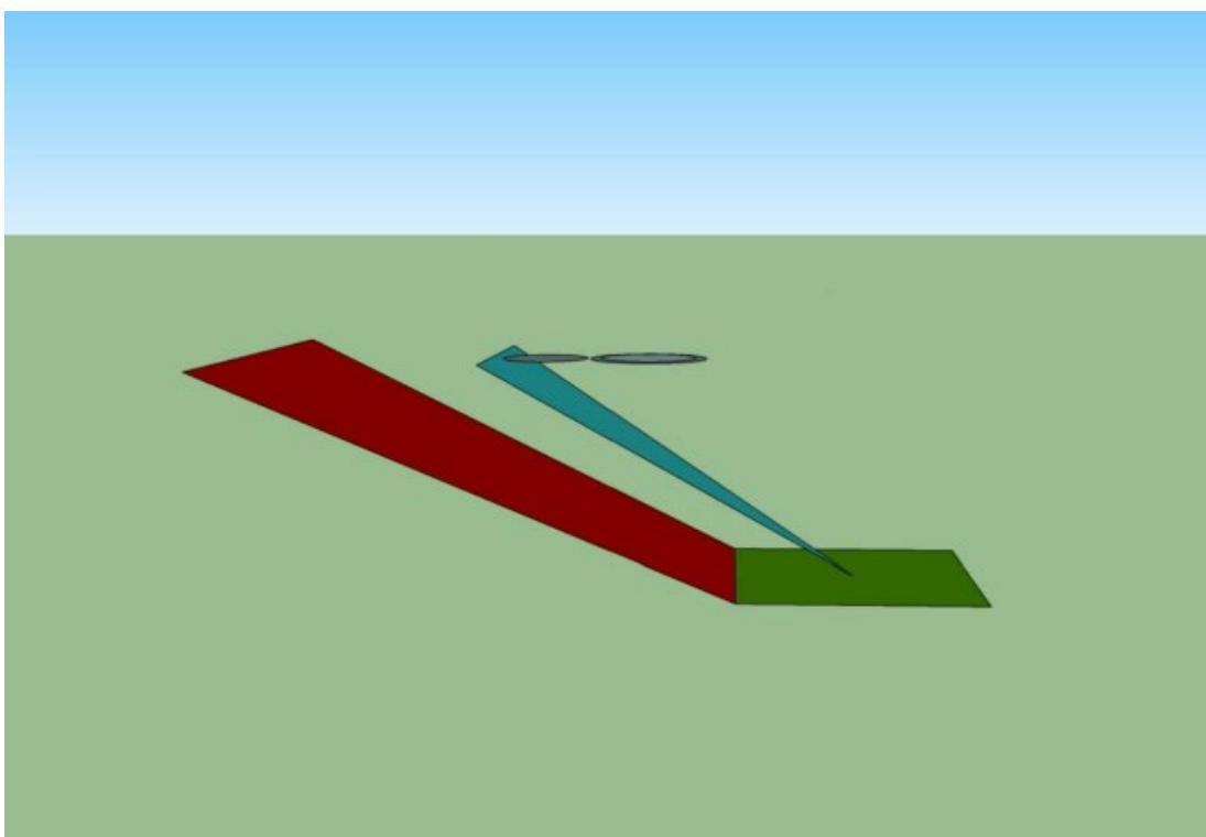
Figure II-3-12. Back-up area (showing representative types at their TDP- side view)
3.3 TLOF
3.3.1 General
3.3.1.1 Annex 14, Volume II, states that there will be at least one TLOF on a heliport. It further states that there will be a TLOF whenever a touchdown is intended at a FATO or on a stand. However, that does not preclude, for example, a manoeuvre where the helicopter air taxis from a FATO and then touches down on a taxiway16 to complete its movement to the stand.
3.3.1.2 Furthermore, Annex 14, Volume II, 3.1.29, states that every TLOF ‘shall be provided with markings which clearly indicate the touchdown position and, by their form any limitations on manoeuvring’. The intent of this statement is to make clear that, regardless of which type of touchdown is performed, the integrity of the defined area and the safety of the helicopter depends on the touchdown being accurately conducted on the TD/PM.
3.3.1.3 There are four basic types of TLOF: in each case, the arrival and touchdown can be viewed from different perspectives:
a) TLOF within a PC2/3 FATO: a touchdown following an approach;
b) TLOF within a stand: a touchdown following a taxi manoeuvre;
c) TLOF within a PC1 helipad FATO: a touchdown (from an approach or rejected take-off) that can be completed with OEI touchdown (without a run-on landing); and
d) TLOF within an elongated PC1 FATO with or without a declared RTOD: a touchdown (from an approach or rejected take-off) that can be completed with OEI touchdown (which may, or may not, include a runon landing).
3.3.1.4 From the basic types of TLOF shown above, the touchdown could be from:
a) hover taxi;
b) PC1 rejected take-off or OEI approach – with or without forward speed;
c) approach to the hover (the usual case); or
d) PC2/3 approach when exposed.
3.3.1.5 In addition, the direction of arrival at the TLOF or subsequent manoeuvring may be subject to limitations; this could affect the heliport design process with respect to containment.
3.3.1.6 Annex 14, Volume II, is primarily concerned with the minimum dimension of a TLOF with respect to the design helicopter; the apparent result of this is a TLOF that is fixed in size and in a defined position with respect to the FATO or stand. However, that may not always be the case; some basic examples include:
a) minimum sized TLOF in a minimum sized FATO;
b) oversized TLOF that is coincidental with a minimum sized FATO;
c) oversized TLOF in an oversized FATO;
d) TLOF in an elongated FATO; and
e) coincidental TLOF, PC1 FATO and compliant RTOD.
3.3.1.7 The TLOF should always be centred on the FATO or stand and, for an elongated FATO, centred on the longitudinal access.
3.3.1.8 If the TLOF and FATO are larger than the minimum dimensions, the designer has the possibility of offsetting the TDPC (not the TLOF). However, the centre of the TDPC in the offset position should be no closer to the boundary of the TLOF than 0.42 Design D and no closer to the boundary of the FATO than 0.75 Design D (as shown in Figure II-3-13) (regardless of the size of the TLOF or FATO, a TDPC should always have an inner diameter 0.5 Design D).
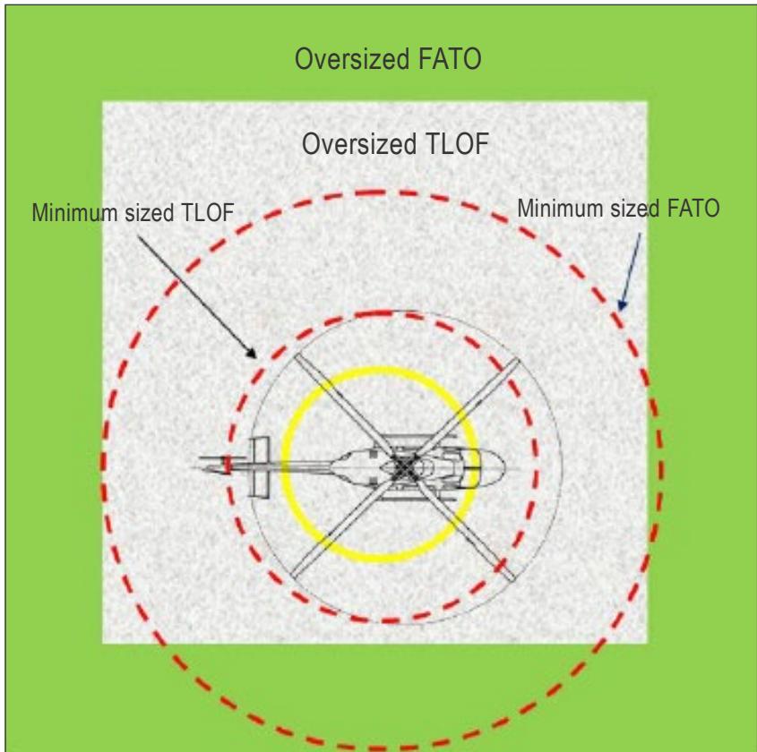
Figure II-3-13. Offsetting the TDPC in an oversized TLOF and FATO
3.3.1.9 The offset TDPC is more appropriate for a PC2/3 than a PC1 TLOF as the limitations on placement are associated with the physical dimensions of the helicopter and not the required performance.
3.3.1.10 Additional TDPCs may be contained in a PC1 TLOF and may be offset if these meet the conditions stipulated in 3.3.1.8 (Figure II-3-13). However, there should be measures in place to ensure that only one TDPC in the TLOF is used at any one time in PC1 operations.
3.3.2 TLOF attributes: containment
Containment of the undercarriage is assured by the provision of an adequately sized TLOF.
3.3.2.1 The TLOF within a PC2/3 FATO or stand
3.3.2.1.1 The size of the TLOF within a PC2/3 FATO or stand is directly related to the physical dimensions of the helicopter (for the FATO this should be the design helicopter, and for the stand the most demanding helicopter it is intended to serve), under all expected or anticipated conditions of arrival (approach or hover taxi) and positioning. The set of undercarriages of all single main-rotor helicopters of the same D can be contained, for omnidirectional positioning, within a circle of 0.83D: centred on the helicopter mid-point.
3.3.2.1.2 Where a restriction is placed on the direction of touchdown, e.g. the undercarriage may only be placed fore and aft direction, the width of the TLOF may be reduced to twice the undercarriage width. The use of undercarriage width in this case is possible because the configuration of the undercarriage with respect to the longitudinal axis has little bearing upon its lateral position. If this reduction in width is also associated with a reduced width of the FATO or stand, there will also be a restriction on manoeuvring.
3.3.2.1.3 For an elevated heliport with a collocated portion of the FATO in space, the safety of essential operations around the helicopter is considered. These operations include the offloading of passengers (sometime on a stretcher) or freight and movement around the helicopter for refuelling, maintenance or inspection, etc. In view of this, the minimum TLOF size, specified in Annex 14, Volume II, is 1 Design D unless collocated with a stand, or FATO with a solid surface of at least 1 x Design D.
3.3.2.2 The TLOF within a PC1 helipad FATO
3.3.2.2.1 The size of the TLOF within a PC1 helipad FATO is not directly related to the physical dimensions of the helicopter(s) but to the amount of surface that is required for a reject or OEI landing.
3.3.2.2.2 As discussed in Appendix C to Chapter 3, the minimum dimension will be the larger of three elements:
a) minimum size of the surface to contain the undercarriage;
b) aircraft performance scatter during the OEI landings to a specific reference point; and
c) surface required to provide the minimum suitable visual cues for a safe OEI landing.
3.3.2.2.3 The minimum dimension will be provided in the RFM (probably) as ‘the minimum elevated heliport size demonstrated’.
Note.— This is the term that is taken from certification guidance. However, manufacturers also apply this to surface-level heliports and use other terms approximating to that meaning.
3.3.2.2.4 When assessing the required TLOF size, a survey of the RFM helipad dimensions of all helicopters within the limits of the design helicopter should be considered. Targeting the dimensions on a more powerful type could limit the scope of PC1 operations at the heliport.
3.3.2.2.5 As in 3.3.2.1.3, a PC1 elevated heliport with a collocated portion of the FATO in space should have a TLOF of at least 1 x Design D.
3.3.2.3 TLOF within an elongated PC1 FATO with or without a declared RTOD
3.3.2.3.1 As with the helipad procedure, the size of the TLOF is that required for a reject or OEI landing (see Figures II-3-3 and II-3-4).
3.3.2.3.2 The minimum dimensions provided in the RFM are likely to be:
a) for the runway-type (clear area) procedure, a weight/altitude/temperature (WAT) graph containing the RTOD; and
b) for a short field/confined area procedure, a single dimension with some representative name.
3.3.2.3.3 If there is a declared RTOD in compliance with the certification guidance, containment of the whole helicopter will be included and the FATO and TLOF will be coincidental.
3.3.2.3.4 If there is a declared RTOD without full containment or a representative dimension, it is likely to represent only the required size of the TLOF.
3.3.2.3.5 When establishing the size of the TLOF, the PC1 dimensions for all helicopter types within the limits of the design helicopter should be considered.
3.3.3 The TLOF attributes — surface conditions
3.3.3.1 Surface loading
3.3.3.1.1 As specified in Annex 14, Volume II, the surface of the TLOF should have ‘…sufficient bearing strength to accommodate the dynamic loads associated with the anticipated type of arrival of the helicopter at the designated TLOF’.
3.3.3.1.2 The term ‘type of arrival’ is intended to provide a context that includes an engine failure, within which the required dynamic loading can be framed. There are three types of arrival:
a) arrival at the TLOF in a stand from a taxi manoeuvre17, or the arrival from a PC1 rejected take-off or OEI landing;
b) arrival from a PC2/3 approach or departure when not exposed to a surface or heliport platform; and
c) arrival from a PC2/3 approach or departure when exposed to a surface or heliport platform.
3.3.3.1.3 These three types of arrival may be categorized respectively as:
a) certification limit load (for normal touchdown), which is tested with an impact velocity of 1.98 m/sec;
b) certification ultimate load (for a hard touchdown), which is tested with an impact velocity of 2.4 m/sec; or
c) ultimate limit state (for the emergency touchdown), which relates to an impact velocity of 3.6 m/sec.
3.3.3.1.4 The dynamic loading of the surface should be in accordance with the type of arrival and touchdown. A more comprehensive discussion on the issue of surface loading can be found in Appendix B to Chapter 3.
3.3.3.2 The overall slope in any direction on a TLOF should not exceed 2 per cent except for elongated TLOFs. This enables sufficient drainage. The slope also enables helicopter landings when the mast moment indication is inoperative and slope landings with a slope of more than 5 per cent are prohibited.
3.3.4 TLOF associations
The TLOF is always associated with either a FATO or stand.
3.4 HELICOPTER TAXIWAYS AND TAXI-ROUTES
3.4.1 General
3.4.1.1 The SARPs for taxiways and taxi-routes were extensively modified and simplified in the 4th Edition of Annex 14, Volume II. Encapsulation allows the adjacent siting of taxiways/taxi-routes, but the practice is not recommended or encouraged.
3.4.1.2 Helicopters engaged in air taxiing produce rotor downwash; its effects can be felt far beyond the boundaries of the air taxi-route, especially with larger helicopters. The effect of rotor downwash can be extremely destructive to light aircraft and to small buildings. It is recommended that air taxi-routes are sited to avoid locations where this might occur and, where possible, ground taxiing for larger helicopters (with a mass in excess of 3,175 kg) is facilitated.
3.4.1.3 To provide flexibility to the designer, taxiways/taxi-routes may be provided for helicopters that are smaller than the design helicopter. If these are provided, the capacity of the taxiway/taxi-routes should have markings to indicate limiting dimensions. Allowing smaller18 skidded helicopters to air taxi on ground taxiways/taxi-routes could be permitted by the heliport operator if the helicopter width is less than or equal to 0.5 times the width of the ground taxi-route.
3.4.1.4 Guidance on air transit is included in 3.4.4. Although no longer addressed in Annex 14, Volume II, such guidance is commonly employed at airports and aerodromes, and could be employed at larger heliports. It is a very efficient method of repositioning helicopters on large airports, especially when helicopters are operating to and from the aeroplane runways.
3.4.2 Taxiways
3.4.2.1 General
A helicopter taxiway is intended to permit the surface movement of a wheeled helicopter under its own power. When a taxiway is intended for use by aeroplanes and helicopters, the provisions for taxiways included in Annex 14, Volume I, will be applicable, and the more stringent requirements should apply. A taxiway can be used by a wheeled helicopter for ground or air taxi when it is associated with the appropriately sized taxi-route.
3.4.2.2 Taxiway attributes
Containment for the undercarriage is provided by the 2 x undercarriage width (UCW) specified in Annex 14, Volume II. A State could permit a taxiway of less than 2 x UCW if the objective of containment can be met.
3.4.2.1.3 Surface conditions
3.4.2.1.3.1 Ground taxiing is a dynamic manoeuvre and surface loading should be at least that for a normal touchdown.
3.4.2.1.3.2 The transverse slope should not exceed 2 per cent and the longitudinal slope, 3 per cent. This will enable sufficient drainage. The slopes also enable helicopter landings within the limitations of the corresponding RFM.
3.4.2.1.4 Associations
The taxiway is associated with either a ground taxi-route or an air taxi-route.
3.4.3 Taxi-routes
3.4.3.1 Containment
A taxi-route should provide containment of the whole helicopter when ground or air taxiing. The containment area is predicated upon the maximum displacement from the centreline when in motion. This is likely to be greater for air taxiing than ground taxiing and is reflected in the minimum dimensions.
3.4.3.2 Surface conditions
3.4.3.2.1 When a surface is solid, it should be resistant to the effects of rotor downwash and free of hazards.
3.4.3.2.2 When collocated with a taxiway, the taxi-route should be centred on the taxiway. When solid, it should be contiguous and flush with the taxiway. Essential objects such as markers for the taxiway should be located on the taxi-route so as to not present a hazard to the helicopter.
3.4.3.3 Ground taxi-route
A ground taxi-route is intended to provide helicopter containment for a wheeled helicopter when ground taxiing (for a possible alleviation for air taxiing of smaller skidded helicopters, see 3.4.1.3).
3.4.3.4 Air taxi-route
3.4.3.4.1 A helicopter air taxi-route is intended to permit the movement of a helicopter above the surface at a height not above two rotor diameters and at ground speed less than 37 km/h (20 kts).
3.4.3.4.2 The probability of having to land on an air taxi-route does not justify a paved surface providing it is free of hazards that might prevent a safe forced landing and is resistant to the effects of rotor downwash.
3.4.3.4.3 The effect of downwash on other users and infrastructure should be considered when siting at an air taxi-route. Because of potential interference, adjacent siting of air taxi-routes is not recommended or encouraged.
3.4.3.4.4 The slopes of a solid surface of a helicopter air taxi-route should not exceed the slope landing limitations of the helicopter’s air taxi-route it is intended to serve. In any event, the transverse slope should not exceed 10 per cent and the longitudinal slope should not exceed 7 per cent.
3.4.4 Air transit routes
3.4.4.1 Ground and air taxiing by helicopters (primarily at an airport) are essentially slow manoeuvres and can prove to be economically and operationally embarrassing to helicopter and aeroplane operators alike. Therefore, when helicopters are required to move between widely spaced locations on an airport or aerodrome, it is desirable to allow air transit to permit the helicopter to fly more quickly while maintaining a safe manoeuvre capability.
3.4.4.2 Air transit should permit the movement of a helicopter above the surface, normally at a height not above
30 m (100 ft) above ground level and at ground speeds in excess of 37 km/h (20 kts).
3.4.4.3 Air transit, however, requires comparatively large amounts of airspace that is clear of obstacles, as well as corresponding areas of ground below suitable for safe emergency landings.
3.4.4.4 The width of an air transit route should not be less than that which would permit unhindered transit whilst allowing suitable space for errors in manoeuvring.
3.4.4.5 Variation in the direction of the centre line of an air transit route should be minimized such that the helicopter can be maintained in a level attitude when in flight.
3.4.4.6 Air transit routes should be selected to permit autorotative or OEI landings, minimizing injury to persons on the ground or water, or damage to property.
3.4.4.7 If it is planned to employ a virtual FATO as described in 3.2.3.4, the transit between the FATO and the stands could be by air transit.
3.5 APRONS AND STANDS
In Annex 14, Volume 1, covering aerodromes, apron and stands have an interdependent relationship that results in provisions relating to their physical characteristics being contained and associated with the Aerodrome Design Manual (Doc 9157), Part 2.
3.5.1 The apron
3.5.1.1 The SARPs in Annex 14, Volume I, covering aprons, provide few Standards, relying instead on objective statements contained in a series of recommendations. The methods for meeting these objectives are contained in Doc 9157 (design principles and examples).
3.5.1.2 Where an apron is envisaged for a heliport, Annex 14, Volume I, and the relevant part of Doc 9157 should be used as a basis for its provision.
3.5.2 The stand
3.5.2.1 General
3.5.2.1.1 The stand is a defined area primarily intended to accommodate a helicopter, its passengers and crew, heliport ground handling staff and equipment used for purposes of loading or unloading passengers, mail or cargo, fuelling, parking or maintenance. Where air taxiing operations are conducted, it will contain a TLOF. The stand may be designed for a helicopter of any size up to the D-value of the heliport.
3.5.2.1.2 As with all defined areas, encapsulation allows the stand to be positioned in isolation, or in combination with other defined or subsidiary areas. In the following sections, examples of stands are shown; this is not intended to limit the freedom of the designer in providing combinations of stands meeting the Standards of Annex 14, Volume II.
3.5.2.1.3 Only the ground area and surface conditions are specified in Annex 14, Volume II, and not the airspace under which it is situated. For a PC2/3 heliport, it is advisable not to position a stand or stands underneath a flight path in order to avoid, in case of an emergency landing of a helicopter on departure or arrival, the risk of collision involving parked helicopters.
3.5.2.1.4 As with the TLOF, Annex 14, Volume II, 3.1.29, requires the stand to ‘…be provided with markings which clearly indicate the touchdown position and, by their form any limitations on manoeuvring’. The integrity of the stand and the safety of the helicopter are dependent upon manoeuvring and touchdown being accurately conducted on the markings provided.
3.5.2.2 Manoeuvring on the ground (wheeled undercarriage)
For ground stands other than a taxi-through, manoeuvring with containment will depend on the radius curves and short lead-in/lead-out lines (between the curves). Each of these elements adds to the required dimensions of the stand (see Figure II-3-14). The radius curves should be within the limit of the radius of turn provided by the manufacturer19 (see also Appendix A to Chapter 3, 3.5.2). In the absence of substantiating data, the minimum radius of turn should be 0.5D.
3.5.2.3 Stand attributes — Containment
3.5.2.3.1 Containment is provided for the helicopter undercarriage and people and equipment necessary to carry out the functions performed on the stand. The minimum size for an air taxi or taxi-through stand is 1.2D (see Figure II-3-14); a ground taxi stand with entry/exit from a single side will require a greater area (see Figure II-3-15).
3.5.2.3.2 Containment of the helicopter is a function shared between the stand and its associated protection area as described in 3.5.2.5.
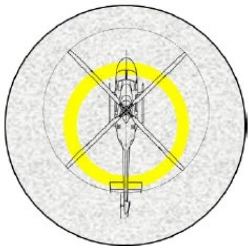
Figure II-3-14. 1.2D Stand with a helicopter on the TDPC
3.5.2.3.3 For a ground-taxi stand with an entry/exit from one side the minimum, dimension should be 1.2D plus, on the longitudinal axis, 2 x the recommended radius + the length of the lead-in/lead out line20 between the two radii (see Figure II-3-15). A stand along with its two entry/exit lead-in lines is considered to be one integral unit and should satisfy the requirements for (taxi-route) containment only on the outer boundaries.
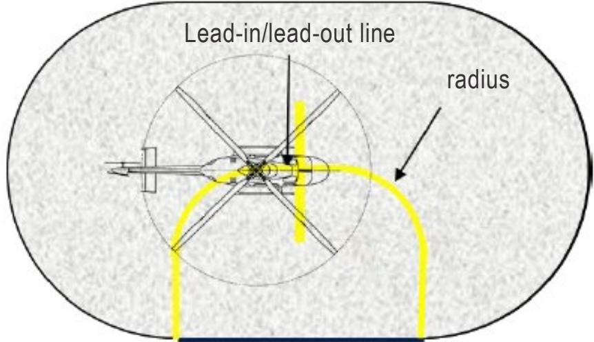
Figure II-3-15. Bi-directional ground-taxi stand with entry/exit from one side
3.5.2.3.4 If a ground-taxi stand is made dual purpose (for example when allowing smaller helicopter types to air taxi), a TLOF with a TDPC, centred on the stand, should be provided (see Figure II-3-16). The related taxiway should, in that case, be of an appropriate size (see the conditional text in 3.4.1.3).
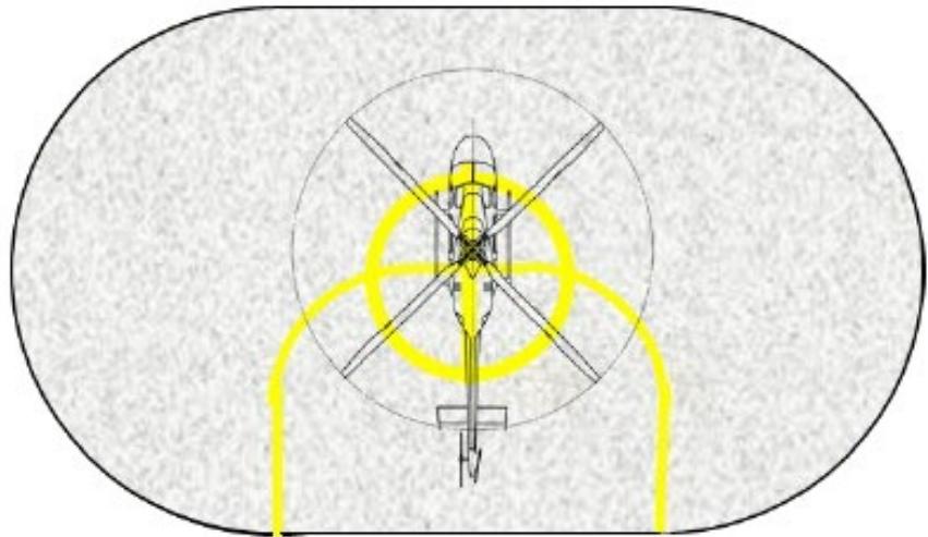
Figure II-316. Bi-directional ground taxi stand with integrated TLOF
3.5.2.4 Stand attributes — Surface conditions
3.5.2.4.1 The helicopter stand has similar surface condition requirements as the TLOF with the exception of surface loading. For that reason, surface loading only is considered here.
3.5.2.4.2 For a stand without a TLOF, access will be by ground taxiing. Since ground taxiing is a dynamic manoeuvre, it is recommended that the surface loading is at least that for a normal touchdown.
3.5.2.4.3 For a stand with a TLOF, the area outside the TLOF does not need dynamic loading but, for safety reasons, it is recommended that it is the same as the TLOF.
3.5.2.4.4 For a stand that is used by vehicles and equipment in the servicing of aircraft, the surface should be capable of withstanding the traffic that is intended. Ground service vehicles and equipment might place a greater load on the stand (and TLOF) than a helicopter and this should be reflected in the surface loading (see also 3.1.8.3).
3.5.2.4.4 The mean slope in any direction on a stand should not exceed 2 per cent. This will enable sufficient drainage. The slope also enables helicopter landings when the mast moment indication is inoperative and slope landings with a slope of more than 5 per cent are prohibited. Wheeled helicopters can be manoeuvred without effects on the airframe of the helicopter.
3.5.2.5 Stand associations and subsidiary areas - Protection area
The protection area serves a function similar to a combined FATO/SA; it extends outwards from the periphery of the stand and does not require a solid surface.
3.5.2.5.1 Containment
3.5.2.5.1.1 Helicopter containment provides for positioning within the stand and errors of manoeuvring. The size of the containment area is dependent upon the type of approach to the stand and limitations on manoeuvring.
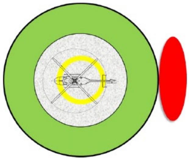
Figure II-3-17. Single stand with protection area – object on perimeter of stand
3.5.2.5.1.2 Turning stand. Where there are no limitations on manoeuvring, the protection area extends 0.4D from the periphery of the stand, regardless of whether it is approached from the hover or by ground-taxi.
3.5.2.5.1.3 Taxi-through stand. It has a protection area directly related to the size of the equivalent taxi-route. The protection area should be centred on the stand and have a minimum dimension of, for ground taxi, a ground taxi-route (1.5 x overall width of the largest helicopter it is intended to serve); or, for air taxi, an air taxi-route (2 x overall width).
3.5.2.5.1.4 Collocated stands. As with all defined areas, encapsulation allows stands to be located in isolation or in combination.
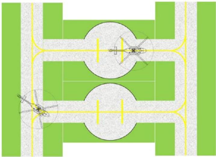
Figure II-3-18. Ground taxi-through stands (with taxiway/ground taxi-route)
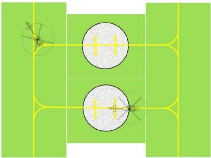
Figure II-3-19. Air taxi-through stands (with air taxi-route)
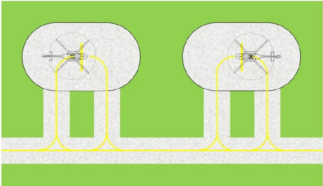
Figure II-3-20. Ground taxi stand with entry/exit from a single side
3.5.2.5.1.5 The protection area of stands may overlap when non-simultaneous operations are authorized (Figure II-3-21 shows a normal configuration and Figure II-3-22 shared protection areas). This relaxation is based upon the principle that encapsulation allows static objects to be contained on the boundary of any defined and associated subsidiary area (as per Figure II-3-17). An object in the adjacent stand should be contained entirely within the stand boundary and should be inactive. There should be positive control of taxiing in adjacent stands.
All Stands Active
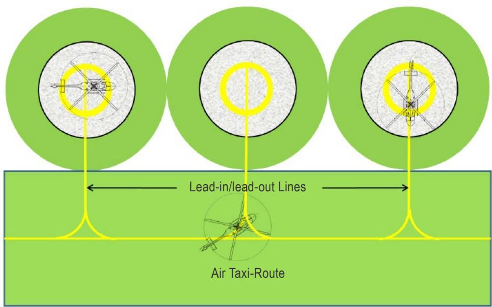
Figure II-3-21. Turning stands with air taxi-routes: simultaneous use with all stands active
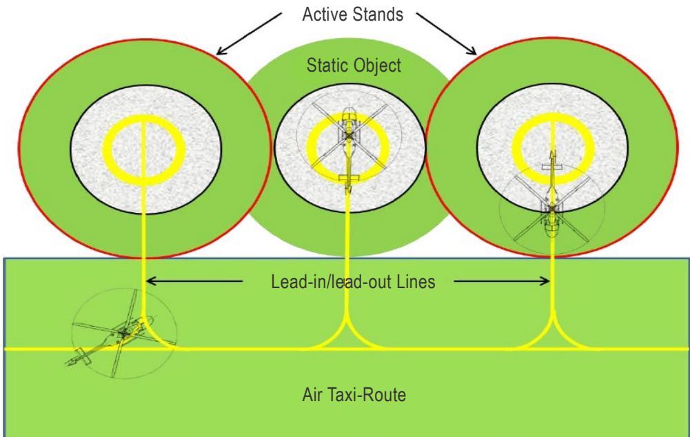
Figure II-3-22. Turning stands with air taxi-routes: non-simultaneous use with outer stands active
3.5.2.5.2 Surface conditions
3.5.2.5.2.1 The protection area is not required to be solid and has attributes similar to those for a collocated FATO and safety area. Essential objects such as visual aids and firefighting systems may be contained in the protection area:
a) for that part of the protection area up to 0.75D from the centre of the stand (the equivalent of the FATO), penetrating a plane 5 cm above the surface of the stand; and
b) at or from 0.75D from the centre of the stand (the equivalent of the SA), penetrating a plane 25 cm above the stand sloping upwards and outwards at a gradient of 5 per cent.
3.5.2.5.2.2 The Standard allows essential objects up to 25 cm between all collocated stands, including those with a shared protection area, except for ground taxi-through stands with a protection area based upon ground taxi-routes, where they would be restricted to 5 cm.
3.5.2.5.3 When solid, the surface should not exceed an upward slope of 4 per cent outwards from the edge of the stand. The slope on a protection area is consistent with that of the safety area. Where several stands are combined and interconnected, the slope on the protection areas should not exceed the mean slope of the stands.
Appendix A to Chapter 3
THE DESIGN HELICOPTER1
1. GENERAL
1.1 The introduction of the design helicopter in Annex 14, Volume II, removed the link between the design process and a specific type of helicopter.
1.2 This permits a simplification of the process - aggregating the most demanding set of helicopter dimensions into the design helicopter, which could then be used to set limits for defined areas.
1.3 In order to define the critical design helicopter, the following elements have to be established:
a) MTOM;
b) largest dimension of the helicopter with the rotors turning (D);
c) largest width of the helicopter (which is generally accepted to be RD);
d) largest UCW;
e) largest containment area for all undercarriages (length and width (TLOF));
f) largest distance between the Main Rotor Centroid and the mid-point of the D;
g) required dimensions for hover and, if applicable, ground turning;
h) wheel/skid loading (to establish the surface loading requirements);
i) fuselage length/width (for the RFFS calculations); and
j) critical obstacle avoidance criteria for obstacle limitation surfaces.
1.4 Items a) and b) are not discussed here as they are the basic designators2; h) is discussed in Appendix B; and i) in Chapter 6. The remaining items will be examined in detail to see how they impact on each other and heliport design.
Note.— To assist with this examination, data for analysis is taken from the (corrected) tables that are contained in Appendix B of AC 150/5390-2C issued by the Federal Aviation Administration (FAA) on 24 April 2012.
2. METHODOLOGY
2.1 In the following sections, where possible3, each of the critical design elements is statistically analysed to establish how any existing figure/ratio stands up to examination. Where a figure/ratio has not been provided, there is a suggestion on what a representative figure for a critical element might reasonably be.
2.2 An FAA data set has been partitioned into subsets of Design D; any boundary chosen can be regarded artificial but there do appear to be natural boundaries at D values of 22 m (72 ft), 15 m (50 ft) and 12 m (40 ft). Where necessary, these boundaries have been used in the following analyses4.
2.3 Establishing the Design D will be one of the first choices of the designer; once decided, appropriate analysis of the data set can be undertaken.
3. CRITICAL DESIGN ELEMENTS
3.1 Rotor diameter (RD) or largest overall width
3.1.1 The rotor diameter (for single-main rotor helicopters5) represents the widest dimension of a helicopter when the rotors are turning; it is used to establish the width of areas where the helicopter is intended to travel bi-directionally, i.e. taxi-routes, taxi-through stands or the obstacle limitation surfaces.
3.1.2 The figure of 0.83D, i.e. a proportion of the Design D, has been used as the standard for largest over width (RD) of the design helicopter. The abbreviation RD was deleted from Annex 14, Volume II (although the term ‘rotor diameters’ is still used to define the outer width of the obstacle limitation surfaces); however, it is used in this appendix.
3.1.3 If data for all single rotor helicopters in FAA AC 150/5390-2C is examined, the result in Table II-3-A-1 is observed:
Table II-3-A-1. Rotor Diameter
| Full Data Set (53 values) | |
| Mean | 0.85D |
| Minimum | 0.75D |
| Maximum | 0.90D |
| Values >0.83D | 45 |
| Values <=0.83D | 8 |
Note.— For this analysis, the full data set was used as there was no statistically significant difference between the superset and three subsets.
3.1.4 It is clear from the analysis that the proportion of the D that represents the rotor diameter should not be 0.83D as only eight of the 53 helicopters examined fall within that value; for that reason, in Annex 14, Volume II, ‘overall width’ is used in its full form.
Note.— It should be stressed, that the value chosen for the required area for undercarriage containment (TLOF) is not derived from the rotor diameter; it is just a co-incidence that the two values are the same.
3.2 Undercarriage width
3.2.1 The UCW represents the widest dimension of the undercarriage; it is used to establish the width of areas on which the helicopter is intended to travel, or be placed, bi-directionally, i.e. the taxiway or a TLOF with limited manoeuvring.
3.2.2 When introducing the design helicopter, it was considered that as many values as possible should be expressed as proportions of ‘D’. In order to establish whether this could be achieved for undercarriage widths, an analysis was carried out using the data in FAA AC 150/5390-2C with the results shown below.
3.2.3 Table II-3-A-2 shows an aggregation of the data to establish the mean/min/max values of UCW, and the proportion of that width to RD and D in multiples of 1.5 and 2 UCWs. The first section of the table uses the complete data set; subsequent rows have the results partitioned into subsets with the design helicopter D respectively set at 72 ft (22 m), 50 ft (15 m) and 40 ft (12 m) 6.
Table II-3-A-2. Undercarriage widths
| Complete dataset from AC 150/5390-2C (including S64) | |||||||
| UCW | 1.5UCW | 1.5 UCW/RD | 1.5 UCW/D | 2UCW | 2UCW/RD | 2UCW/D | |
| Mean | 8.32 | 12.48 | 0.32RD | 0.27D | 16.64 | 0.43RD | 0.36D |
| Min | 5.50 | 8.25 | 0.22RD | 0.19D | 11.00 | 0.30RD | 0.26D |
| Max | 19.90 | 29.85 | 0.48RD | 0.36D | 39.80 | 0.64.RD | 0.48D |
| Design data (largest value and proportion of a Design D of 72 ft (22 m)) | |||||||
| 14.00 | 21.00 | 0.35RD | 0.29D | 28.00 | 0.47RD | 0.39D | |
| Design data (largest value and proportion of Design D of 50 ft (15 m)) | |||||||
| 8.80 | 13.20 | 0.32RD | 0.27D | 17.60 | 0.43RD | 0.36D | |
| Design data (largest value and proportion of Design D of 40 ft (12 m)) | |||||||
| 8.80 | 13.20 | 0.40RD | 0.34D | 17.60 | 0.54RD | 0.45D | |
3.2.4 The conclusion reached is that the UCW proportion in terms of RD and D do not follow a set pattern7; there is therefore no benefit in specifying the ratio of undercarriage width to proportions of either D or RD.
3.3 Required containment area for the undercarriage
3.3.1 Because of the containment area for the undercarriages of helicopters, ‘a heliport is intended to serve’ cannot be derived from a single type or common types; it is necessary to establish a sound method for producing a minimum dimension which can be regarded as safe. As shown below, this cannot just be a proportion of a specific helicopter type’s undercarriage length or width because the configurations of undercarriage vary so widely. Where a tail-dragger’s undercarriage might be displaced mainly behind the mid-point, that for the nose-wheel might be predominantly forward of that point. Both of these types, as well as skidded undercarriages, have to be considered in order to establish a safe minimum containment area as the first step8 towards defining a minimum size for the TLOF.
3.3.2 In previous years, the minimum area required for touchdown was established as1.5 times the length or the width of the undercarriage, whichever is the greater, of the largest helicopter the area is intended to serve.
3.3.3 This method is no longer appropriate; unlike the undercarriage width, which has a symmetrical distribution either side of the rotor centroid, the longitudinal distribution may have a forward or rearward bias. The effect of this can be seen from the S76 in Figure II-3-A-1(a representative modern medium twin), which has all wheels ahead of the helicopter mid-point.
Note.— Whilst the undercarriage could be contained within its own length, this would result in the theoretical minimum containment area (for the whole helicopter) in an omnidirectional FATO being 1.5D rather than 1D.
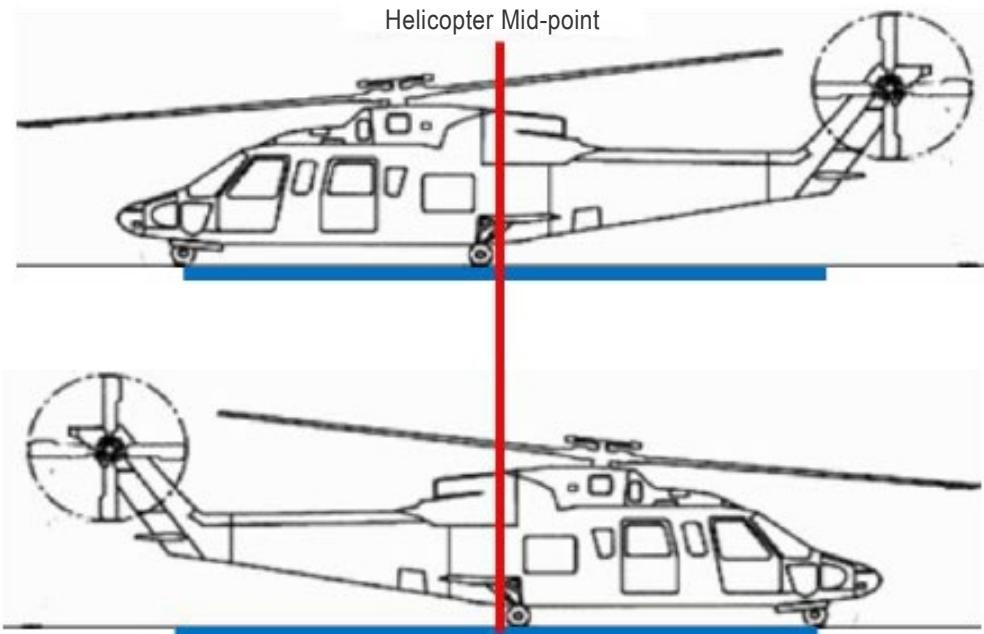
Figure II-3-A-1. S76 showing the absolute minimum undercarriage containment area
3.3.4 Under the previous Standard, the minimum size would have been 1.5 undercarriage lengths – i.e. 1.5 x 5 m = 7.75 m, when the minimum area to achieve undercarriage containment9 is 10.06 m (without contingency reserve) – i.e. more than twice the undercarriage length.
3.3.5 A similar situation exists for the AW139 in Figure II-3-A-2, where all wheels are also ahead of the helicopter mid-point and the minimum undercarriage containment area would also be more than twice the undercarriage length.
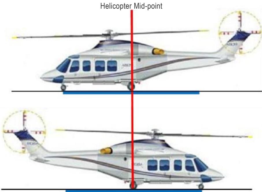
Figure II-3-A-2. AW139 showing the absolute minimum undercarriage containment area
3.3.6 Analysis was undertaken to establish the minimum area (expressed as a ratio of D) in which all undercarriages of a design helicopter could be contained, and it was concluded that with the pilot positioned above the 0.5D circle, a centrally located TLOF needs to be in the order of 0.83D of the design helicopter to contain all elements of the undercarriage of helicopters studied.
3.3.7 The data in the RFM normally shows the distance to the back of the skid, or to the front wheel, from the rotor centroid. However, as has been observed, the TLOF is not sited with respect to the rotor centroid but the mid-point of the helicopter; data manipulation has yielded the (selected)10 results for wheeled helicopters shown in Table II-3-A-3:
Table II-3-A-3. Static undercarriage containment (wheeled helicopters)
| Analysis of smallest required surface area for wheeled helicopters | ||||
| Type | UC FWD or AFTof mid-point | Length of UC (m) | Smallest surfacearea (m) | Smallest surface areaproportion of D |
| SA330 | FWD | 4.05 | 8.38 | 0.46 |
| AS332 /H215 | FWD | 5.27 | 8.35 | 0.45 |
| SA360 | AFT | 7.23 | 10.66 | 0.81 |
| AS365 | FWD | 3.64 | 7.37 | 0.54 |
| EC155 /H155 | FWD | 3.91 | 7.88 | 0.55 |
| LEONARDO 139 | FWD | 4.33 | 9.54 | 0.57 |
| EC225 /H225 | FWD | 5.25 | 10.09 | 0.52 |
| S61N | AFT | 7.16 | 8.13 | 0.37 |
| UH 60 | AFT | 8.84 | 11.76 | 0.60 |
| S76 | FWD | 5.00 | 10.06 | 0.63 |
3.3.8 As can be seen in Table II-3-A-3, where the ‘smallest surface area – proportion of D’ in the table exceeds
0.5D, the wheels will be outside the TD/PM – either FWD or AFT of the circle (in accordance with data shown in the table).
3.3.9 The smallest surface area (metres) depends upon the configuration of the undercarriage: where all parts of the undercarriage are either ahead or behind the mid-point of the helicopter, the smallest surface area will be more than double the length of the undercarriage11.
3.3.10 The smallest surface area shown is based upon absolute accuracy in aircraft geometry 12 and positioning without error. Clearly, neither of these assumptions can be relied upon in practice.
3.3.11 Less of a spread exists for skidded aircraft as can be seen from the (selected) results for skidded helicopters in Table II-3-A-4.
Table II-3-A-4. Static undercarriage containment (skidded helicopters)
| Analysis of smallest required surface area for skidded helicopters | ||||
| Type | UC FWD or AFT ofmid-point | Length of UC (m) | Smallest surfacearea (m) | Smallest surface areaproportion of D |
| B412 | FWD | 2.41 | 6.23 | 0.36 |
| SA341 | FWD | 1.95 | 4.01 | 0.33 |
| AS355 | FWD | 2.62 | 5.54 | 0.43 |
| EC135 /H135 | FWD | 3.20 | 6.61 | 0.54 |
| AS350 /H125 | FWD | 2.62 | 5.69 | 0.44 |
| BO105 | FWD | 2.53 | 5.73 | 0.48 |
| BK117 | FWD | 3.54 | 7.49 | 0.58 |
| EC120 | FWD | 2.87 | 5.43 | 0.47 |
| EC130/H130 | FWD | 3.20 | 6.57 | 0.52 |
| EC145 /H145 | FWD | 2.90 | 6.28 | 0.48 |
3.3.12 As indicated in Annex 14, Volume II, the provision of a minimum size TLOF relies upon analysis of the data and the addition of a safety factor. Unlike containment in width 13, containment in length is a much more complex issue; it has to consider skidded helicopters, wheeled helicopters with nose wheels (tricycle) and also tail wheels (tail draggers) within a population of helicopters for which the heliport has been designed.
3.3.13 Table II-3-A-5 shows the mean, minimum and maximum values for wheeled and skidded undercarriages. As expected, the maximum data value in the table is dominated by the result for the SA360; in view of this, the wheeled data reproduced in the second table excludes the SA360.
Table II-3-A-5. Mean undercarriage containment
| Smallest surface area as a proportion of D — wheeled (with outlier) | |
| Mean surface area | 0.54D |
| Minimum surface area | 0.37D |
| Maximum surface area | 0.81D |
| Smallest surface area as a proportion of D – wheeled (without outlier) | |
| Mean surface area | 0.51D |
| Minimum surface area | 0.37D |
| Maximum surface area | 0.63D |
| Smallest surface area as a proportion of D - skidded | |
| Mean surface area | 0.46D |
| Minimum surface area | 0.33D |
| Maximum surface area | 0.58D |
3.3.14 From this limited analysis, it is concluded that, leaving aside the predominant outlier (the AS360, which might have to be set aside and dealt with as a special case), positioning without taking errors into account requires at least a surface area of 0.63D for the population of helicopters.
3.3.15 Arriving at a safe and practical minimum size for the TLOF is not simple: adding a safety factor of 50 per cent would result in a minimum TLOF of:
For the mean of 0.51D of wheeled helicopters: 0.76D
Or the largest value of 0.63D of wheeled helicopters: 0.95D
3.3.16 However, in mitigation towards a figure of less than 0.95D, the errors in geometry of helicopters will rarely be more than 10 per cent; positioning errors, if the TD/PM is used, are likely to be less than 20 per cent. If both factors are applied to the maximum value, it would provide the following results:
Adding the 10 per cent geometry errors to the largest value in wheeled helicopters:
0.63D + 10 per cent = 0.693D
Adding the 20 per cent positioning errors 14 to this value would provide:
0.693D + 20 per cent = 0.83D
3.3.17 It is therefore concluded that, with the pilot positioned above the 0.5D circle, a TLOF needs to be 0.83D of the design helicopter to contain all elements of the undercarriage of helicopters studied.
3.3.18 However, there might be outliers like the AS 360, or the S-70, which require special treatment. It should also be understood that, because the contingency factor is smaller than normally provided in other annexes, deliberate misuse and non-compliance with positional marking conventions could result in a reduction in separation from obstacles to a hazardous level.
3.4 Distance between rotor-centroid and helicopter mid-point
3.4.1 In areas where turning is permitted, distance from obstacles depends on the turning circle of the helicopter i.e. the achievement of containment. The most natural method of performing an axial turn in a hover is to use the antitorque device to rotate the helicopter around the rotor-centroid. However, the rotor-centroid sits ahead of the helicopter mid-point by as much as 10 per cent of its length.
3.4.2 In the following analysis, an assumption is made that a helicopter will be situated in the centre of the defined area with the aid of a shoulder line or TD/PM (both of which provide a visual cue for the pilot that is set at 0.25D from the defined area centre point).
3.4.3 When the helicopter is accurately sited on its marking, the rotor-centroid sits one displacement value (green line above red line) ahead of the centre point of the defined area, as seen in Figure II-3-A-3.
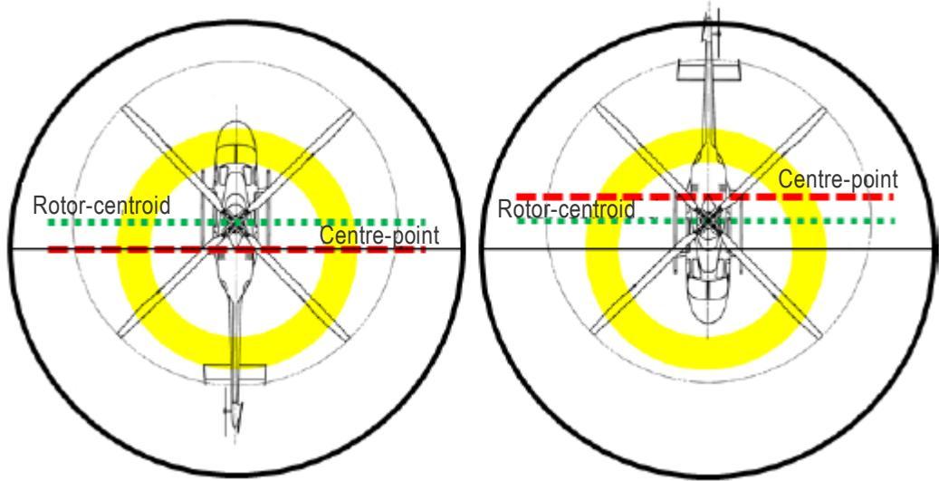
Figure II-3-A-3. Helicopter turning on rotor-centroid (black circle = 1.2D)
3.4.4 From any position on the TDPC, using the rotor centroid as a fulcrum, the rear of the helicopter will travel around a circle with a radius of 0.5D plus one displacement. The maximum travel will be 0.5D plus two displacements at the 180° turn point – after which the helicopter will start to return to the centre of its defined area.
3.4.5 Analysis of the data provides the information contained in Table II-3-A-6.
Table II-3-A-6. Rotor-centroid displacement
| Displacement of rotor-centroid from helicopter mid-point (53 values) | |
| Mean displacement | 0.08D |
| Minimum displacement | 0.05D |
| Maximum displacement | 0.13D |
3.4.6 The data indicates that, for any defined area in which turns are conducted around the rotor-centroid when the helicopter is correctly positioned on the TDPC, containment would have to be predicated upon the D of the helicopter plus four displacement values (two when commenced at one starting position and two when commenced at the diametrically opposed starting position) Hence, a containment area using the mean displacement value in Table II-3-A-6 would have to be 1.32D.
3.4.7 This minimum size is predicated upon three assumptions: (1) that the helicopter is placed in the centre of the defined area; (2) that all axial turns are performed around the rotor-centroid; and (3) that all defined areas have an unrestricted potential for manoeuvring.
Note.— There would be no benefit gained from attempting to place the helicopter with its rotor-centroid at the centre of the defined area. Any gain claimed would be based upon a false assumption that the helicopter could be accurately placed, and turned, without an external reference, by the ground or air crew.
3.5 Required dimensions for hover and ground turning
3.5.1 Turning in the hover
3.5.1.1 If a helicopter is precisely turned around its rotor centroid, its tail prescribes an circle with a diameter of
1.2D15 as shown in Figure II-3-A-4.
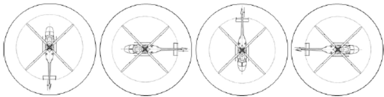
Figure II-3-A-4. Helicopter rotating around its rotor centroid
3.5.1.2 If a helicopter is precisely turned around its centre point, it will be contained within a circle of 1D, as shown in Figure II-3-A-5.
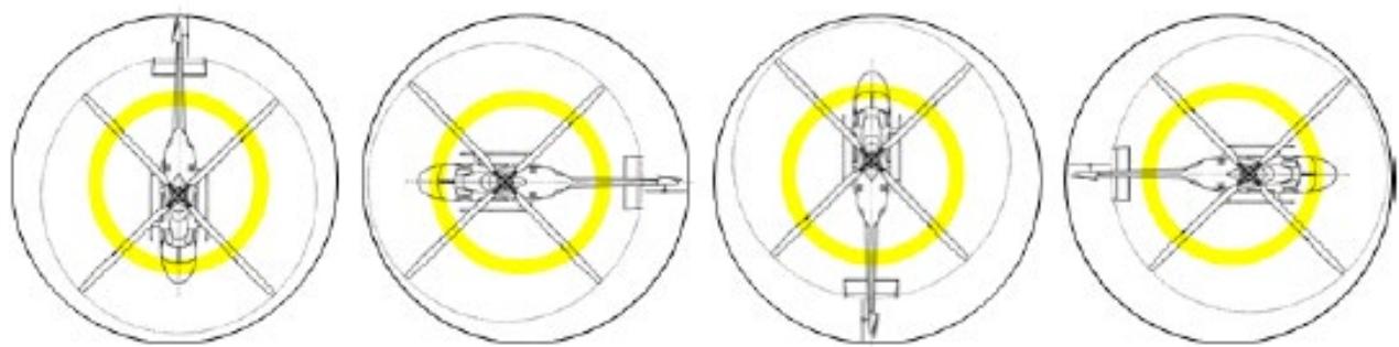
Figure II-3-A-5. Helicopter rotating around its centre point (showing the TDPC)
3.5.1.3 Aerodynamically, it is much easier to turn a helicopter around its rotor centroid because it makes best use of the anti-torque device. However, whilst this is the simplest and most efficient method of performing axial turns, it is not possible to maintain an accurate position in centre of the area.
3.5.1.4 Turning around the centre point of the helicopter is problematical because the pilot’s position would have to follow the TDPC, a combination of simultaneously turning and moving sideways which is difficult to do accurately given that the primary function of TDPC is to to provide accurate positioning cues for touchdown (i.e. the equivalent of the shoulder line) and not a reference for performing turns (manoeuvring).
3.5.1.5 In view of the potential errors in turning, helicopter containment for hover turning in the FATO is set to 1.5D.
3.5.2 Turning on the ground (wheeled undercarriage)
3.5.2.1 Theoretically, a wheeled helicopter can be turned around its rotor centroid; however, it can place an unacceptable strain on the undercarriage if the helicopter is forced to rotate in its own length. In addition, a short run along the longitudinal axis may be required for the releasing and setting of wheel locks.
3.5.2.2 If a helicopter is precisely manoeuvred around a radius-of-turn of 0.25D, it will be contained within a circle of
1.25D; and for a radius of turn of 0.5D, 1.75D, as shown in Figure II-3-A-6.
3.5.2.3 In practice, most wheeled helicopters will have a minimum radius of turn established by the manufacturer which should be used in the design process. In the absence of data, the minimum radius of turn should be 0.5D.
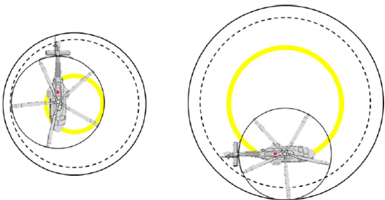
Figure II-3-A-6. Helicopter rotating around a circle of radius of 0.25 D and 0.5 D
3.6 Critical obstacle avoidance criteria for obstacle limitation surfaces
3.6.1 When establishing the obstacle limitation surfaces described in Chapter 4, the designer should take note of the Category A procedures of the population of helicopter types for which the heliport is intended, to ensure that they are fully accounted for in the definition of the design helicopter (see 3.2.4.4, Appendix A to Chapter 3 and Appendix D to Chapter 4). A realistic range of temperatures and density altitudes should be used when making this determination.
3.6.2 It should be noted that, in the case of heliports utilising vertical procedures, the Category A supplements of older types might contain conservative or very conservative slopes. In these cases, the designer might have to limit the types of helicopter for which the heliport is designed.
Appendix B to Chapter 3
SURFACE LOADING
1. GENERAL
Surface loading has a substantial effect on the requirements for heliport design. Two terms commonly used in the provision of surface loading are defined in common language:
a) static: having no motion; being at rest; quiescent1; and
b) dynamic: of, or relating to energy or to objects in motion.
1.1 Static loading
Static loading is not normally a critical design issue but might impact the safety of heliports if the distribution of undercarriage loading is not considered when establishing the attributes of the critical design helicopter2, which is then used to establish static loading.
1.2 Dynamic loading
1.2.1 With respect to the force that a helicopter exerts on a surface, a number of terms are used that are not universally defined, or have meanings that differ in reference documents. The three most commonly used terms with respect to a landing (touchdown) are normal, hard/heavy, and emergency:
a) normal landing. A normal landing may not interfere with safe operations; it is represented by the Airworthiness Standards for Rotorcraft (e.g. FAA Part 29 or EASA CS 29)3 limit load, and relates to a contact velocity of 1.98 m/sec4;
b) hard/heavy landing. A hard (or heavy) landing is not defined for helicopters; however, FAA Part 29 or EASA CS Part 29 stipulates that the ultimate load is one which the structure has to support without failure, i.e. the landing gear must withstand the ultimate load test without collapsing. In the FAA Part 29 or EASA CS Part 29 test, the vertical speed is set to 2.4 m/sec5. It is therefore reasonable to assume that a helicopter that has a contact velocity between 1.98 m/sec and 2.4 m/sec has been subject to a hard landing; and
c) emergency landing. It is extremely difficult to establish the conditions of an emergency landing beyond the undercarriage collapse load. Therefore, any classification system that wishes to apply design criteria to an emergency landing would have to have set its own arbitrary limit. In this manual, that limit is set to 3.6 m/sec6 and 2.5 g.
1.2.2 Converting contact velocity to heliport design criteria requires that the impact loads associated with those speeds be assessed. In FAA Part 29 or EASA CS Part 29, the undercarriage is subject to a drop test from a height that will provide, at impact, the vertical speeds stated for the ‘normal’ and ‘hard landing’ conditions, respectively 1.98 m/sec and 2.4 m/sec. Following the limit tests, the undercarriage (or element being tested) is inspected for distortion or damage; for the ultimate limit test, some distortion is permitted 7. The resulting force at the contact points will depend on the attenuation qualities of the undercarriage; the lower the attenuation, the higher the force.
1.2.3 The result of the drop tests has relevance to the serviceability of the aircraft following a normal or hard/heavy landing but, alone, does not provide design criteria for the heliport.
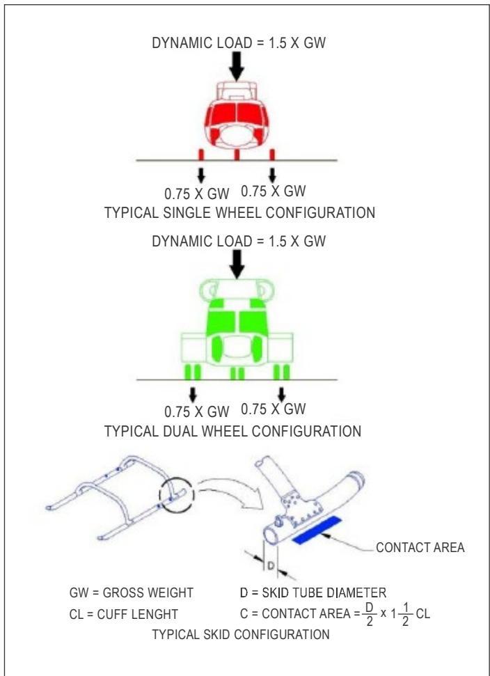
Figure II-3-B-1. Application of landing gear loading from FAA AC 150 5390-2C
1.2.4 The FAA employs a system provided in advisory circular AC 150 5390 which states8:
“A dynamic load of 0.2 second or less duration may occur during a hard landing. For design purposes, assume dynamic loads at 150 per cent of the take-off weight of the design helicopter. When specific loading data is not available, assume 75 per cent of the weight of the design helicopter to be applied equally through the contact area of the rear two rear wheels (or the pair rear wheels of a dual-wheel configuration) of a wheelequipped helicopter. For a skid-equipped helicopter assume 75 per cent of the weight of the design helicopter to be applied equally through the aft contact areas of the two skids of a skid-equipped helicopter. Contact manufacturers to obtain the aft contact area for specific helicopters of interest.” (See Figure 3.25).
1.2.5 As is stated in the International Organization for Standardization (ISO) 19901-3:
“Installations may be designed to accommodate a particular type of helicopter. Greater operational flexibility may result from a classification system of design.”
1.2.6 The classification system embodied in Annex 14, Volume II, is the design helicopter (see Appendix A). It is established after assessing the data (of the population of helicopters that the landing surface is intended for) provided by manufacturers with respect to the undercarriage drop tests and the wheel/skid loading forces.
1.2.7 With respect to the application of the design criteria, the following statements are taken from the Offshore Technology Conference (OTC) 2001/072, quoting ISO 19901-3:
“A helicopter heavy landing may occur infrequently as a result of an unfavourable combination of factors such as bad weather, minor mechanical problems and slight pilot mishandling. The consequent actions on the helideck structure will be within the envelope for the emergency landing condition.”
“The emergency landing condition is an accidental action condition expected to occur very infrequently and resulting from such serious events as loss of power, major pilot mishandling or fouling of landing gear during take-off and landing. Where the helicopter landing gear collapses, the body of the helicopter may then impact onto the deck, distributing the impact load further.”
1.2.8 The appropriate level of surface loading is that which matches the risk profile of the likely arrival. Whilst the emergency landing limit should be applicable to the TLOF of FATO, it should not be applicable to the TLOF in a stand.
2. PROVISION FOR SURFACE LOADING AND ITS ASSOCIATED TERMS
2.1 General
2.1.1 Annex 14, Volume II, relies on objective criteria leaving the precise methods of compliance to be described in guidance material in a State’s regulations. Terms used in the objective criteria include:
a) withstand the traffic of helicopters that the area is intended to serve;
b) have bearing strength sufficient to accommodate a rejected take-off by PC1 helicopters (i.e. helicopters operating in PC1);
c) be capable of supporting, without structural damage, the helicopters that the heliport is intended to serve;
d) routes selected permitting autorotative or OEI landings such that, as a minimum requirement, injury to persons on the ground or water, or damage to property are minimized; and
e) be suitable for emergency landings.
2.1.2 In seeking to understand the intent of these objective terms, it is necessary to look at their meaning in an operational or airworthiness context.
2.2 Withstand the traffic of helicopters that the area is intended to serve
2.2.1 This term is considered to imply two objectives:
a) the surface loading should be appropriate for the type of use intended; and
b) the likely intensity of traffic must be considered to ensure that the surface loading remains as specified for the life of the facility (or the applicable maintenance period) i.e. it must be durable.
2.2.2 This objective was applied to the TLOF and ground taxiway of a surface level heliport, and the FATO/TLOF of an elevated heliport. In effect, all contact surfaces would support dynamic loading and be durable with respect to the intensity of usage.
2.2.3 When used without the type of helicopter specified, for example, a defined area such as an apron or stand for which access is provided to vehicles and equipment other than the helicopter, consideration of the additional required surface loading might be necessary.
2.3 Have bearing strength to accommodate a rejected take-off
2.3.1 Category A procedures are demonstrated, during the certification process, to result in a safe landing in a rejected take-off. These procedures are also routinely practiced at representative masses during the pilot proficiency checks to ensure that they can be conducted without damage to the helicopter or injury to occupant.
2.3.2 In view of the fact that these landings can be conducted with the ROD of 1.8 m/s (6 ft/sec), it is considered that the RTOD needs to meet the normal landing provision.
2.4 Be capable of supporting, without structural damage, the helicopters that the heliport is intended to serve
2.4.1 This objective previously applied only to the safety area that abutted the FATO to provide an area in which the helicopter might land in the case of errors of positioning. Because the probability of such an occurrence was small, this area was permitted to contain frangible items such as lights and navigational aids.
2.4.2 Recently, this property was removed from the Safety Area because it was no longer required to be a solid surface.
2.5 Routes permitting autorotative or one-engine-inoperative landings
When used in an operational context, this was intended to describe a surface area where a safe forced landing could be achieved.
2.6 Be suitable for emergency landings
2.6.1 This objective was used for the air taxi-route: it could have meant one of two things:
a) the surface below the air taxi-route could support the ultimate design load of a helicopter which has had an engine failure; or
b) the surface below the air taxi-route was free of objects, other than those which are frangible and are permitted, such that any helicopter having an engine failure could land unimpeded.
2.6.2 Unlike the TLOF where the probability of a landing is 1, the probability of a landing in an air taxi-route is linked to failure of an engine. As indicated in Annex 6, Part III, the probability of an engine failure for modern engines is equal to or better than 1 x 10⁻⁵ (1:100 000) per flying hour.
2.6.3 As the duration of an air taxi is limited to the transit between FATO and stand and is unlikely to extend to more than two minutes, the probability of an emergency landing occurring on the air taxiway is no greater than 1:3 000 000 for a single and 2:3 000 000 for a twin engine.
2.6.4 The consequence of such a failure is putting the air taxiway out of commission for a short period. It is therefore unlikely that the authors intended that air taxi-route should be paved or provided with dynamic loading for an emergency landing. This would also have permitted a hover taxi from a FATO over water to a stand with a TLOF.
3. SUMMARY OF SURFACE LOADING
Note.— If applying a type of loading provided in this manual causes difficulties in States which have already constructed their regulations, the objective text the Annex 14, Volume II, should be observed and the choice of methods of compliance decided by the State.
3.1 Static loading
3.1.1 If static surface loading is required for a defined area, the basis for that loading, as per guidance referenced by this appendix, should be applied:
a) at the total contact surfaces of the wheeled undercarriage or skids; or
b) at the main wheels.
3.1.2 Static loading is not equally distributed between wheels, or over the whole surface area of skids; this should be considered when establishing the attributes of the design helicopter.
3.2 Dynamic loading
3.2.1 With respect to the provision of dynamic loading (using the FAA Part 29, EASA CS Part 29 and the previous edition of this manual as reference points), there appear to be three divisions:
a) Part 29 limit state (for normal touchdown): tested with an impact velocity of 1.98 m/sec;
b) Part 29 ultimate state (for a hard touchdown): tested with an impact velocity of 2.4 m/sec; or
c) ultimate limit state (for the emergency touchdown): relating to an impact velocity of 3.6 m/sec.
3.2.2 The force relating to a) and b) can be obtained from the test results performed during certification. The design helicopter should reflect the limits associated with the population of helicopters for which the heliport has been designed. The last is an arbitrary figure used since the advent of Annex 14, Volume II.
3.2.3 Limited conducted analysis indicates that the three basic values should be 1.5g, 2g, and 2.5g times the MTOM of the design helicopter (see also Chapter 3, 3.1.8).
3.2.4 As per Annex 14, Volume II, there are no assigned values to dynamic loading; that is left for a State to determine in accordance with its risk assessment. However, it is suggested that:
a) the Part 29 limit state (normal touchdown) be applicable to:
-
TLOF in a stand; and
-
ground taxiway;
b) the Part 29 ultimate state (hard touchdown) be applicable to:
- TLOF in a surface level FATO;
c) the Heliport Manual ultimate limit state (emergency landing) be applicable to:
- TLOF of an elevated heliport.
Appendix C to Chapter 3
ESTABLISHING THE REJECTED TAKE-OFF DISTANCE
1. DESCRIPTION OF THE ISSUE
1.1 There have been few changes to the helicopter certification standard in recent years. Although the last major revision of performance in the FAA Part 29 certification code (Amendment 29-39 - 1996) contained modification of the vertical profiles, the text still referred to the rejected take-off and landing distances and the necessity to include the entire helicopter, including the rotors, in the resulting dimensions.
1.2 For landing, and specifically for those Category A procedures with vertical components, additional guidance introducing a surface size was added, specifying that the minimum elevated heliport size demonstrated for the OEI approach procedure should also be provided in the Flight Manual.
1.3 For most procedures contained in the Category A Supplement of the Flight Manual, the minimum heliport size demonstrated might be the only dimension provided (thus serving both for take-off and landing) and, because there is no objective set in its provision, it has been used to reduce the minimum dimension for the Category A procedure to that of the ‘surface area requirement’ (undercarriage, not helicopter, containment). The consequence is that there may be no dimension in the RFM that provides for the safe containment of the entire helicopter during a rejected take-off or OEI landing.
2. ANNEX 14, VOLUME II AMENDMENT TO ADDRESS CERTIFICATION PRACTICES
2.1 Since a single dimension only may now be provided in RFMs, a revision was made in Annex 14, Volume II, objectives of the TLOF and FATO, to facilitate a solution and ensure continued safety:
a) TLOF was amended to contain only the surface area and loading for containment of the undercarriage (this now correlates with the dimension provided in the Category A Supplement); and
b) FATO was amended to strengthen the requirement for containment of the whole helicopter but the necessity for a solid surface area was removed.
2.2 The requirement of the (additional) FATO dimension is necessary to ensure protection of the helicopter from surrounding objects. This dimension can be derived (by the manufacturer) from ‘scatter plot’ data collected and recorded during the certification flight and acceptance trials.
2.3 In the absence of provision of the helicopter containment dimension, the addition of 1 x Design D to the dimension contained in the RFM Category A Supplement would ensure a safe FATO. In most cases, this would result in a slight addition to the minimum PC1 FATO dimension specified in Annex 14, Volume II.
3. RESOLUTION OF INCONSISTENCIES IN THE RFM (TLOF/FATO/RTODR)
3.1 The following is a description of the required dimension(s) (see Figure II-3-C-1 for a technical diagram):
3.1.1 The minimum demonstrated heliport size for the OEI approach procedure should be provided in the RFM. The minimum demonstrated heliport size represents the sum of:
a) size of the surface area (TLOF) required to contain the undercarriage of the rotorcraft;
b) aircraft performance scatter during OEI landings to a specific reference point; and
c) distance required to provide the minimum suitable visual cues for a safe OEI landing.
3.1.2 It should be noted that the minimum demonstrated heliport size does not necessarily guarantee rotor containment. The minimum rotorcraft containment area is defined as the larger of either:
a) minimum demonstrated heliport size; or
b) overall length of the helicopter (including main and tail rotor tip paths) plus the performance scatter seen in the heliport size determination.
3.1.3 If the minimum rotorcraft containment area is larger than the minimum demonstrated heliport size, the minimum rotorcraft containment area (FATO) should also be provided in the RFM1.
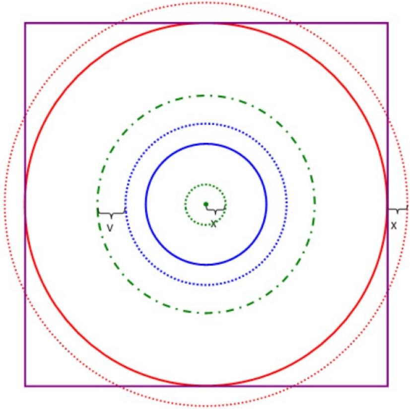
Figure II-3-C-1. Performance Class 1 TLOF/FATO (RTODR) dimensions
Physical dimensions
| Undercarriage containment area (UC)/width/length |
| Rotorcraft overall length (D) |
| Reference area of 1D |
| • Touchdown reference point |
| Performance/measured information |
| Touchdown performance scatter (aircraft reference point scatter – 2X) |
| +*++++++++ Undercarriage containment area plus two times the touchdown performance scatter |
| Minimum elevated heliport size demonstrated (AC 29-2C Para 29-75(b)(2)(vii) – includes UC +two times visual cues (2V) plus two times touchdown performance scatter (2X)) |
| Minimum rotorcraft containment area (MRCA) – overal length (D) plus the touchdownperformance scatter (2X) |
Appendix D to Chapter 3
ESTABLISHING A VIRTUAL CLEARWAY Note.— See also Appendix A to Chapter 4
1. DEFINITIONS
1.1 A virtual clearway is a helicopter clearway that extends outside the boundary of the heliport and complies with the helicopter clearway Standards and Recommended Practices (SARPs) provided in Annex 14, Volume II, Chapter 3, 3.1.16 to 3.1.20, inclusive.
1.2 The minimum dip is the lowest level in the continued take-off or balked landing.
2. GENERAL
2.1 The virtual clearway allows:
a) origin of the take-off climb surface to be extended beyond the boundary of a heliport so that a descent below the OLS in the TODRH can be avoided in the take-off phase of the profile;
b) use of a variable TDP to raise the elevation of the origin of the OLS above obstacles within a close proximity of the heliport (i.e. those that are directly beneath the projected clearway);
c) use of a variable TDP to raise the origin of the OLS above obstacles not in close proximity of the heliport (i.e. those beyond the projected clearway); or
d) use of the drop-down profile on an elevated heliport (where the obstacle environment permits it).
Note.— These elements apply also to clearance above obstacles in the balked landing.
2.2 Although not all current helicopter types have the appropriate Category A (variable TDP/LDP) procedures, sufficient numbers are now being deployed to make facilitation of the virtual clearway worthwhile. All types could take advantage of the ability to extend the origin of the OLS without the use of variable TDP/LDPs.
Where a State permits the use of the virtual clearway:
a) the heliport designer should ensure it is configured so as to permit use by the widest population of types and users;
b) operational procedures should be in place to ensure that, following an engine failure in the continued take-off or balked landing, the min dip is set so that the helicopter is able to clear all obstacles in the virtual clearway by a vertical margin of 10.7 m (35 ft); and
c) for the purposes of safeguarding, the virtual clearway should be regarded as one of the obstacle limitations surfaces (OLS).
3. DIMENSION OF A VIRTUAL CLEARWAY
3.1 The length of the virtual clearway should permit the achievement of the TODRH conditions, i.e. Vtoss and a positive rate of climb (+ROC), 10.7 m (35 ft) above the elevation of the virtual clearway, at or before the outer boundary.
3.2 The width of the virtual clearway should be the specified width/diameter of the FATO plus the safety area or, the reference circle (see Chapter 4, 4.1.1.8); or, when there is a lateral element, as shown in Appendix A to Chapter 4.
4. THE LOCATION OF A VIRTUAL CLEARWAY
4.1 The inner edge of a virtual clearway should be located at, directly above or directly below the outer edge of the safety area.
4.2 The inner edge of the take-off climb surface should be located at the outer edge of the virtual clearway.
4.3 A virtual clearway that is established at the elevation of the FATO may be used to extend the origin of the take-off climb surface to the outer edge of the virtual clearway (see Figure II-3-D-1).
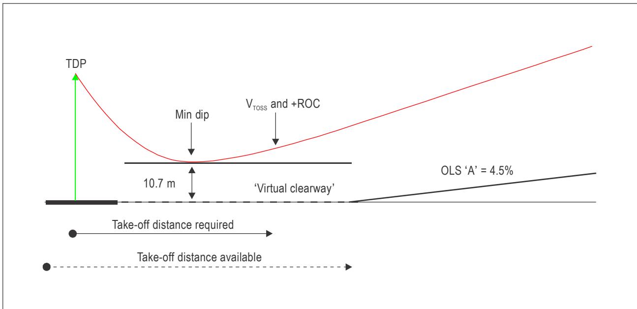
Figure II-3-D-1. Virtual clearway at elevation of the FATO
4.4 A virtual clearway that is established other than at the elevation of the FATO should be located at:
a) the level of the highest obstacle in the clearway (see Figures II-3-D-2, II-3-D-4 and II-3-D-5); or
b) an elevation to ensure that the OLS is above obstacles (see Figure II-3-D-3); the minimum dip should be no lower than 4.5 m (15 ft) above the clearway, providing the helicopter remains at least 35ft above any obstacle, or the surface, beneath the clearway
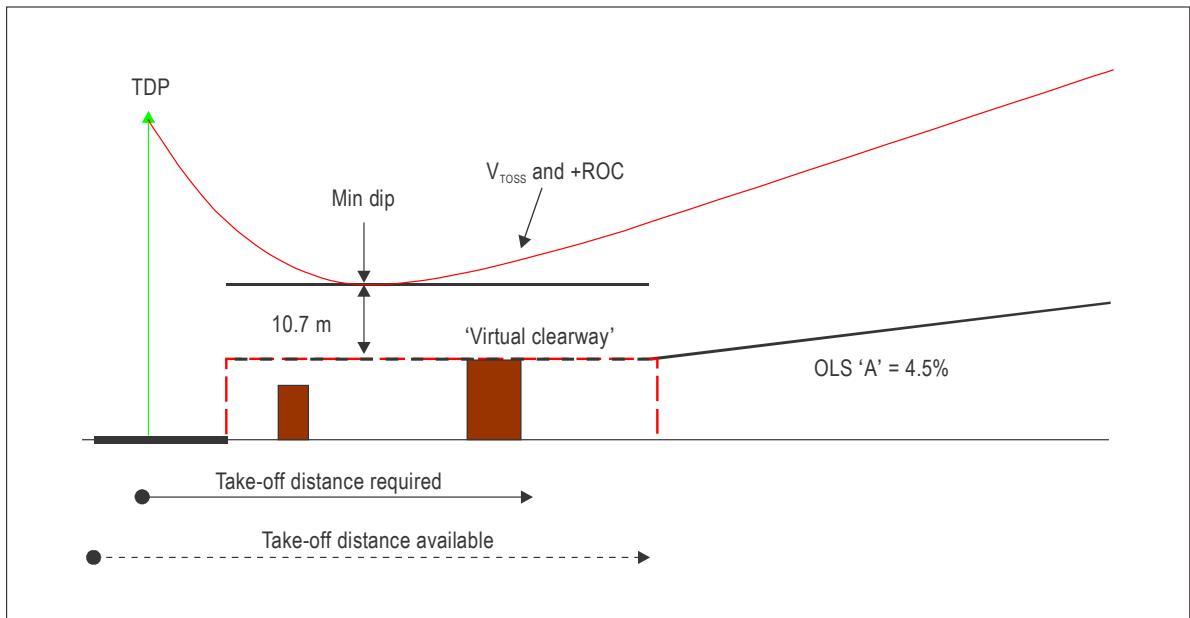
Figure II-3-D-2. Virtual clearway above the level of the FATO (obstacles in clearway)
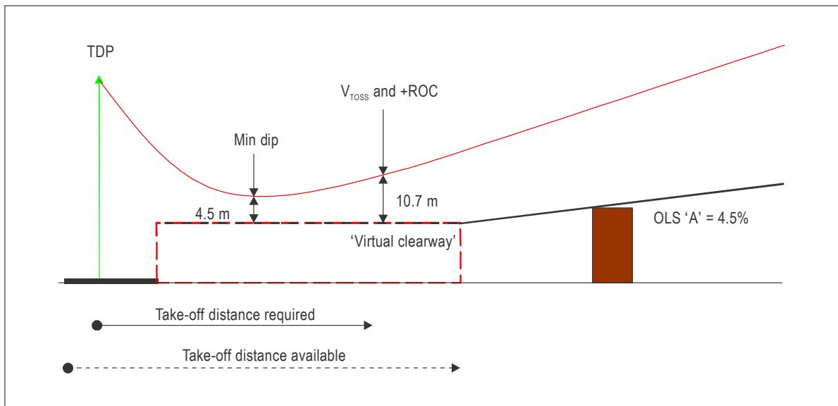
Figure II-3-D-3. Virtual clearway above the level of the elevated FATO (obstacle in OLS)
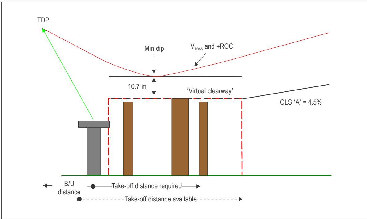
Figure II-3-D-4. Virtual clearway above the level of the elevated FATO
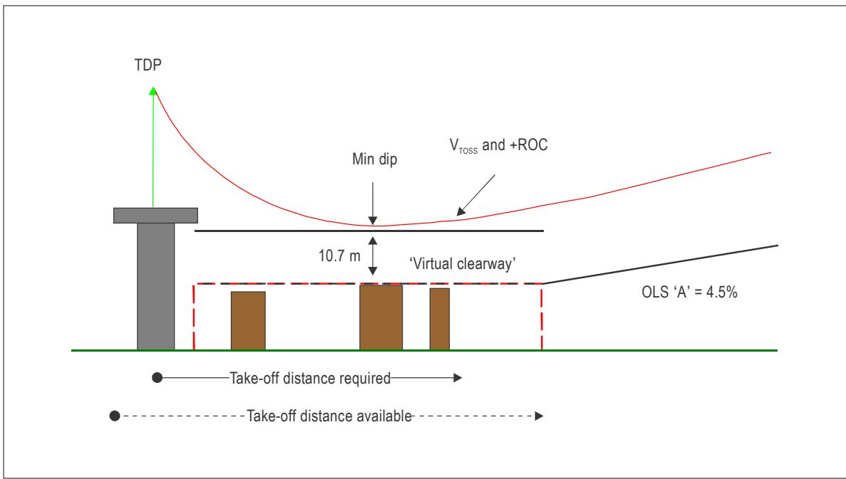
Figure II-3-D-5. Virtual clearway below the level of the FATO
4.5 When the PC1 procedure includes a lateral element, the virtual clearway should be as shown in Appendix A to Chapter 4.
OBSTACLE ENVIRONMENT
4.1 OBSTACLE LIMITATION SURFACES AND SECTORS
4.1.1 General
4.1.1.1 The specifications in Annex 14, Volume II, Chapter 4, define the airspace around heliports to be maintained free from obstacles so as to permit the intended helicopter operations at the heliports to be conducted safely and to prevent the heliports becoming unusable by the growth of obstacles around them. This is achieved by establishing a series of obstacle limitation surfaces that define the limits to which objects may project into the airspace.
4.1.1.2 In order to safeguard a helicopter during its approach to the FATO and in its climb after take-off, an approach surface and a take-off climb surface through which no obstacle is permitted to project is established for each approach and take-off climb path designated as serving the FATO.
4.1.1.3 The minimum dimensions required for such surfaces will vary considerably and depend on:
a) helicopter size, its climb gradient, particularly for multi-engine helicopters with OEI, its approach speed and rate of descent on the final approach, and its controllability at such speeds; and
b) conditions under which the approaches/departures are made, for example, whether from a VFR approach/departures or from a PinS approach/departure procedure with proceed visually instruction.
4.1.1.4 Once such surfaces are established, it may become necessary to remove existing obstacles which project through the surface and restrict the erection of new structures which would become obstacles (safeguarding is addressed in Chapter 2). Mobile or temporary objects such as cranes, lorries, boats and trains may be obstacles at times, in which case it might be necessary to delay helicopter operations until the obstacle is moved clear, or temporary operational limits are temporarily established (e.g. reduction of take-of mass). For longer lasting temporary obstacles, supplementary take-off climb or approach surfaces might have to be developed and promulgated.
4.1.1.5 In many instances, the presence of permanent, high obstacles such as radio masts, buildings or areas of high ground may preclude the provision of the required take-off climb/approach surfaces for a straight take-off climb or approach, whereas the criteria required for the surfaces would be feasible if:
a) a curved flight path avoiding the obstacles is established (see 4.1.1.7); or
b) the origin of the approach or take-off climb surfaces is elevated (see Appendix A to Chapter 4) with or without a turn.
4.1.1.6 For heliports used for operations in PC2 and PC3, approach and take-off climb paths may be selected to permit the safe forced landings or OEI landings that minimize personal injury on the ground or water, or property damage. The design helicopter and the ambient conditions will be factors in determining the suitability of such areas.
4.1.1.7 Turns in approach or take-off climb surfaces (see Figure II-4-1)
4.1.1.7.1 When selecting a curved flight path, the performance and handling characteristics of the helicopter, eluding undue discomfort to the helicopter passengers and minimizing noise nuisance by avoiding the overflying of populated areas, should be considered.
4.1.1.7.2 Practical studies have shown that for an average speed of 60 kts and a bank angle of 20°, helicopter handling and passenger comfort are within acceptable tolerances. These parameters lead to a radius of turn of 270 m, which should be regarded as a minimum.
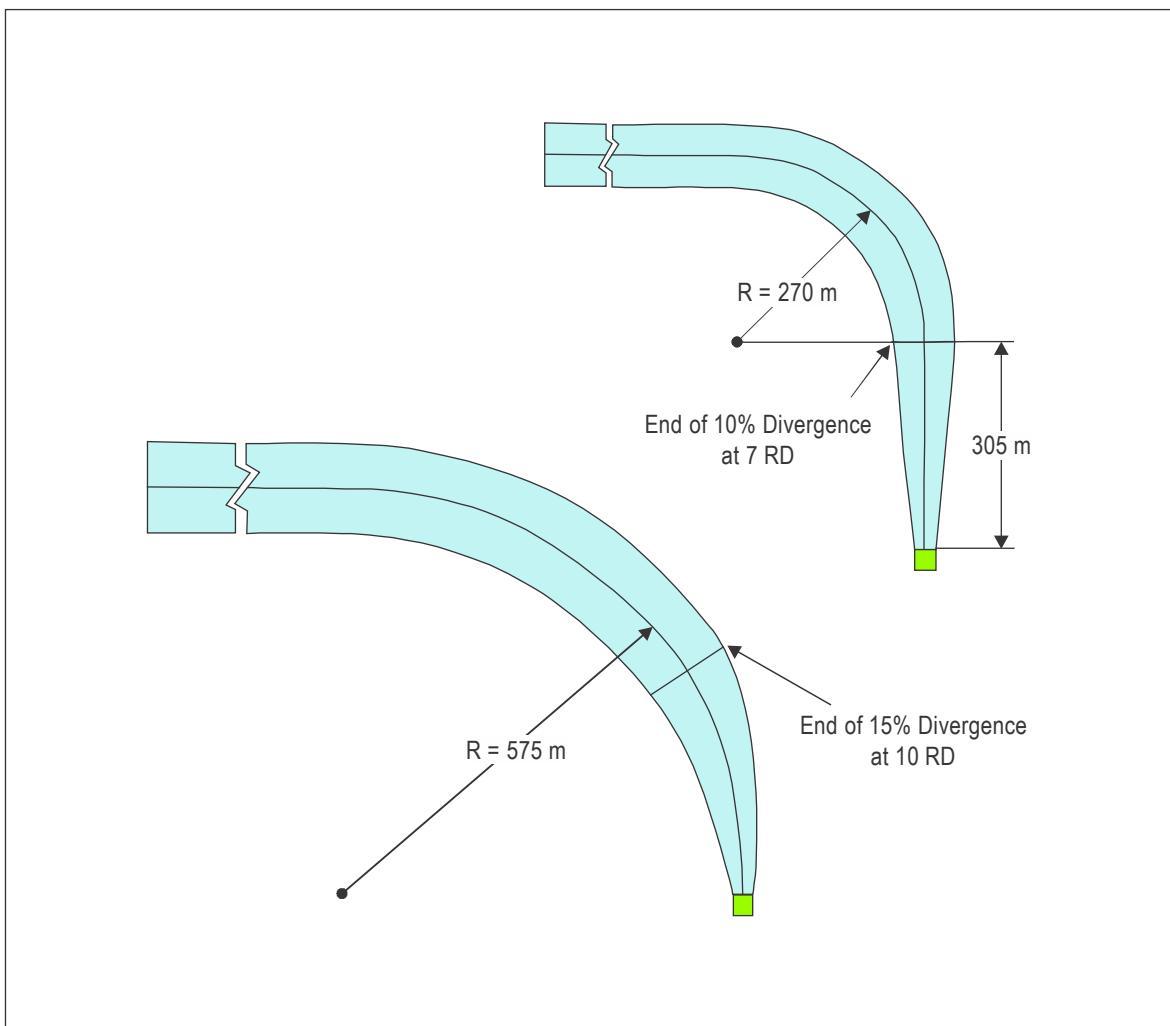
Figure II-4-1. Curved approach and take-off climb surface for all FATOs
4.1.1.7.3 In the case of an approach or take-off climb surface involving a turn:
a) the lateral and vertical surfaces should be the same as those for a straight approach surface;
b) for Category B or C slopes, the surface should not contain more than one curved portion, which can be placed anywhere on the length of the approach or take-off climb surface when meeting the conditions in 4.1.1.7.4 and 4.1.1.7.5 below; and
c) for Category A slopes, more than one curved portion, separated by a straight section of more than 150 m, is permitted.
4.1.1.7.4 The sum of the radius of arc defining the centre line of the approach surface and the length of the straight portion originating at the inner edge should not be less than 575 m. Any combination of curve and straight portion may be established using the following formula:
S+R ≥575 m and R ≥ 270 m where S = 305 m
where S is the length of the straight portion and R is the radius of tum.
4.1.1.7.5 Because helicopter take-off performance is reduced in a turn, a straight portion along the take-off climb surface prior to the start of the curve should be considered for type B and C slopes; this will permit an AEO acceleration to achieve a stable climb attitude and speed before a turn is initiated. For a PC 1 heliport with a type A slope, the helicopter should be in a stable OEI climb before the end of the TODAH prior to reaching the OLS. Limits on bank angle and degradation of turns on performance in accordance with the RFM should be noted and applied to the design helicopter.
Note.— At a PC 1 heliport with a type A slope, without an elevated OLS origin, operations in PC 2 and 3 can make use of the length of the TODAH to achieve a stable climb attitude and speed prior to reaching the OLS.
4.1.1.7.6 In lower than visual meteorological conditions (VMC), it may be difficult for a pilot to identify the boundaries or centre line of curved take-off climb or approach paths unless flown as a coupled approach. In the absence of such assistance, curved take-off and approach paths should be restricted to operations in VMC only.
4.1.1.8 Blending the spaces between the approach
or take-off climb surface and safety area
(see Figures II-4-2 to II-4-5)
Note.— The reference circle is an inscribed circle inside the FATO/SA that is used for orienting the approach/take-off and climb surface, transition area and helicopter clearway.
4.1.1.8.1 Areas between the inner edge of the approach or take-off climb surface and the safety area, if any, should have the same characteristics as the safety area, since it would be unacceptable for such areas to have characteristics that were below the standards of either of the adjoining surfaces.
4.1.1.8.2 Figures II-4-2 to II-4-4 illustrate such areas by shading the relevant portions, but these are, of necessity, shown only for the basic configurations of FATO and safety area and are not drawn to scale. However, the planned direction of the approach surface may not be located in line with, or at a convenient 45° to the centreline of the FATO. Furthermore, the FATO, and thus the safety area, may be of irregular shape or be much larger than one which can only just accommodate a circle of the minimum specified dimensions.
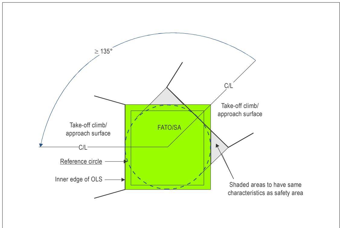
Figure II-4-2. Square FATO with reference circle and surfaces separated by 135⁰
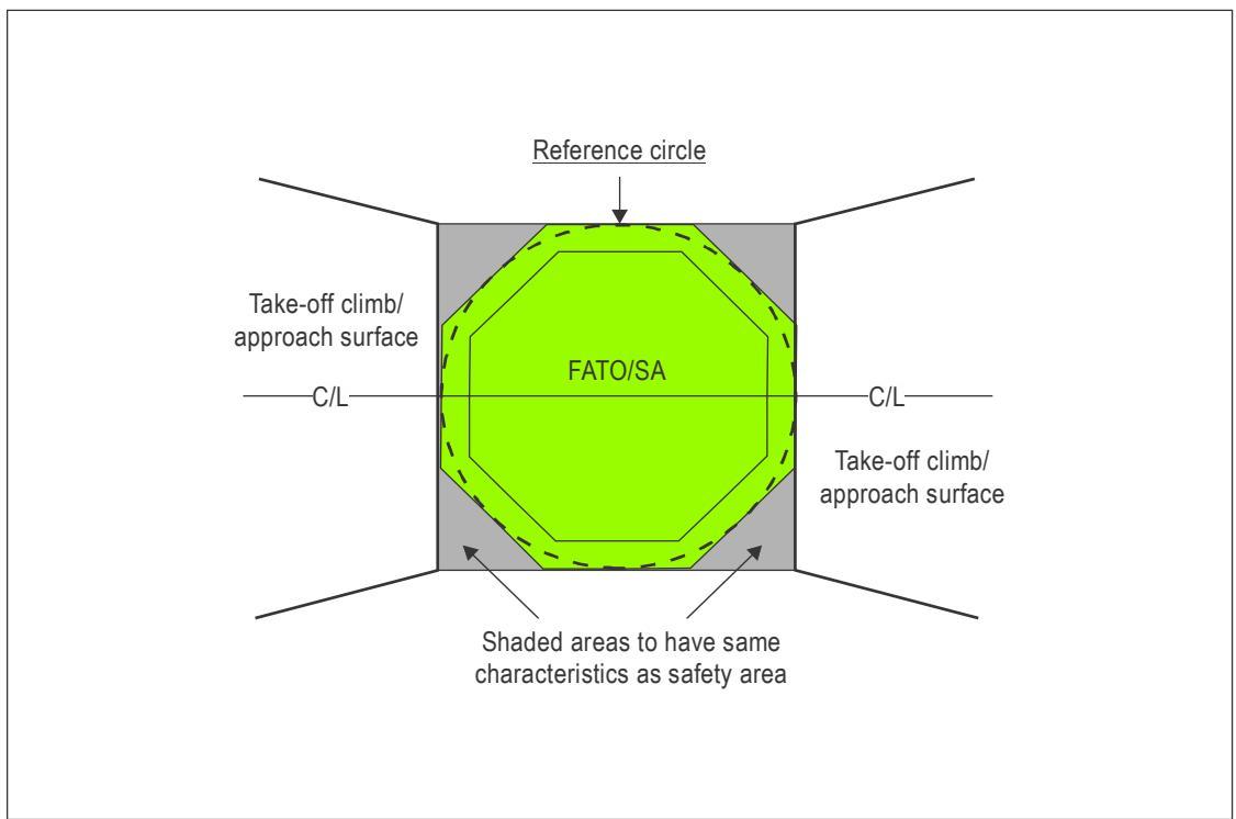
Figure II-4-3. Octagonal FATO with reference circle and diametrically opposed surfaces
4.1.1.8.3 The issues involved with such deviations from the basic configurations are:
a) where the inner edge should be located; and
b) the shapes and sizes of the shaded areas may vary considerably.
4.1.1.8.4 To identify the shaded areas, if any, it is necessary to consider their side edges as extending from the ends of the inner edge to points where they meet the tangent of the reference circle at right angles to the centre line of the surface. The shaded areas will then be bounded by these side edges, the inner edge and the edges of the safety area.
4.1.1.8.5 Where the FATO is elongated, there should be two reference circles within the safety area, each located at the appropriate approach end of the safety area (see Figure II-4-4).
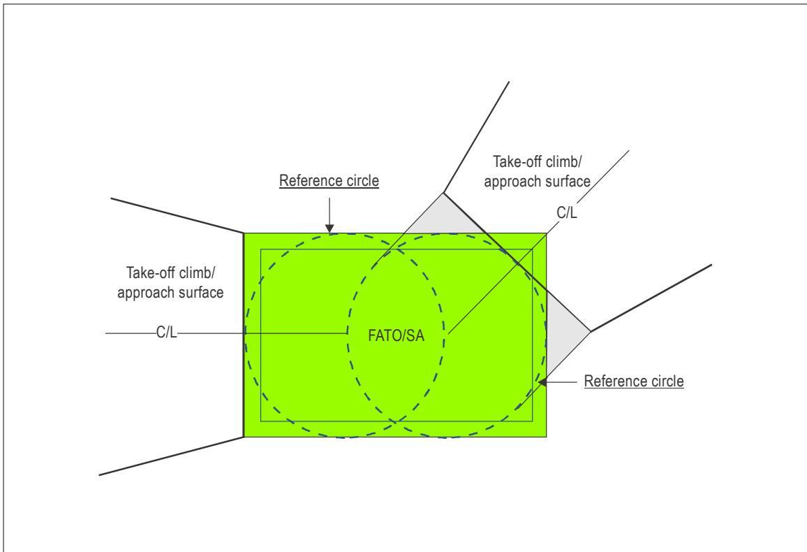
Figure II-4-4. Rectangular FATO two reference circles and surfaces separated by $1 3 5 ^ { \circ }$
4.1.1.8.6 Where a helicopter clearway has been established, the shaded area should be between the FATO/SA and helicopter clearway (see Figure II-4-5); the inner edge of the approach or take-off climb surface will abut with the helicopter clearway.
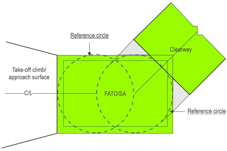
Figure II-4-5. Rectangular FATO two reference circles and helicopter clearway
4.1.1.9 Number and separation of take-off and climb and approach surfaces
4.1.1.9.1 Heliport design and location should be such that downwind operations are avoided, crosswind operations are kept to a minimum and balked landings can be carried out with the minimum change of direction.
4.1.1.9.2 The heliport should have at least two take-off and climb and approach surfaces with a recommend separation of at least $\boldsymbol { 1 3 5 ^ { 0 } }$ (see Figure II-4-2) but ideally separated by 180⁰. Additional approach surfaces may be provided, the total number and orientation ensuring that the heliport usability factor will be at least 95 per cent for the helicopters the heliport is intended to serve. These criteria should apply equally to surface level and elevated heliports.
4.1.1.9.3 Where the aforementioned objectives cannot be met, the separation may be decreased or the number of take-off and climb and approach surfaces reduced to one in accordance with Appendix B to Chapter 4.
4.1.1.10 Slope design categories
4.1.1.10.1 The slope design categories in Table II-4-1 should not be restricted to a specific performance class and may be applicable to more than one. The categories depicted represent minimum design slope angles and not operational slopes. Consultation with helicopter operators will help to determine the appropriate slope category to apply according to the heliport environment and the helicopters the heliport is intended to serve.
4.1.1.10.2 Slope Category A generally corresponds with helicopters operated in PC 1 and characterizes the limited performance that is available with one engine inoperative. Acceleration to $\mathsf { V } _ { \mathsf { t o s s } }$ and a positive rate of climb is normally achieved over a helicopter clearway.
Note.— The Category A slope is associated with an engine-failure in the take-off phase of flight for a helicopter operating in PC1 (Annex 6 — Operation of Aircraft requires operators to provide departure contingency procedures). It is likely to be paired with a superimposed Category B or C slope from the helicopter clearway, or immediately above the safety area (see Figures II-4-28 to II-4-32). Engine failure before 152 m (500 ft) might result in an aborted departure except in the case of operations where return to the heliport would not be a feasible option.
4.1.1.10.3 Slope Category B corresponds with helicopters operated AEO. The first section slope permits acceleration to the best rate-of-climb speed whilst remaining outside the avoid area of the height velocity diagram after which the second section slope is applied.
Note.— The length of the first section equates to a generic equivalent to the RFM AEO take-off distance to 15 m (50 ft).
4.1.1.10.4 Slope Category C corresponds with helicopters operated AEO and characterizes a helicopter with sufficient performance to permit both acceleration and climb at the required slope.
4.1.1.10.5 Helicopters operating in all performance classes can meet the constraints of a Category C slope in the approach phase.
Table II-4-1. Approach and take-off climb slope design categories
| Surface and dimensions | Slope design categories | ||
| A | B | C | |
| Approach and take-off climb surface: | |||
| Length of inner edge | Width of safety area | Width of safety area | Width of safety area |
| Location of inner edge | Safety area boundary | Safety area boundary | Safety area boundary |
| (Clearway boundary if provided) | |||
| Divergence: (1st and 2nd section) | |||
| Day use only Night use | 10% | 10% | 10% |
| 15% | 15% | 15% | |
| First section: | |||
| Length | 3386m | 245m | 1220m |
| Slope | 4.5% | 8% | 12.5% |
| Outer width | (1:22.2) | (1:12.5) | (1:8) |
| (b) | N/A | (b) | |
| Second section: | |||
| Length | N/A | 830m | N/A |
| Slope | N/A | 16% | N/A |
| Outer width | N/A | (1:6.25) (b) | N/A |
| Total length from inner edge (a) | 3386mc | 1075mc | 1220mc |
| Transitional surface: | |||
| Slope | |||
| Height | 50% (1:2) | 50% (1:2) | 50% |
| 45md | 45md | (1:2) 45 md | |
| a. | The approach and take-of climb surface lengths of 3 386 m, 1 075 m and 1 220 m associated with the respective slopes brings the helicopter to 152 m (500 ft) above FATO elevation. | ||
| b. Seven rotor diameters overallwidth for day operations or 10 rotor diameters overall width for night operations. | |||
| C. | This length may be reduced if verical procedures are in place or increased if the approach surface is extended to meet the OCS of the PinS arrival/departure procedure. | ||
| d. See Appendix A to Chapter 4, 2.1.1 | |||
4.1.2 Approach surface (see Figure II-4-6)
Note.— For an approach surface with an elevated origin, see Appendix A to Chapter 4.
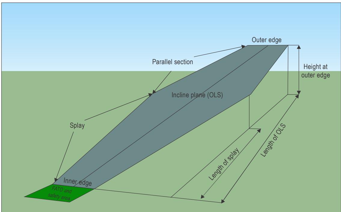
Figure II-4-6. Generic approach/take-off climb surface
4.1.2.1 Description. An inclined plane or a combination of planes or, when a turn is involved, a complex surface sloping upwards from the end of the safety area and centred on a line passing through the centre of the FATO or the diameter of the reference circle.
4.1.2.2 Characteristics. The limits of an approach surface should comprise:
a) an inner edge, horizontal and equal in length to the minimum specified width of the FATO plus the safety area, perpendicular to the centre line of the approach surface and located at:
-
for a runway type FATO - the outer edge of the safety area; or
-
for other than a runway type FATO - the outer edge of the reference circle;
b) two side edges originating at the ends of the inner edge:
-
for a FATO with a PinS approach procedure utilizing a PinS approach procedure with proceed visually instruction - diverging uniformly at a specified rate from the vertical plane containing the centre line of the FATO; or
-
for a FATO other than with a PinS approach procedure with proceed visually instruction, diverging uniformly at a specified rate from the vertical plane containing the centre line of the FATO to a specified width and continuing thereafter at that width for the remaining length of the approach surface; and
c) an outer edge horizontal and perpendicular to the centre line of the approach surface at a specified height above the elevation of the FATO.
4.1.2.3 The elevation of the inner edge should be the elevation of the safety area at the point on the inner edge that is intersected by the centre line of the approach surface.
4.1.2.4 The slope(s) of the approach surface should be measured in the vertical plane containing the centre line of the surface.
4.1.3 Transitional surface (see Figure II-4-7)
Note.— For take-off climb and approach surfaces with elevated origins see Appendix A to Chapter 4.
4.1.3.1 General
4.1.3.1.1 A FATO with a PinS approach/departure procedure with proceed visually instruction may be used in conditions that are below those required for VFR flight. Consequently, seeing and avoiding obstacles that are outside the OLS whilst manoeuvring to maintain the required flight path add to the workload of the pilot.
4.1.3.1.2 For the safety of a helicopter which becomes displaced from the centre line while executing a PinS approach/departure procedure with proceed visually instruction, a transitional surface should be provided, although not a necessity for heliports which will only be used in VMC.
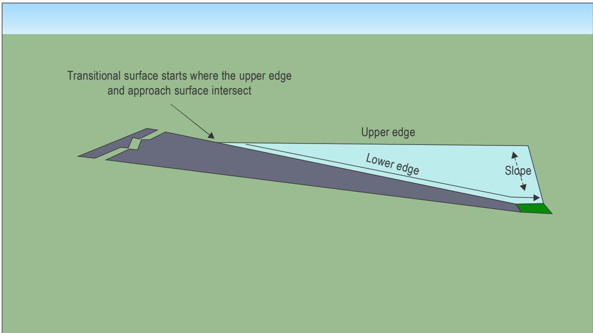
Figure II-4-7. Transitional surface
4.1.3.2 Description. A complex surface bounded by a lower and upper edge and sloping upwards and outwards from one to the other (see Figure II-4-7 and Appendix A to Chapter 4).
4.1.3.3 Characteristics. The limits of a transitional surface should comprise:
a) a lower edge beginning at the point where the approach surface and upper edge of the transitional surface are at the same height, then extending downwards and along the side of the approach surface to the inner edge of the approach surface and from there along:
-
for a runway-type FATO the length of the side of the safety area parallel to the centre line of the FATO; or
-
for other than a runway-type FATO, along the tangent of the reference circle parallel, and equal in length, to its diameter.
b) an upper edge located at a specified height above the FATO.
4.1.3.4 The elevation of the lower edge should be:
a) along the side of the approach surface, equal to the elevation of the approach surface at that point; and
b) along the safety area or tangent to the reference circle, equal to the elevation of the plane of the FATO, taking account of any drainage slope.
4.1.3.5 The transitional surface should have a slope of 50 per cent (1:2) (see Table II-4-1) measured in the vertical plane at right angles to the centre line of the FATO.
4.1.4 Take-off climb surface (see Figure II-4-6)
Note.— For a take-off climb surface with an elevated origin see Appendix A to Chapter 4.
4.1.4.1 During the take-off climb manoeuvre, far more power is required from the helicopter engines than is required during the descent or an approach to the hover or landing. If, during the take-off or climb phases, one engine becomes inoperative, even greater power is required from the remaining engine. However, in many helicopter types, the single engine is unable to supply the power required to sustain the best rate of climb obtainable with both engines operative, and so a lower rate and angle of climb must be accepted.
4.1.4.2 Description. An inclined plane, a combination of planes or, when a turn is involved, a complex surface, sloping upwards from the end of the safety area or helicopter clearway and centred on a line passing through the centre of the FATO.
4.1.4.3 Characteristics. The limits of a take-off climb surface should comprise:
a) an inner edge horizontal and equal in length to the minimum specified width of the FATO plus the safety area, perpendicular to the centre line of the take-off climb surface and located at:
-
for a runway type FATO - the outer edge of the safety area;
-
for other than a runway type FATO - the tangent of the outer edge of the ‘reference circle’; or
-
the outer edge of the helicopter clearway;
b) two side edges originating at the ends of the inner edge and diverging uniformly at a specified rate from the vertical plane containing the centre line of the FATO to a specified final width and continuing thereafter at that width for the remaining length of the approach surface; and
c) an outer edge horizontal and perpendicular to the centre line of the take-off climb surface and at a specified height above the elevation of the FATO.
4.1.4.4 The elevation of the inner edge should be the elevation of the safety area at the point on the inner edge that is intersected by the centre line of the take-off climb surface except that when a helicopter clearway is provided, the elevation should be equal to the highest point on the ground on the centre line of the helicopter clearway (for a take-off climb surface with an elevated origin, see Appendix A to Chapter 4).
4.1.4.5 The slope should be measured in the vertical plane containing the centre line of the surface.
4.2 APPLICATION OF OBSTACLE LIMITATIONS
4.2.1 General
4.2.1.1 The obstacle limitation requirements for ground level and elevated heliports will be the same. For elevated heliports, the specified surfaces should be defined relative to the horizontal plane at the elevation of the FATO.
4.2.1.2 The following obstacle limitation surfaces should be established for a FATO at a heliport other than one with a PinS approach/departure procedure with proceed visually instruction:
a) take-off climb surface; and
b) approach surface.
4.2.1.3 The following obstacle limitation surfaces should be established for a FATO at a heliport with a PinS approach/departure procedure with proceed visually instruction:
a) take-off climb surface;
b) approach surface; and
c) transitional surface.
4.2.1.4 The dimensions of the take-off climb approach surfaces should be considered in two parts.
4.2.1.4.1 In the first part, the lateral edges of the surface diverge from the direction of the centre line by 10 per cent each side for daylight operations and 15 per cent each side for night operations (see Figures II-4-8 and II-4-9). The divergence should extend until the over-all width of the surface has reached, for daylight operations 7, and for night operations 10,times the rotor diameter of the design helicopter. The increase in divergence and width at night is to allow for lack of visual references.
4.2.1.4.2 In the second part, the width of the surface should remain constant at the 7 or 10 rotor diameter dimensions, as appropriate.
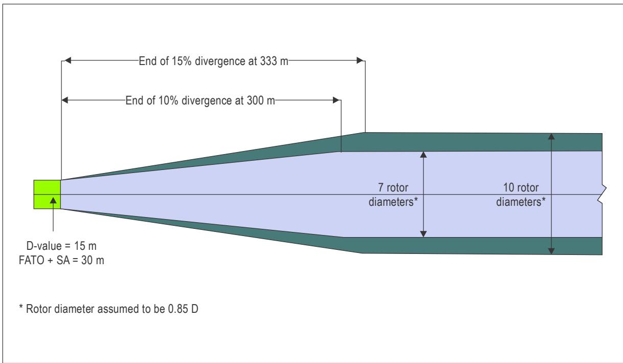
Figure II-4-8. Take-off climb/approach widths (to scale with 15 m D-value)
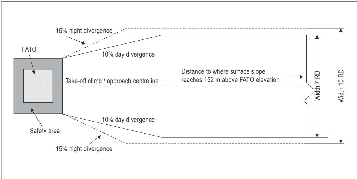
Figure II-4-9. Take-off climb/approach widths (schematic)
4.2.2 Approach surface for a FATO without a PinS approach/departure procedure with proceed visually instruction (see Figure II-4-10)
Note.—For a heliport with an approach surface with an elevated origin, see Appendix A to Chapter 4.
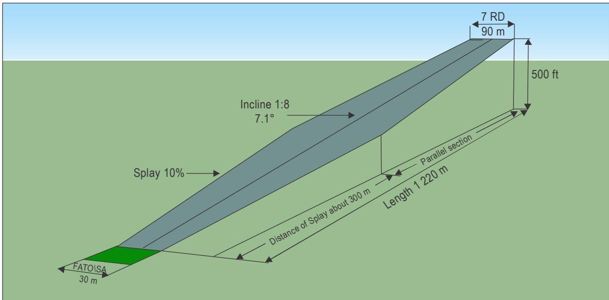
Figure II-4-10. Day approach surface without a PinS approach/departure procedure with proceed visually instruction (15 m D-value)
4.2.2.1 The slope should be 12.5 per cent until the surface reaches a height of 152 m (500 ft) above the elevation of the inner edge.
4.2.3 Approach surface for a FATO at a heliport with a PinS approach/departure procedure with proceed visually instruction
Note.— For a schematic view of a PinS direct-VS with descent point from the Procedures for Air Navigation Services — Aircraft Operations (PANS-OPS, Doc 8168), see Figures II-4-12 and II-4-14. For a 3D scaled representation of the procedure with an OLS divergence of 15 per cent and a MAPt/DP of 228 m (750 ft), see Figures II-4-13 and II-4-15.
4.2.3.1 Annex 14, Volume II, permits a minimum OLS final width of 7 RD by day and 10 RD by night. In parallel, Figure II-4-14 taken from the PANS-OPS shows an instant narrowing of the obstacle clearance surface (OCS) at the MAPt from for example, RNP 0.3, 1480 m (0.8 NM) to 120 m (half width 740 m to 60 m). It is therefore recommended that:
a) the lateral edges of the OLS should diverge by 15 per cent for the length of the surface;
b) the surface should extend to the height of the PinS OCS then level out and continue horizontally until it reaches the OCS at the DP; and
c) the slope of the surface should be 12.5 per cent until levelling out (see 4.1.1.10.5).
Note.— Other slope design categories may be used.
4.2.3.2 The transitional surface should (see Figures II-4-7 and II-4-11):
a) extend along the sides of the approach surface to a height of 45 m above the elevation of the FATO; and
b) slope upwards and outwards by 50 per cent from the lower edge until it reaches the upper edge at a height of 45 m (150 ft).
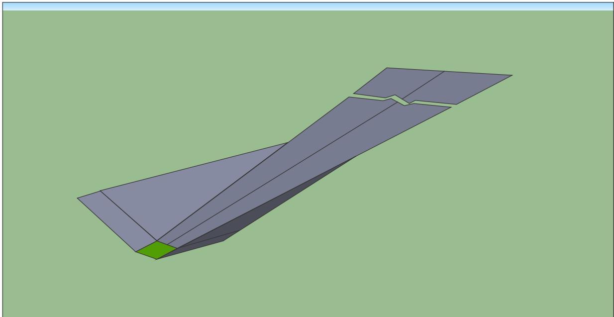
Figure II-4-11. Recommended approach surface for a PinS approach/departure procedure with proceed visually instruction (schematic)
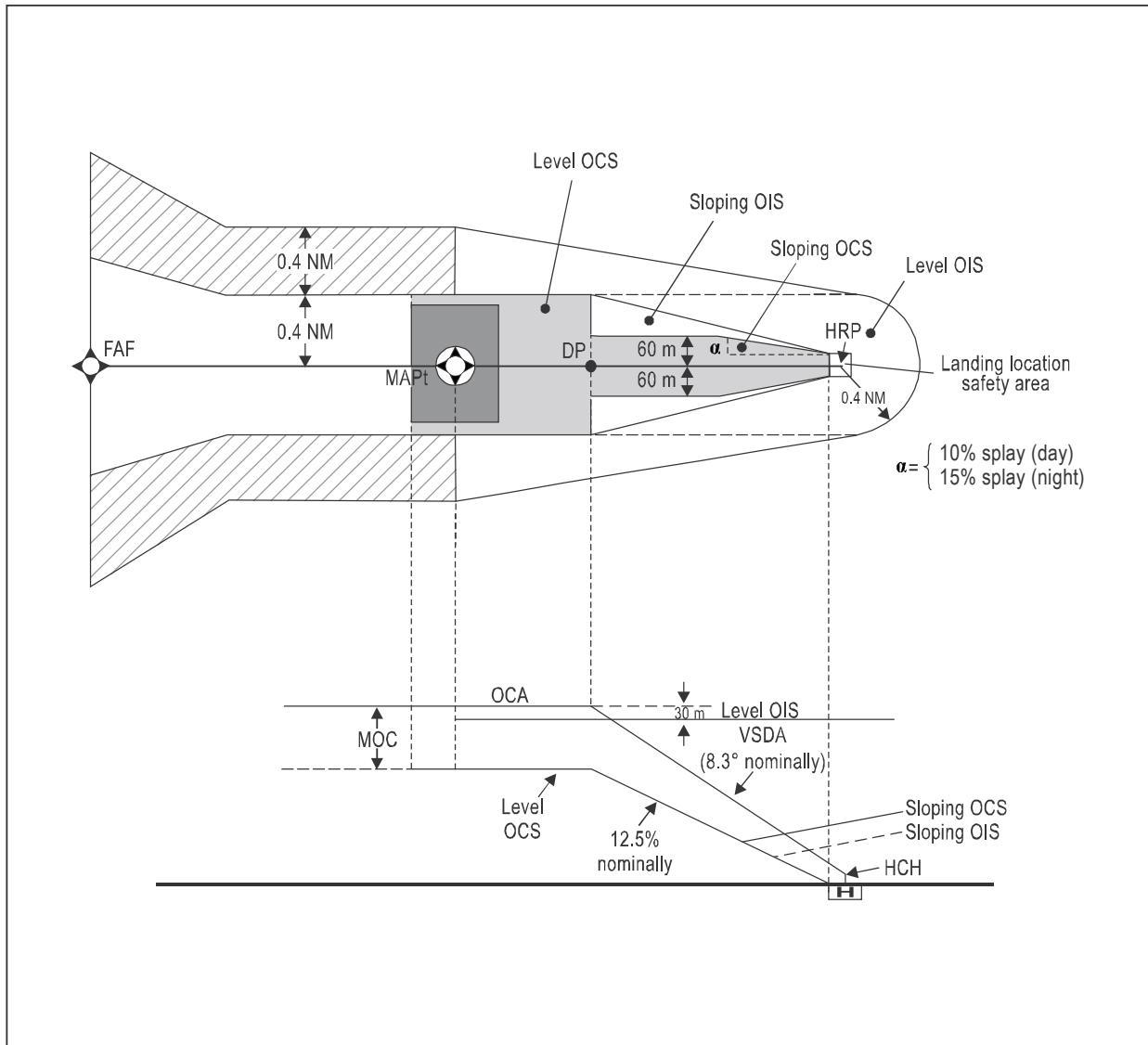
Figure II-4-12. Direct-VS with DP (schematic)
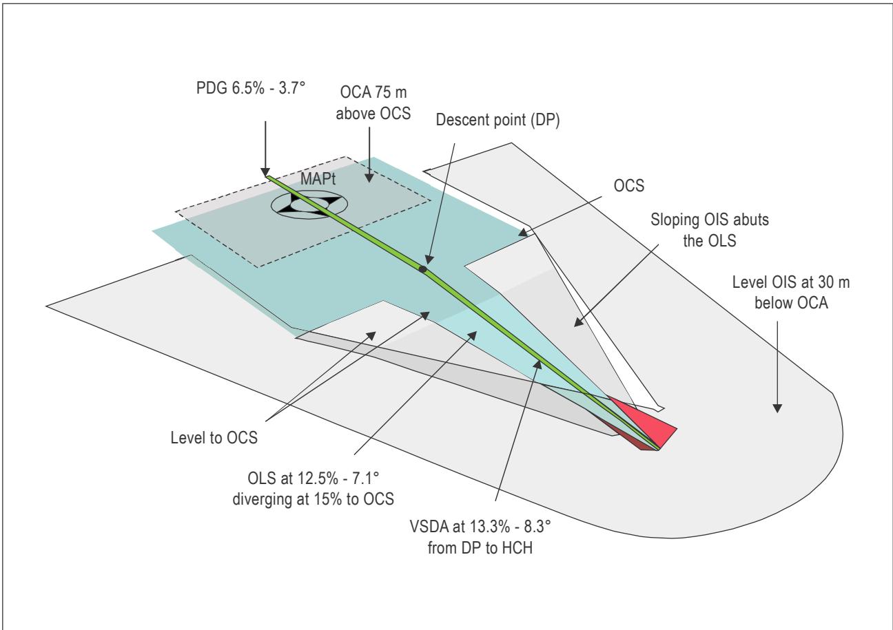
Figure II-4-13. Direct-VS with a full 15 per cent divergence, DP at 228 m (750 ft) and OCS at 152 m (500 ft)
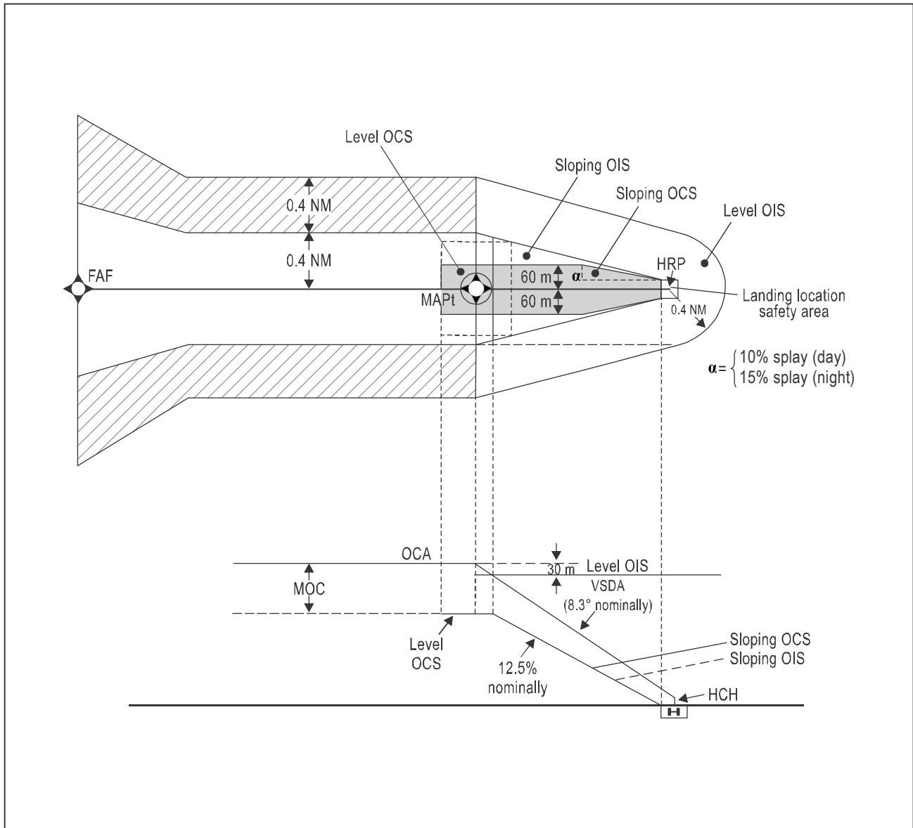
Figure II-4-14. Direct-VS (schematic)
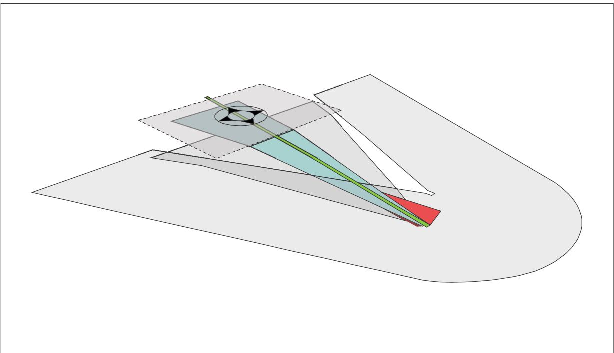
Figure II-4-15. Direct-VS with a full 15 per cent divergence, MAPt at 228 m (750 ft) and OCS at 152 m (500 ft)
4.2.4 Take-off climb surface for a FATO at a heliport without a PinS departure pocedure with proceed visually instruction
4.2.4.1 The divergence should be identical for all slope design categories as specified in 4.2.2.1 and 4.2.2.2.
4.2.4.2 The length of each design category should be the distance corresponding to a height of 152 m (500 ft) above the FATO elevation.
4.2.4.3 For a slope of design Category A, the slope of the surface should be 4.5 per cent and the total length from the inner edge, 3 386 m (1.8 NM) – see Figures II-4-16 and II-4-17.
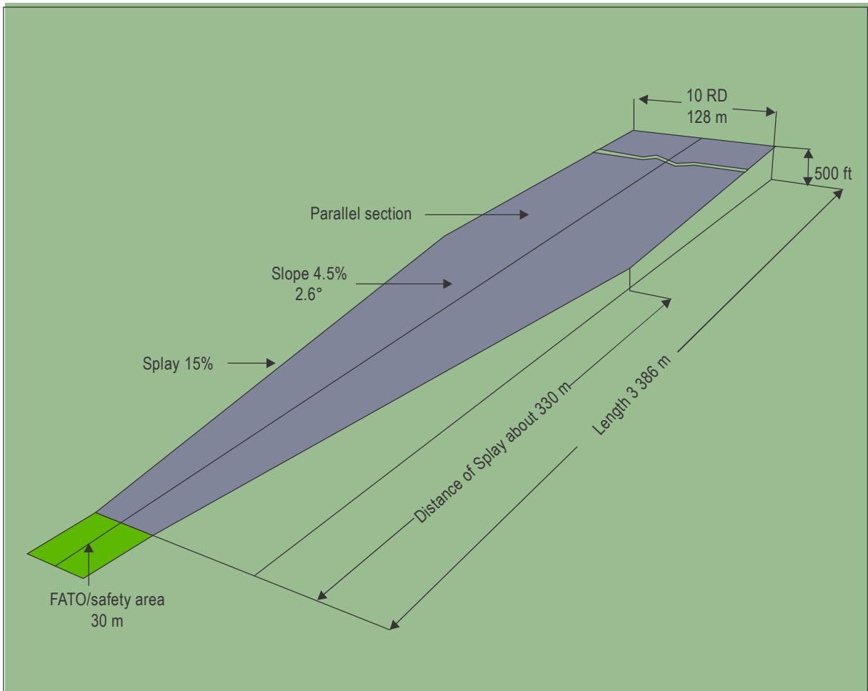
Figure II-4-16. Night category A slope (15 m D-value)
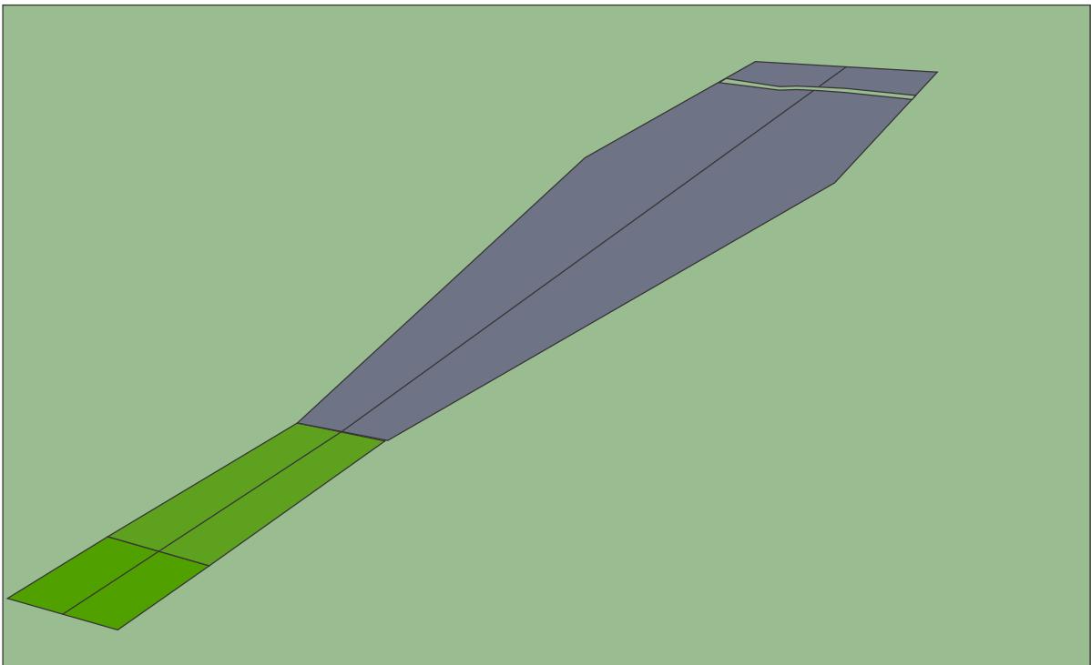
Figure II-4-17. Category A slope with helicopter clearway
4.2.4.4 For a slope of design Category B, the slope of the first section should be 8 per cent and the length from the inner edge, 245 m. The slope of the second section should be 16 per cent and the length from the end of the first section, 830 m. The total length from the inner edge should be 1075 m (0.58 NM), see Figure II-4-18.
4.2.4.5 For a slope of design Category C, the slope of the surface should be 12.5 per cent and the total length from the inner edge, 1 220 m (0.66 NM), see Figure II-4-19.
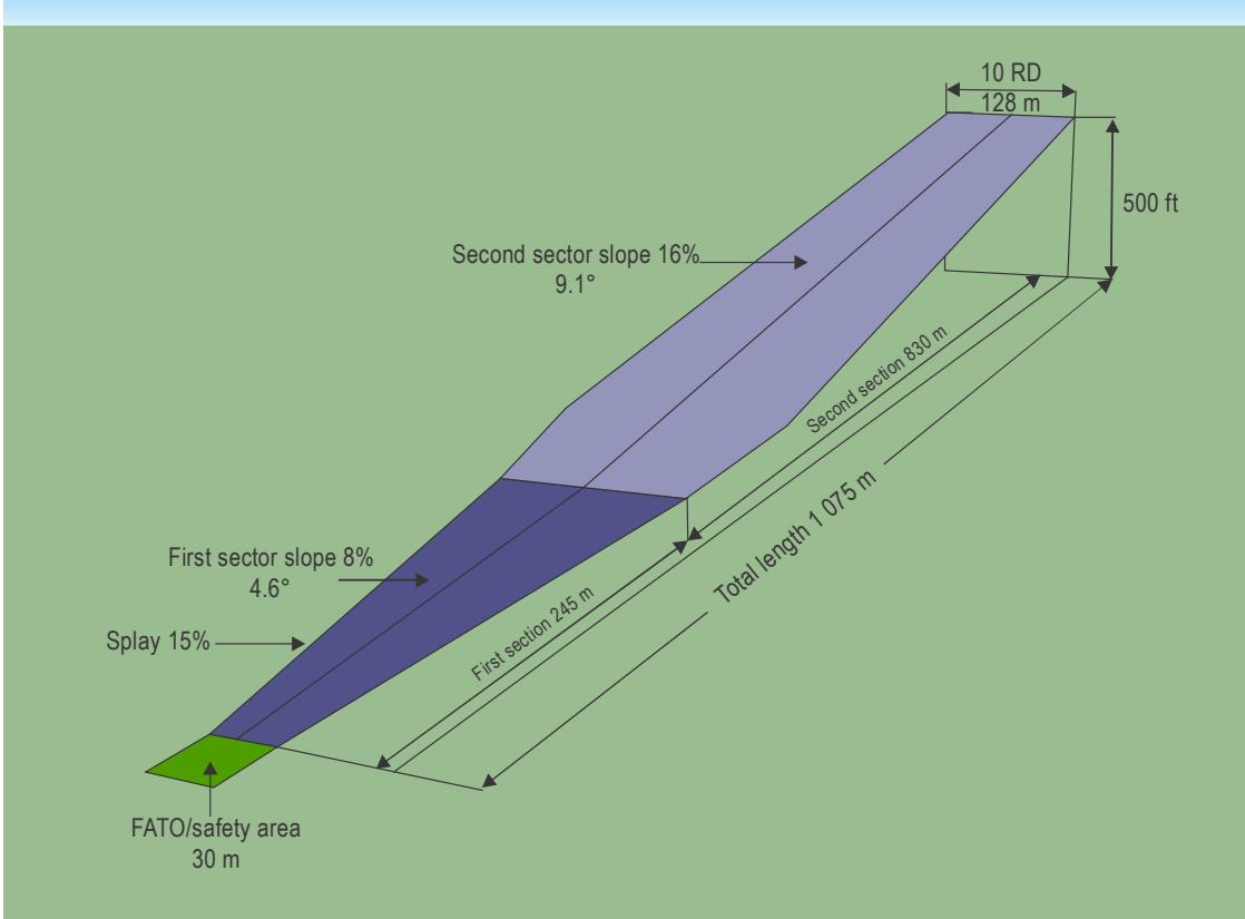
Figure II-4-18. Night Category B slope (15 m D-value)
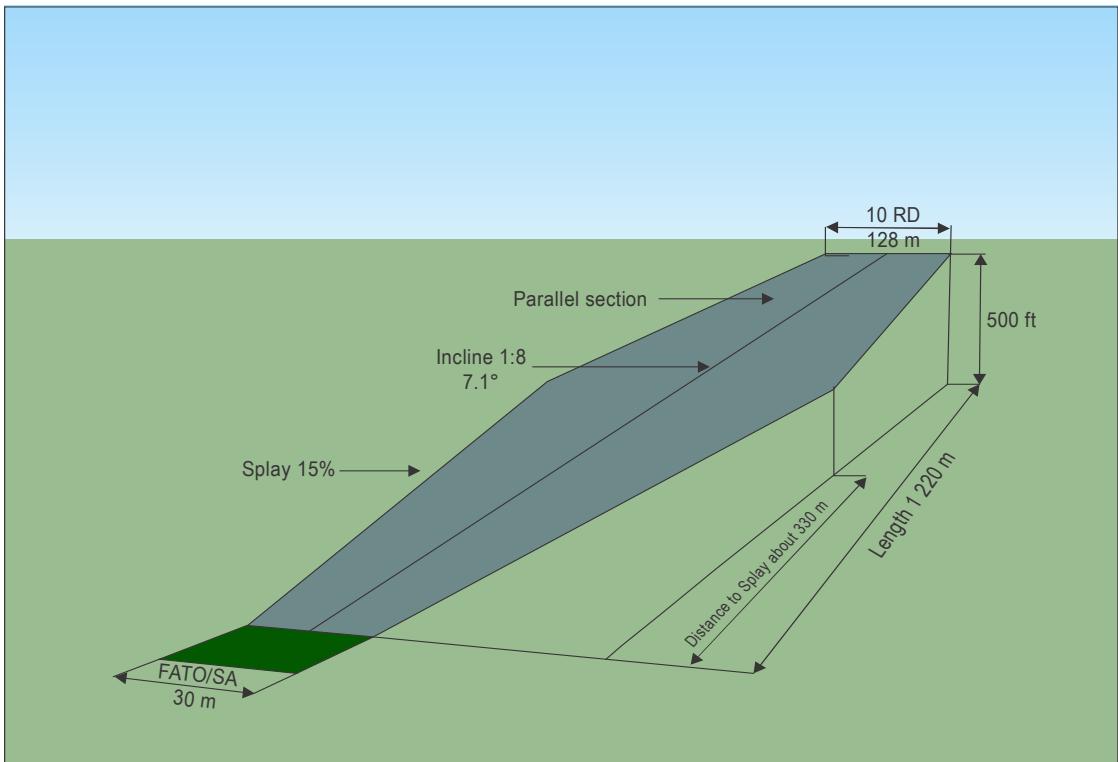
Figure II-4-19. Night Category C slope (15 m D-value)
4.2.5 Take-off climb surface for a FATO at a heliport with a PinS departure procedure with proceed visually instruction
Note.— For a 3D scaled representation of the procedure with an OLS (level OCS) divergence of 15 per cent, 12.5 per cent gradient, IDF of 198 m (650 ft) and RNP 0.3 dimensions, see Figure II-4-20.
4.2.5.1 Although Annex 14, Volume II, permits a minimum OLS width of seven rotor diameters by day, and 10 rotor diameters by night, it is recommended that:
a) the lateral edges of the OLS should diverge by 15 per cent for the length of the surface;
b) the OLS should extend to where it reaches a height of 30 m (100 ft) below the initial departure fix (IDF) minimum crossing altitude (MCA) then level out and continue horizontally to the position of the latest IDF; and
c) the slope of the OLS should be 12.5 per cent until levelling out.
Note.— Other slope design categories may be used.
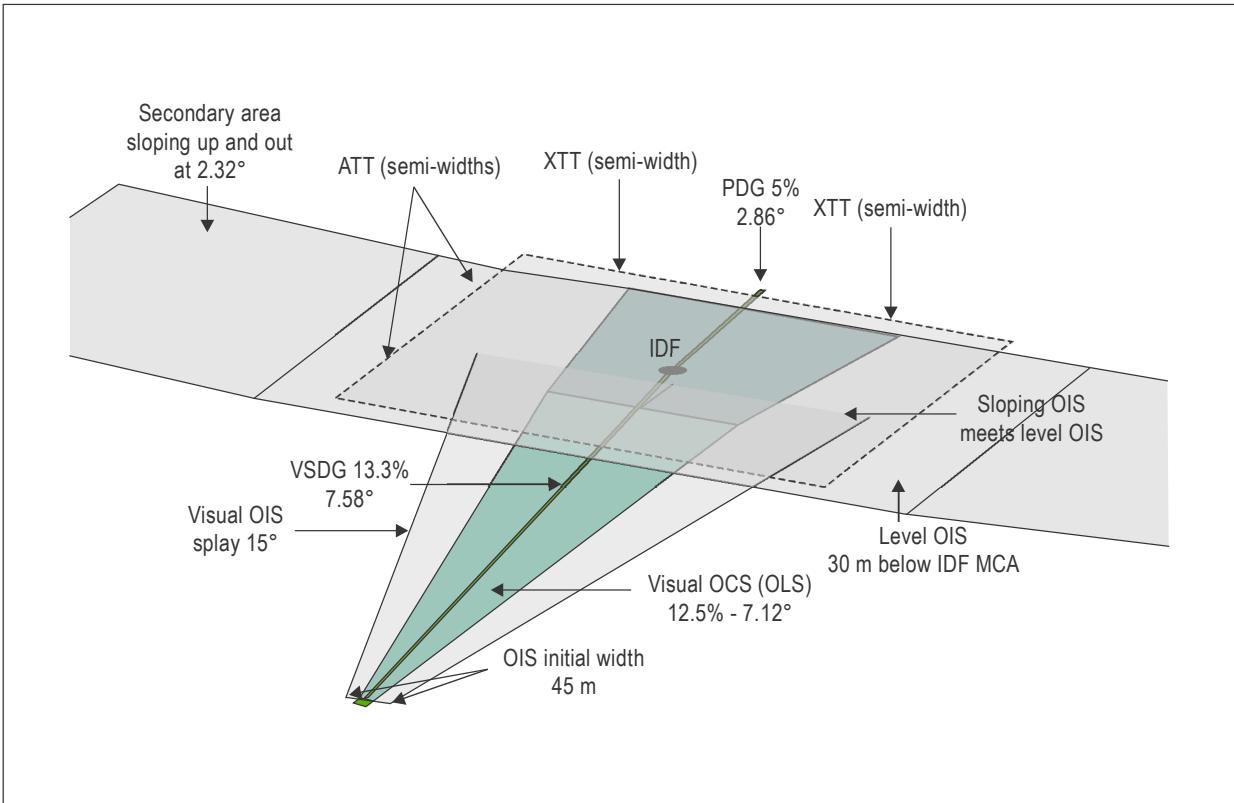
Figure 4-II-20. Direct-VS with 15 per cent divergence, 12.5 per cent gradient, IDF at 198 m (650 ft) and RNP 0.3 dimensions
ELEVATING THE ORIGIN OF THE TAKE-OFF CLIMB OR APPROACHSURFACES AND UTILIZING PC1 VERTICAL PROCEDURES
1. GENERAL
1.1 Elevating the take-off climb or approach surfaces achieves the criteria for the obstacle clearance by repositioning the origin of the take-off and climb surface above the obstacle environment (see Figures II-4-A-1 to II-4-A-5).
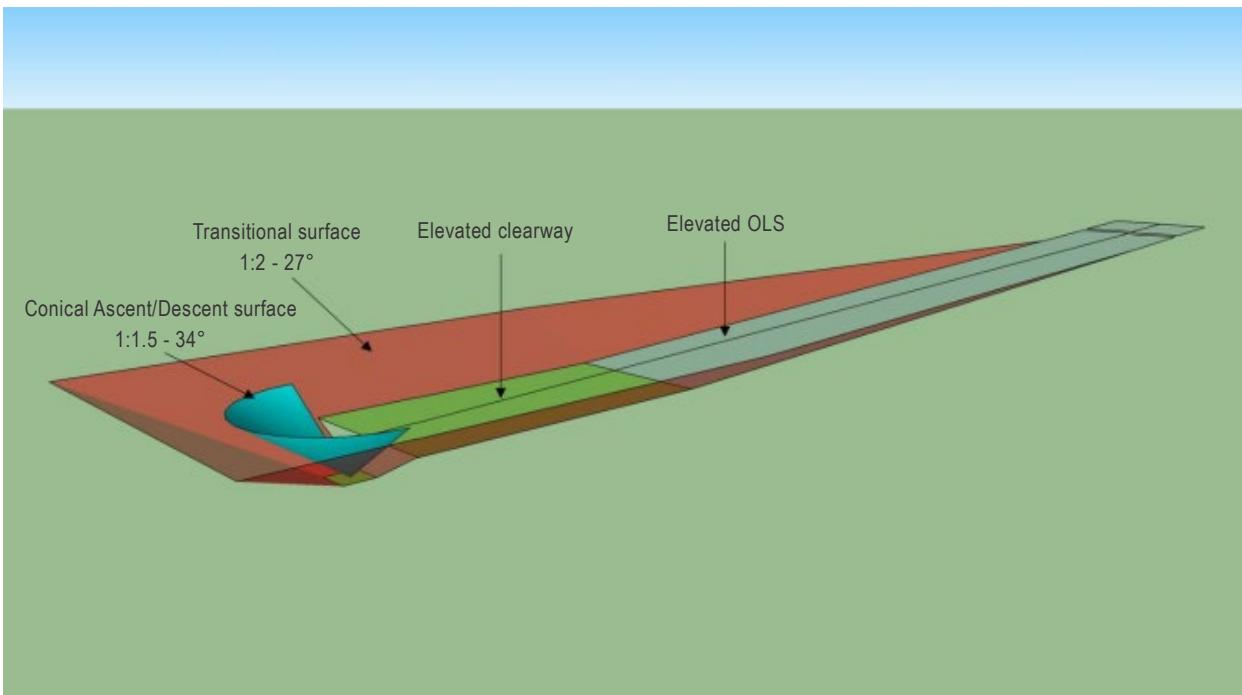
Figure II-4-A-1. Helicopter clearway and OLS raised by 30 m (100 ft) (oblique view)
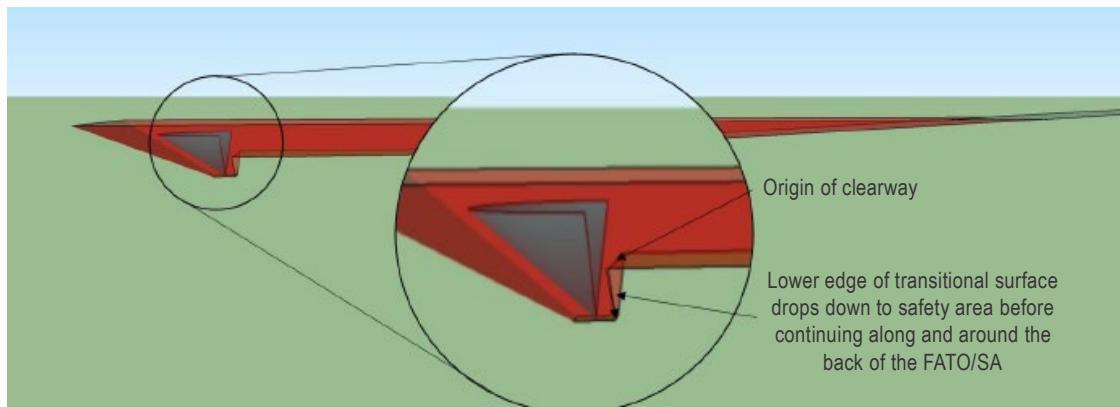
Figure II-4-A-2. Helicopter clearway and OLS raised by 30 m (100 ft) (side view)
1.2 Although a helicopter operating in PC1 can climb vertically with all engines operating, following an engine failure, it has limited ability to maintain height or climb until it attains its take-off safety speed or best rate of climb speed.
1.3 Manufacturers have overcome this potential weakness by utilising the AEO vertical climb performance to the TDP and increasing potential energy (in the form of height) whilst retaining the ability to reject the take-off and return to the heliport safely with OEI should an engine fail before the TDP.
1.4 At TDP, the available potential energy allows height to be converted into forward speed in the continued take-off, whilst accelerating to the take-off safety speed or OEI best rate of climb speed. Vertical clearance from obstacles is achieved by locating the TDP at a suitable height above the helicopter clearway. Where there are lateral and vertical elements, clearance from obstacles is facilitated by the widened helicopter clearway and the transitional surface (see Figure II-4-A-3).
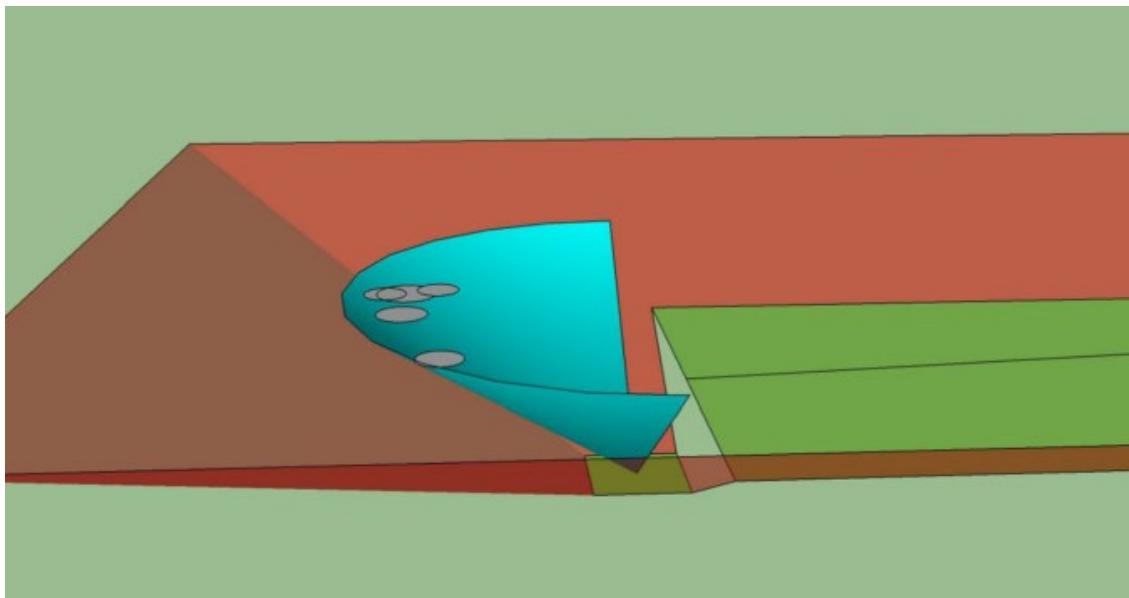
Figure II-4-A-3. Various types shown as D-size circles at their TDPs for an elevated helicopter clearway and OLS
1.5 This works in the opposite sense for the approach to a heliport with an elevated OLS (see Figure II-4-A-6). The helicopter slows from its approach speed arriving at the LDP with sufficient potential energy (height) to accelerate to best rate of climb speed and clear obstacles in a balked landing (in effect the helicopter clearway) or land OEI at the heliport.
1.6 The obstacle environment, origin and slope of the approach surface of a heliport utilizing elevated procedures are unlikely to be the same as those for the take-off climb surface. The heliport designer’s responsibility is to specify the obstacle limitation surfaces; the helicopter operator’s responsibility is to ensure that the procedures and flight profiles for take-off, landing and balked landing are specified accordingly.
Turns, as specified in 4.1.1.7 may be used (see Figure II-4-A4).
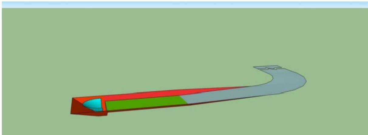
Figure II-4-A-4. Helicopter clearway and OLS raised with turn
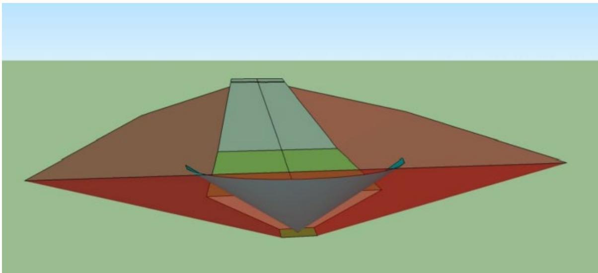
Figure II-4-A-5. Helicopter clearway and OLS raised by 30 m (100 ft) (looking along)
2. ELEVATING THE TAKE-OFF CLIMB SURFACE
The surfaces described below should be provided.
2.1 The OLS should have a category A slope.
2.2 When there is no lateral element (see Figure II-4-A-6):
a) the backup surface and ascent/descent path/surface described in Chapter 3, 3.2.4.4 (see also Figure 3.10); and
b) the helicopter clearway as described in 2.3.3 a) to c) with a width equal to the specified width/diameter of the FATO plus the safety area.
2.3 When there is a lateral element (see Figure II-4-A-1):
2.3.1 The transitional surface (the red surfaces) should:
a) establish the lateral boundary to obstacles surrounding the FATO and at the side of the helicopter clearway and OLS; and
b) be as specified in 4.1.3 above, except that the upper edge of the transitional surface should be extended vertically by the amount that the helicopter clearway and OLS are elevated, and the surface should continue around the back of the FATO/SA.
Note.— As can be seen from Figure II-A-4-2, at the origin of the helicopter clearway, the lower edge of the transitional surface descends down to the safety area before continuing along and around it.
2.3.2 The helicopter ascent/descent surface (the blue conical surface) should:
a) allow an AEO climb to the TDP (at the upper edge of the conical surface) remaining clear of obstacles whilst keeping the FATO in sight: and
-
for an engine failure up to and including the TDP, an OEI controlled descent clear of obstacles until landing at the FATO; or
-
for an engine failure at or after the TDP, an OEI continued take-off; and
b) with a transitional surface slope of 1:2 (260) be an inverted half-cone with a recommended slope of 1:1.5 (34⁰) with its origin at the centre of the reference circle and its upper edge no less than 30 m above the level of the helicopter clearway.
Note.— The divergence between slope of the ascent/descent surface and the slope of the obstacle limitation surface should be at least 12.5 per cent.
2.3.3 The helicopter clearway (the semi-transparent green surface) should:
a) establish the vertical boundary of permitted obstacles immediately below the take-off surface, above which the helicopter should remain whilst accelerating to its recommended climbing speed;
b) be as specified in Appendix D to Chapter 3;
c) be of sufficient length that it will permit the achievement of the TODRH for the population of helicopters for which the heliport is intended (300 m is recommended); and
d) be of sufficient width that it meets the surface of the transitional slope at the specified height above the FATO –i.e. with a transitional surface of 50 per cent, it is extended on each side at twice the height of the elevation.
Note.— With a clearway elevation above 30 m (100 ft), the width of the take-off climb surface may exceed 10 rotor diameters.
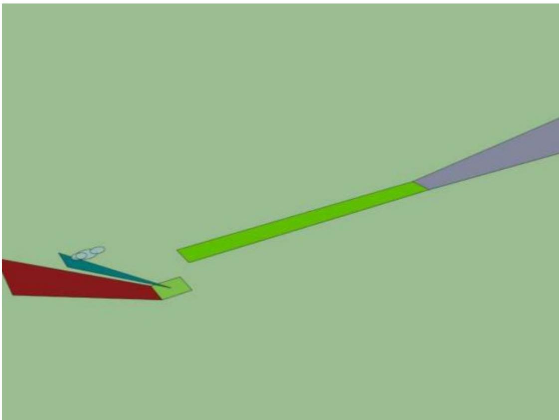
Figure II-4-A-6. Helicopter clearway and OLS raised by 30 m (100 ft) without lateral element)
3. ELEVATING THE APPROACH SURFACE
Note 1.—The approach flight path and the location of and/or conditions (speed/height) at the LDP are operational issues. The LDP can be anywhere on the approach flight path prior to, or at, the ascent/descent surface. The conditions up to the LDP should be such that initiation of a balked landing will not result in a descent below: the approach path; and 11 m (35 ft) above obstacles in the balked landing path (when the balked landing is conducted over an existing take-off path, the minimum height will be the height of the elevated clearway plus 11 m (35 ft). If the approach and takeoff climb surfaces are separated a turn may be required; the LDP should therefore be at a point where a balked landing can be conducted safely.
Note 2. — Passing the LDP (the last point at which a balked landing can be initiated) represents a commitment to land regardless of where the LDP is situated. As the helicopter approaches the ascent/descent surface, it will be in a decelerative phase to the point where the correct altitude, speed, and attitude, for the descent down to the FATO, is attained (for a true vertical descent, this will be in the hover, for other profiles there will be a defined, residual ground speed).
Note 3. — The backup and ascent/descent surfaces for the arrival will normally be those provided for the departure; when there is separation, these surfaces should be reoriented to the approach heading. When there is a lateral element, the transitional surface will be effective only prior to penetration of the backup protection surface.
3.1 The approach surface should have a Category C slope (a gradient of 12.5 per cent) with its inner edge at, or (nominally) directly above the outer edge of the safety area.
Note. — Nominally, because the approach surface will be intersected by the backup (obstacle limitation) surface provided to protect the ascent/descent path (see Figure II-A-4-9).
3.2 The inner edge of the approach surface should be elevated to a height providing obstacle clearance in the approach.
3.3 When there is a lateral element (see Figures II-4-A-7 and II-4-A-8);
a) the conical ascent/descent surface should be centred on the approach heading;
b) the upper edge of the transitional surface should be extended vertically by the amount that the OLS is elevated; and
c) the inner edge of the approach surface should be of sufficient width to meet the surface of the transitional slope at the specified height above the FATO.
Note. — When the origin is elevated above 100 ft, the width of the approach surface may exceed 10 rotor diameters.
3.4 When there is no lateral element:
a) the backup surface and ascent/descent surface should be centred on the approach heading.
b) the inner edge of the approach surface should be the width of the FATO and safety area (see Figure II-4-A-9);
3.5 If the upper edge of the approach surface is located at 152 m (500 ft), the overall length will be reduced.
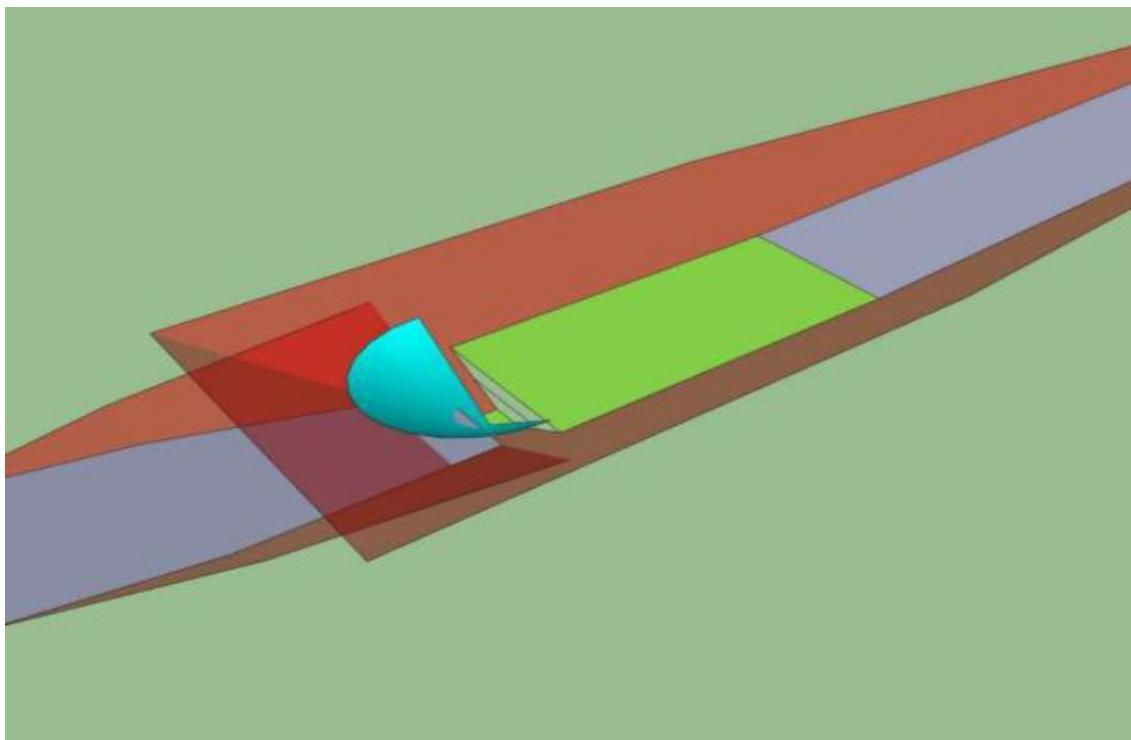
Figure II-4-A-7. Approach surface to 15 m (50 ft with lateral element)
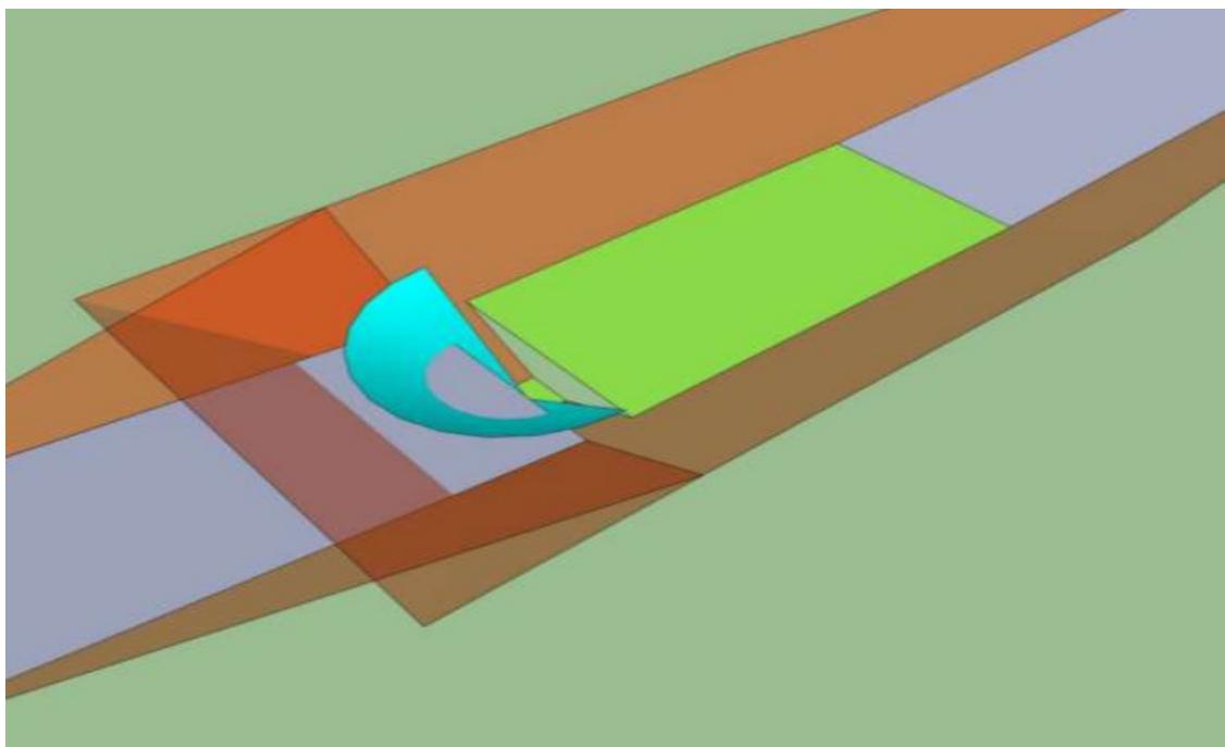
Figure II-4-A-8. Approach surface elevated to 30 m (100 ft) (with lateral element)
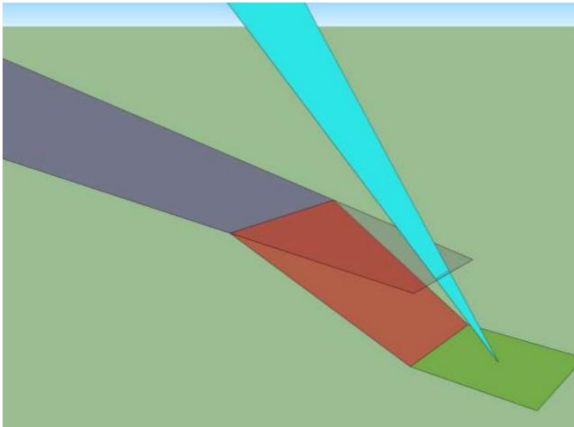
Figure II-4-A-9. Approach surface (without lateral element)
4. VERTICAL PROCEDURES WITH LATERAL TRANSIT ON A SINGLE SIDE
In some urban environments, there may be a need to operate close to obstacles that prevent symmetrical application of obstacle clearance, for example, buildings close to one side of the FATO/SA. This can be achieved safely with vertical procedures having a lateral element restricted to one side only as shown in Figures II-4-A-10 to 11-4-A12.
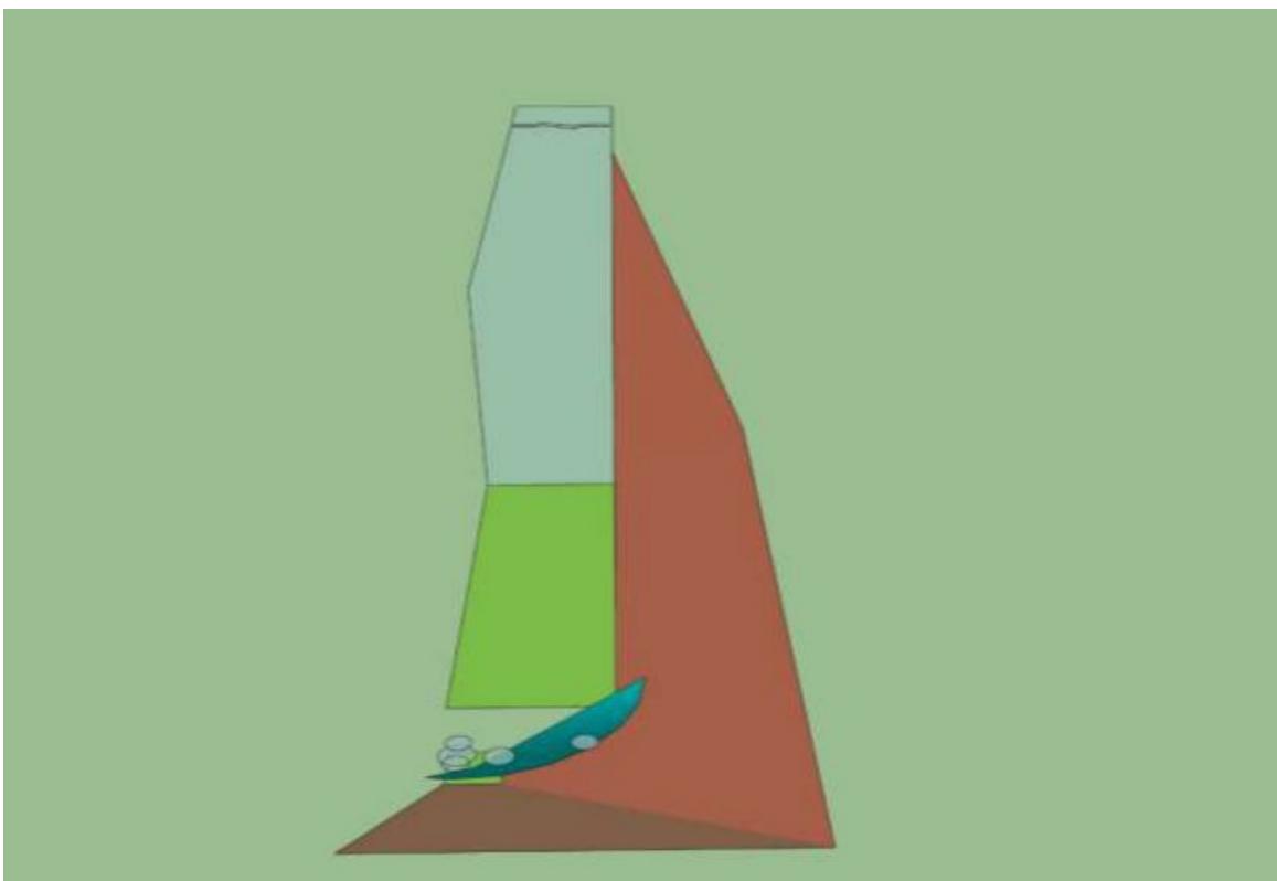
Figure II-4-A-10. Single side vertical (rear view)
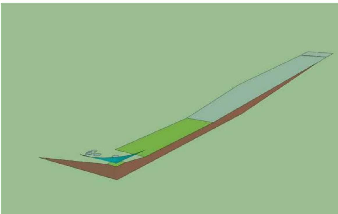
Figure II-4-A-11. Single side vertical procedure (oblique view)
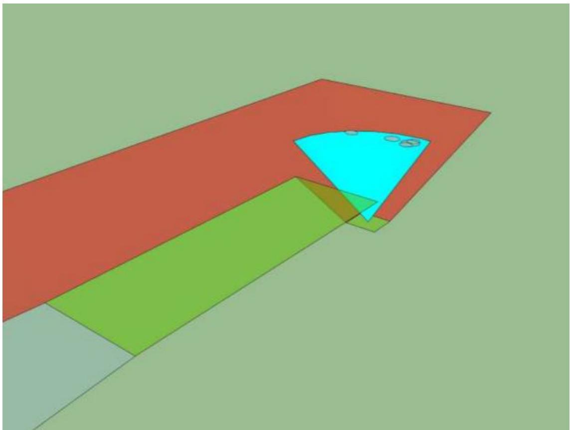
Figure II-4-A-12. Single side vertical procedure (front view)
Appendix B to Chapter 4
SINGLE TAKE-OFF AND CLIMB AND APPROACH SURFACE
To be completed in due course.
Chapter 5
VISUAL AIDS
Note 1.— The numbers and letters used in the illustrative figures of this chapter may not be of the form and proportion of numbers and letters shown in Figure II-5--6.
Note 2.— A heliport meant for use by day in VFR will need to display markings only. On the other hand, if the heliport is intended for use by night or in restricted visibility conditions by day or night it will need to be lighted as well. The marking and lighting aids described in this chapter support the Standards of Annex 14, Volume II, and have been developed primarily to support non-precision approaches and operations in visual meteorological conditions.
Note 3.— Before operations are conducted at night with night vision imaging systems (NVIS) into a heliport, it is important to establish the compatibility of the NVIS system with all heliport lighting. As not all NVIS are the same, compatibility should be assessed by the helicopter operator prior to use.
5.1 INDICATORS
5.1.1 Wind direction indicator. The wind direction indicator provides a visual indication of the wind direction and gives an indication of wind speed. Each heliport should be provided with at least one wind direction indicator.
5.1.2 An indicator should be a truncated cone as shown in Figure II-5-1. The cone should be of either a single colour (white or orange) or a combination of two colours (orange and white, red and white or black and white). The indicator should be sited to avoid the effects of turbulence and should be of sufficient size to be visible from helicopters flying at a height of 200 m. Where a touchdown and lift-off area may be subjected to a disturbed air flow, additional small lightweight wind vanes located close to the area may prove useful.
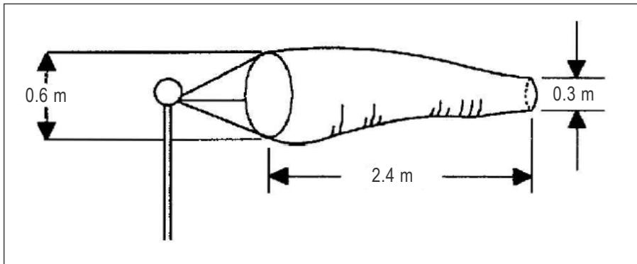
Figure II-5-1. Wind direction indicator
5.2 MARKING AIDS
The following markings will prove useful under the conditions specified for each aid at a heliport intended for operation by day:
a) heliport identification marking;
b) maximum allowable mass marking;
c) D-value marking;
d) final approach and take-off area perimeter marking or markers for surface level heliports;
e) final approach and take-off area designation marking for runway-type FATOs;
f) aiming point marking;
g) touchdown and lift-off area perimeter marking;
h) touchdown/positioning marking;
i) heliport name marking;
j) helicopter taxiway marking and markers;
k) helicopter air taxi-route markers;
l) helicopter stand marking;
m) flight path alignment guidance marking; and
n) obstacle marking.
5.2.1 Heliport identification marking
5.2.1.1 The heliport identification marking provides an indication of the presence of a heliport to the pilot by its form, likely usage and the preferred direction(s) of approach.
5.2.1.2 The marking consists of a white letter “H” (see Figure II-5-3) or, for a heliport located at a hospital, a red letter “H” on a white cross (see Figure II-5-4) with minimum dimensions as shown in Figure II-5-2. The marking is located at the centre of the final approach and take-off area or when used in conjunction with designation markings for a runwaytype FATO at each end of the area with the location and dimensions shown in Figure II-5-11.
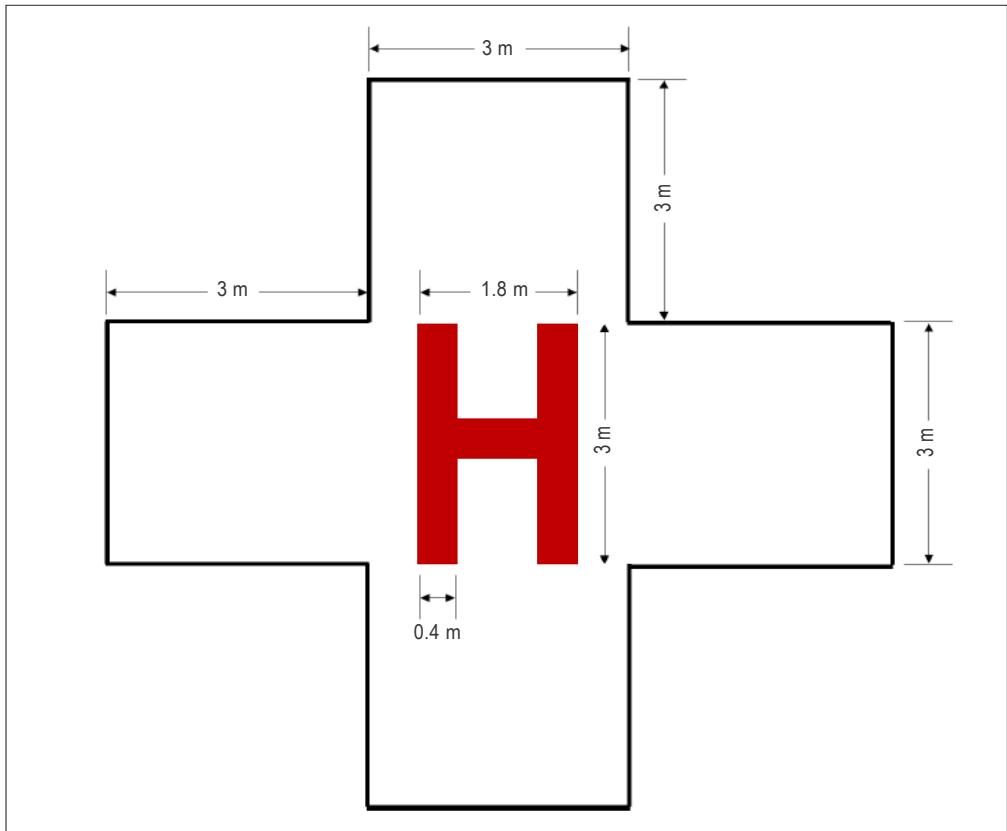
Figure II-5-2. Hospital heliport identification marking (dimensions)
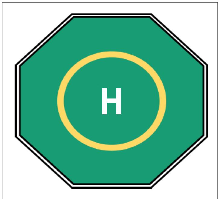
Figure II-5-3. Heliport identification marking with TDPC (location)
5.2.1.3 The heliport identification marking should be oriented with the cross arm of the H at right angles to the preferred final approach direction.
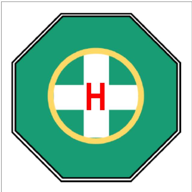
Figure II-5-4. Heliport identification marking with TDPC (hospital)
5.2.1.4 If the touchdown/positioning marking is offset, the heliport identification marking should be established in the centre of the offset TDPC as shown in Figure II-5-5.
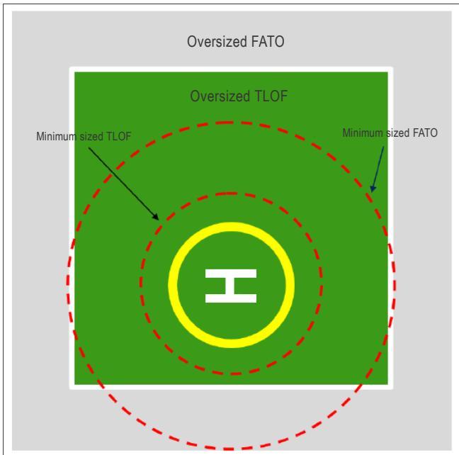
Figure II-5-5. Heliport identification marking (offset TD/PM)
5.2.2 Maximum allowable mass marking
5.2.2.1 The markings display the mass limitation of the heliport and make it visible to the pilot from the preferred final approach direction(s).
5.2.2.2 The display of the allowable maximum mass is derived from the design helicopter and is intended to ensure that only helicopters with a take-off or landing mass equal to or less than the maximum allowable mass use the heliport. The examples below show non-whole numbers and are there mainly to assist operators in understanding how their types fit into the designation.
Note.— The maximum allowable mass represents the limitation on a helicopter’s actual mass on arrival or departure and could be less than the MTOM of the type concerned.
5.2.2.3 The style and dimensions of the numbers and letters of the marking should correspond to those shown in Figure II-5-6. Representation of the maximum allowable mass should be:
a) when expressed in metric units, a two-digit number showing the mass to the nearest 1 000 kg (e.g. 03, 04 or 13), or two or three digit number with a decimal point showing the mass to the nearest 100 kg (e.g. 2.9, 3.6 or 12.6), followed by the letter “t” to indicate the mass in tonnes; and
b) when expressed in imperial units (United States), a two or three-digit number with a decimal point showing the mass rounded to the nearest 100 lbs, with 50 lbs rounded up (e.g. 15 750 lbs. marked as 15.8), without a letter suffix.
5.2.2.4 The following examples illustrate both methods using the mass of existing types (figures are for illustrative purposes only; they may have changed during the development of a helicopter type due to mass growth):
Sikorsky S92A:
Metric: MTOM 12 565 kg, would be 13t or 12.6t; or
Imperial: MTOM 28 000 lbs, would be 28.0.
EC 135T2:
Metric: MTOM 2 910 kg, would be 03t or 2.9t; or
Imperial: MTOM 6 400 lbs, would be 6.4.
A109:
Metric: MTOM 3 600 kg, would be 04t or 3.6t; or
Imperial: MTOM 6 000 lbs, would be 6.0.
5.2.2.5 Maximum mass markings should be displayed on the surface (TLOF or FATO) where they are readable from the preferred approach directions. The recommended locations are shown in Figure II-5-13.
5.2.2.6 When the maximum mass is in imperial units it should be shown in a box outlined in black. The numbers of the marking should have a colour contrasting with the background, preferably white, with the dimensions shown in Figure II-5-7. The box should be displayed on the lower right of the surface (TLOF or FATO) when viewed from the preferred approach direction.
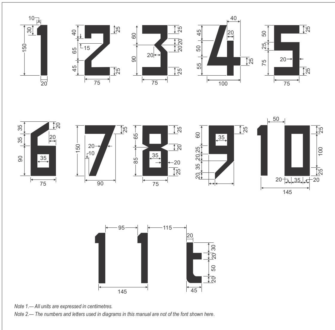
Figure II-5-6. Form and proportion of numbers and letters
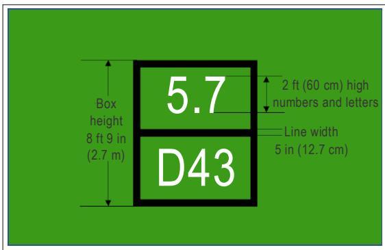
Figure II-5-7. Maximum mass and D-values shown in imperial units
5.2.3 D-value marking
5.2.3.1 The marking provides the pilot with the D-value of the largest helicopter that can be accommodated on the heliport. It is essential information for every heliport as it represents the value on which the standard sized TDPC, TLOF, FATO and stands are based.
Note.— Smaller stands with reduced sized TLOFs and TD/PMs are permitted.
5.2.3.2 The D-value is derived from the design helicopter and is displayed to ensure that only helicopters with a ‘D’ less than or equal to the D-value use the heliport. The numbers of the marking should have a colour contrasting with the background and should have the following characteristics:
a) for a D-value of less than 15 m, a minimum height of 60 cm, each with a proportional reduction in width and thickness;
b) for a D-value of 15 m to 30 m, a minimum height of 90 cm; and
c) for a D-value of 30 m or greater, a minimum height in accordance with Figure II-5-6.
5.2.3.3 The D-value should be expressed to the nearest whole number and displayed as whole metres without a letter prefix (metric) or the letter ‘D’ with dimensions in whole feet (imperial).
5.2.3.4 The following examples illustrate both methods using the ‘D’ of existing types:
Sikorsky S92A:
Metric: D of 20.88 m would be 21; or
Imperial: D of 68.49 ft would be D68.
EC 135T2:
Metric: D of 12.20 m would be 12; or Imperial: D of 40.00 ft would be D40.
A109:
Metric: D of 13.05 m would be 13; or Imperial: D of 42.80 ft would be D43.
5.2.3.5 The D-value marking should be displayed on the surface (TLOF or FATO) where it is readable from the preferred approach directions. The recommended locations are as shown in Figure II-5-13.
5.2.3.6 When the design-D is in imperial units it should be shown in a box outlined in black. The marking should have a colour contrasting with the background, preferably white, with the dimensions shown in Figure II-5-7. The box should be displayed on the lower right of the surface (TLOF or FATO) when viewed from the preferred approach direction.
5.2.4 Perimeter marking or markers for surface level solid FATO
5.2.4.1 The marking or markers provide, where the perimeter of the FATO is not self-evident, an indication of the area that is free of obstacles and in which the intended procedures, or permitted manoeuvring, may take place.
5.2.4.2 FATO markings or markers, when required, should be located at the edge of the FATO with the corners marked.
5.2.4.3 For a runway-type FATO, the spacing of the markings or markers should not exceed 50 m and:
a) the marking should be a rectangular white stripe with a length of 9 m, or one fifth of the side of the FATO which it defines, and a width of 1 m as shown in Figure II-5-8 (for guidance on the lighting elements see 5.3.7); or
b) the marker should be of the dimension shown in Figure II-5-9; the colour should contrast effectively against the operating background and be red-and-white (as shown), or a single colour of orange or red.
5.2.4.4 For other than a runway-type FATO:
a) the perimeter should be marked (for guidance on the lighting elements see 5.3.7):
-
when paved, by white dashed lines; or
-
when unpaved, by white flush in-ground markers as shown in Figure II-5-10; and
b) the FATO perimeter markings or marker segments should be 1.5 m in length and 30 cm in width with end spacing of not less than 1.5 m and not more than 2 m.
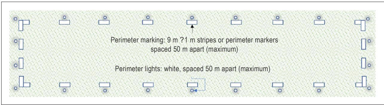
Figure II-5-8. Perimeter marking for runway-type FATO
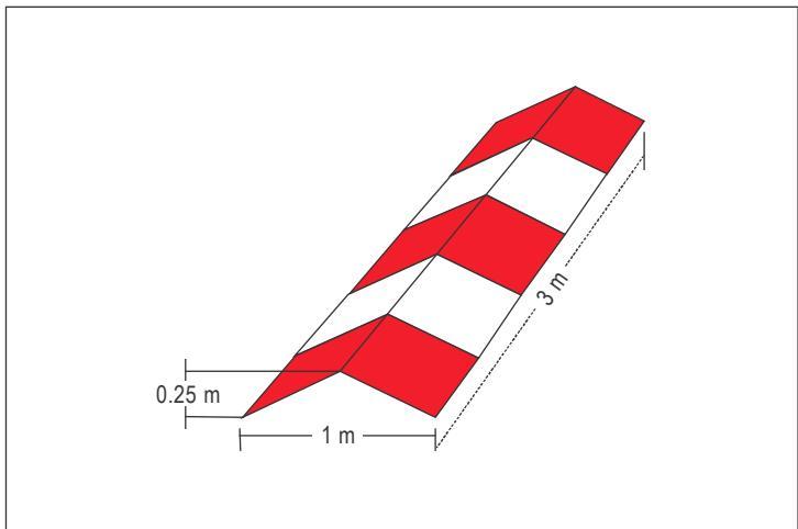
Figure II-5-9. Perimeter marker for runway-type FATO
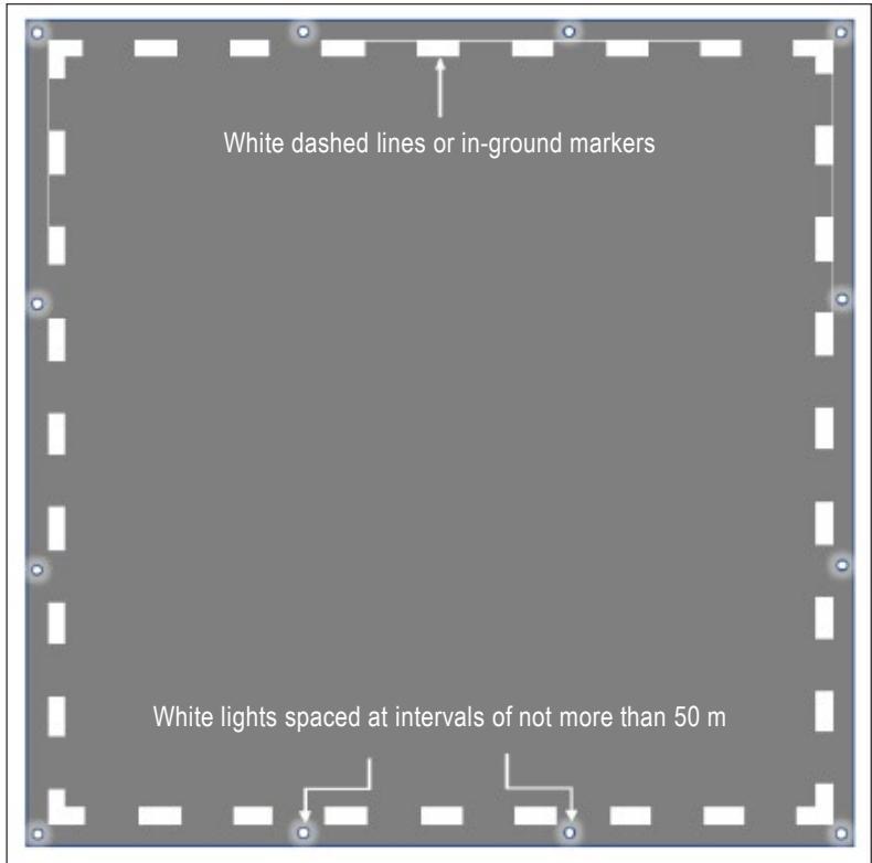
Figure II-5-10. Perimeter marking for other than a runway-type surface level FATO
5.2.5 Designation marking for runway-type FATOs
5.2.5.1 The designation marking for runway-type FATOs provides an indication of the magnetic heading of the FATO.
5.2.5.2 The marking identifies a particular FATO and should be displayed only where it is necessary to distinguish one FATO from another. The designation should be a two-digit number in the form and proportions shown in Figure II-5- 6. When the runway heading is a single-digit number, it should be preceded by a zero.
5.2.5.3 The marking should consist of the runway designation marking supplemented by a letter “H” as shown in Figure II-5-11.
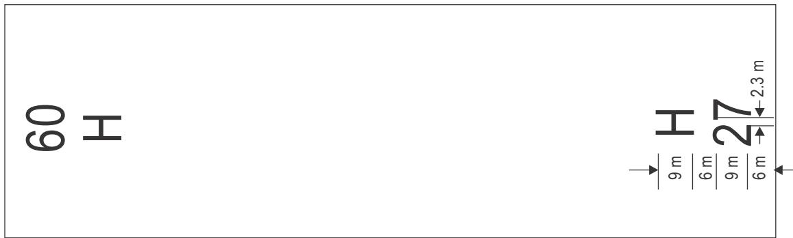
Figure II-5-11. Designation markings for runway-type FATO
5.2.6 Aiming point marking
5.2.6.1 The marking provides a visual cue indicating to the pilot:
a) the preferred approach/departure direction;
b) the point to which the helicopter approaches to the hover before positioning to a stand where a touchdown can be made; and
c) on a runway-type other than the FATO, that the surface is not intended for touchdown.
5.2.6.2 An aiming point marking should be displayed when it is intended for a pilot to make an approach to the hover at a particular point in the final approach and take-off area. The aiming point should be located:
a) for a runway-type FATO, at the termination point of the intended approach; and
b) for runway-type other than the FATO, at the centre of the FATO.
5.2.6.3 The marking should be an equilateral triangle with the dimensions shown in Figure II-5-12, and with the bisector of one of the angles aligned with the preferred approach direction. The sides of the triangle should be composed of continuous white lines, except for hospital sites where the lines may be red (to contrast with the white cross) as shown in Figure II-5-13.
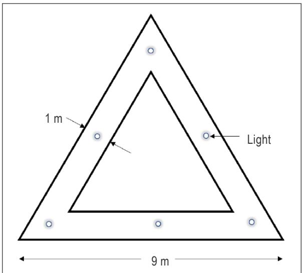
Figure II-5-12. Aiming point marking
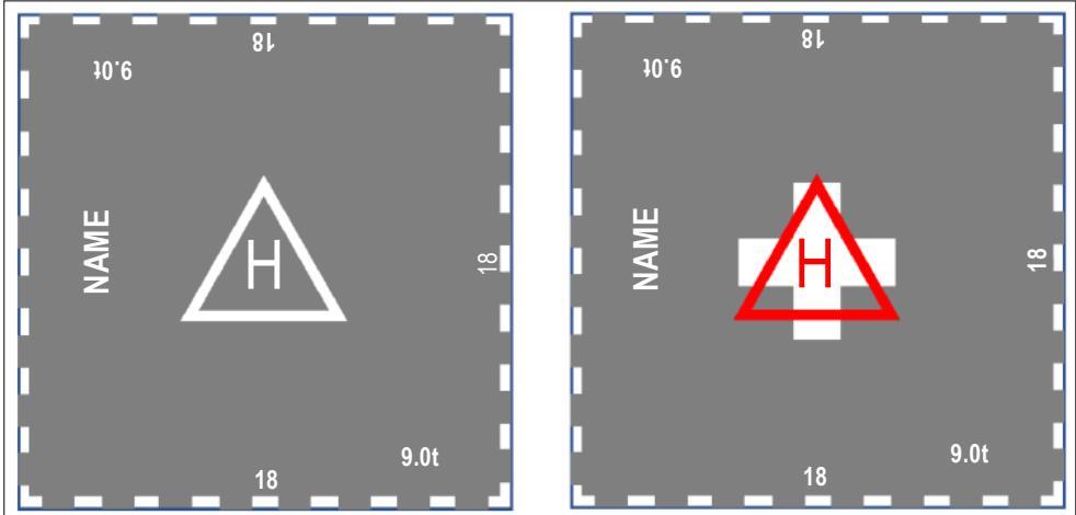
Figure II-5-13. Aiming point marking on a hover FATO
5.2.7 Touchdown and lift-off area perimeter marking
5.2.7.1 The touchdown and lift-off area perimeter marking provides the pilot with an indication of an area:
a) that is free of obstacles;
b) that has dynamic load bearing; and
c) in which, when positioned in accordance with the TD/PM, undercarriage containment is assured.
5.2.7.2 The marking should be located at the edge of the TLOF and consist of a continuous white line at least
30 cm wide.
5.2.8 Touchdown/positioning marking
5.2.8.1 The touchdown/positioning marking (TD/PM) provides visual cues which permit a helicopter to be placed in a specific position (touchdown), or manoeuvred (positioned), such that when the pilot’s seat is above the marking, the undercarriage is within the load-bearing area and all parts of the helicopter are clear of obstacles by a safe margin.
5.2.8.2 The TD/PM is critical to the design of heliports because it provides the visual cues on which containment is dependent.
5.2.8.3 The TD/PM is provided in two forms:
a) straight lines, sometimes accompanied by shoulder lines and radius curves (see Figure II-5-18); examples are:
-
a centre line in a taxiway;
-
a centre line with lead-in/lead-out lines and shoulder lines, in a taxi-through stand or restricted TLOF; or
-
a centre line with lead-in/lead-out lines, radius curves and shoulder lines in a stand; and
Note.— A TD/PM with straight lines indicates that turns are not permitted on that section. In 5.3, almost all figures showing the TLOF are shown with a TDPC; this is because it is the most likely to have a TDPC.
b) a touchdown positioning circle (TDPC) in a TLOF, exceptionally with a prohibited landing sector.
5.2.8.4 The TDPC should be a yellow circle with an inner diameter equal to: half the D of the D-value of the design helicopter (TLOF in a FATO – see Figure II-5-14); or, the largest helicopter for which the area is intended (TLOF in a stand).
5.2.8.5 The line width for TD/PMs for a heliport should be at least 0.5 m, but ideally 1 m.
5.2.8.6 The prohibited landing sector marking should be used when it is necessary to prevent the tail rotor being placed over a specific area, e.g. an ingress or egress point (see Figure II-5-15). The prohibited sector marking should be diametrically opposite from the avoid area and consist of hatched lines overlaying the TDPC and extending to the perimeter of the TLOF. The hatched-line width should be half the width of the TDPC line and be painted in red (it may be necessary to underpaint the marking to provide an adequate contrast).
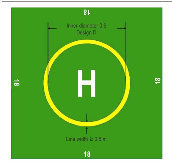
Figure II-5-14. Touchdown positioning circle (TDPC) dimensions
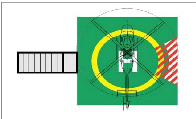
Figure II-5-15. Prohibited landing sector marking
5.2.9 Heliport name marking
5.2.9.1 The heliport name marking provides a means of identifying a heliport and can be seen and read from all directions of approach.
5.2.9.2 The name should only be provided if it there is insufficient alternative means of visual recognition.
5.2.9.3 When provided, the marking should consist of the name or the alphanumeric designator of the heliport as used in radio communications (R/T). The colour should contrast with the background and where possible be white and the characters of the marking should be:
a) for a runway-type FATO, not less than 3 m in height;
b) for a surface level FATO, other than a runway-type, not less than 1.5 m in height; and
c) for an elevated heliport, not less than 1.2 m in height.
Note— To allow for recognition of the facility further back in the approach, consideration should be given to increasing the character height of the heliport name marking from 1.2 m to 1.5 m.
5.2.9.4 Where the character height is 1.5 m, the character widths and stroke widths should be in accordance with Figure II-5-6. The character widths and stroke widths of nominal 1.2 m characters should be 80 per cent of those prescribed by Figure II-5-6. Where the heliport name marking consists of more than one word it is recommended that the space between words be approximately 50 per cent of character height.
5.2.10 Helicopter taxiway marking and markers
5.2.10.1 The helicopter taxiway markings and markers provide the pilot with visual cues to guide movement along the taxiway without being a hazard to the helicopter.
5.2.10.2 Helicopter taxiway centre line markings should be a continuous yellow line 15 cm in width. Unpaved surfaces which will not accommodate painted markings should be marked with flush in-ground yellow markers, 15 cm in width and 1.5 m in length, spaced at intervals of not more than 30 m on straight sections and not more than 15 m on curves, with a minimum of four equally spaced markers per curved section.
5.2.10.3 A centre line marking is all that is necessary to provide the pilot with visual cues to guide movement along the taxiway. Edge markings or markers should be used only when, for safety reasons, it is necessary to mark the boundaries of the taxiway.
5.2.10.4 Helicopter taxiway edge markings should be a continuous double yellow line each of 15 cm in width, spaced 15 cm apart. They should be located at 1 m to 3 m beyond the edge of the taxiway and should be retro-reflective blue. The marked surface as seen by the pilot should be a rectangle and have a minimum viewing area of 150 cm. Markers commonly used are cylindrical in shape. The design of the marker should be lightweight and frangible to the undercarriage and, when installed, should not exceed 25 cm total height above the mounting surface (see Figure II-5-16).
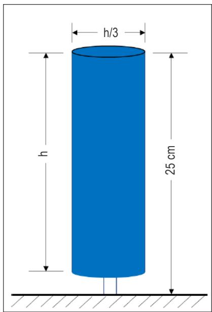
Figure II-5-16. Helicopter taxiway edge marker
5.2.11 Helicopter air taxi-route marking and markers
5.2.11.1 The helicopter air taxi-route markings and markers provide the pilot with visual cues to guide movement along the air taxi-route.
5.2.11.2 Where an air taxi-route is collocated with a taxiway, the centre line markings will be those of the taxiway.
5.2.11.3 Where an air taxi-route is not collocated with a taxiway:
a) on a paved surface, the centre line should be marked with a yellow line 15 cm in width; and
b) on an unpaved surface that will not accommodate painted markings, the centre lines should be marked with markers as shown in Figure II-5-17. These markers should be located along the centre line of the air taxi route, spaced at intervals of not more than 30 m on straight sections and 15 m on curves; and
c) the surface of the marker as viewed by a pilot should be a rectangle with a height to width ratio not greater than 3:1 and have a minimum area of 150 cm. The marker should show three horizontal bands coloured yellow, green and yellow respectively and should not exceed 35 cm above ground or snow level.
Note.— When markers are used, the air taxi-manoeuvre may be less accurate than when following a centre line marking. For that reason, the designer should ensure that the air taxi-route with markers is not sited in close proximity to other taxi-routes (see also Chapter 3, 3.4.1.2).
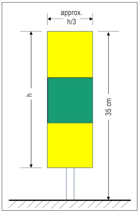
Figure II-5-17. Air taxi-route marker
5.2.12 Helicopter stand marking
5.2.12.1 The helicopter stand markings provide the pilot with a visual indication of:
a) an area that is free of obstacles in which permitted manoeuvring and all necessary ground functions may take place;
b) when required, mass and D-value limitations; and,
c) guidance for manoeuvring and positioning of the helicopter within the stand using TD/PMs.
5.2.12.2 The stand perimeter should be marked: when it is paved, by a yellow line or, when it is unpaved, by flush in-ground markers (see Figure II-5-18). If there is a restriction on the direction of travel, arrows should be provided.
5.2.12.3 Where the stand is designed to accommodate helicopters smaller than the design helicopter, a box containing the limiting D and mass should be displayed on the lead-in line (see Figure II-5-19).
Note.— The limiting mass may not be necessary but is provided to avoid confusion with respect to the units used in the D-value.
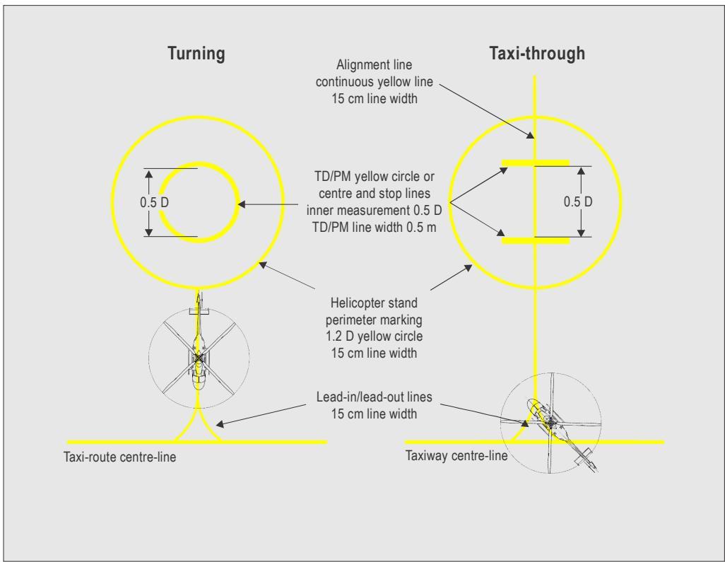
Figure II-5-18. Stand markings
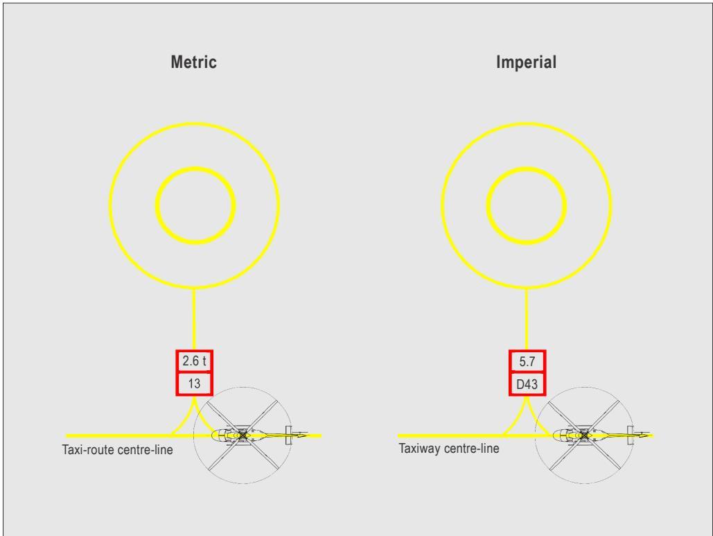
Figure II-5-19. Restricted size stand
5.2.13 Flight-path alignment guidance marking
5.2.13.1 The flight path alignment guidance marking provides the pilot with a visual indication of the available approach and/or departure path direction(s).
5.2.13.2 It should be in a contrasting colour, preferably white, and placed as shown in Figure II-5-21, with the dimensions shown in Figure II-5-20.
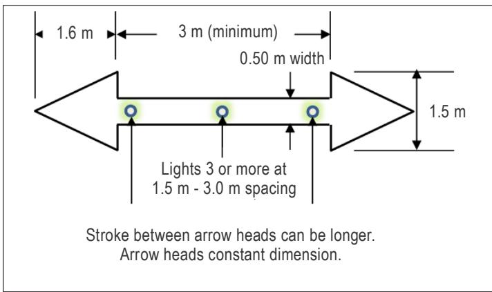
Figure II-5-20. Flight-path alignment guidance marking (dimensions)
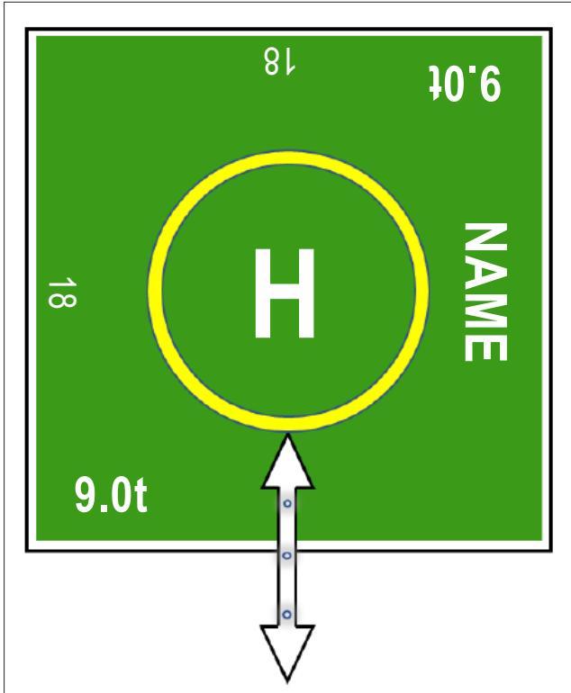
Figure II-5-21. Flight path alignment guidance marking (example)
5.2.14 Obstacle marking
All obstacles should be marked following the specifications in Annex 14, Volume I, Chapter 6.
5.3 LIGHTS
5.3.1 General
5.3.1.1 The guidance contained in this section addresses four issues for operations at night (or in reduced visibility):
a) distinguishing one defined area from another;
b) providing conspicuity for acquiring visual contact with the heliport;
c) providing guidance in the approach and departure phases of flight; and
d) providing visual cues to allow accurate manoeuvring and placement of the helicopter when within the bounds of the heliport.
5.3.1.2 Defined areas may exist in isolation or be collocated or coincidental with each other. The Standards reflect this and although there are provisions for lighting in all defined areas, it is the context of the operation that determines the combination of visual cues required. This is no more evident than in the requirement for lighting in the TLOF, where its location and operational use affect the lighting requirements.
5.3.1.3 The introduction of more powerful helicopters and the subsequent reduction in the size of required surfaces, along with the transfer of functionality from the FATO to the TLOF, has shifted the balance of lighting to the TLOF from the FATO (which can now be in space or not a load-bearing surface). As more elevated heliports and smaller surface level heliports are built, the amount of surface available to accommodate approach lighting systems will be reduced. Fortunately, this has coincided with the improvement of lighting sources, but it has placed the additional function for provision of conspicuity on the TLOF.
5.3.1.4 As the viewing range from the lighting source decreases, the possibility for glare becomes an issue. This is countered through the design of the light by shaping the beam so that intensity decreases with elevation, as seen in Figure II-5-22, illustration 5. With the helicopter on the final stage of the approach, the look-down angle between the pilot and the TLOF will steepen – consequently the light will be viewed outside of the main beam. However, for a category A profile with an extensive vertical element (for some types up to 122 m (400 ft) above the heliport), the lighting still has to provide sufficient visual cues for an OEI landing or a rejected take-off. Calculations using Allard’s Law1 show that, even from 122 m (400 ft), the lighting levels between 20⁰ and 90⁰ provide adequate visual references at extended LDP/TDPs to allow the pilot to touchdown aided by the lit TLOF markings, where provided (see Appendix C to Chapter 5, 1.6).
5.3.1.6 The technical standard for colours of aeronautical ground lights, markings, signs and panels is contained in Annex 14, Volume I, Appendix 1. These standards include filament-type, solid-state lights sources and trans-illuminated panels (arrays of segmented point source lighting (ASPSL) and luminescent panels (LPs). Wherever a colour is referred to in this manual, the specifications in that appendix should apply.
5.3.1.7 The use of ASPSL and LPs in the following sections does not preclude the use of single light source inset lights to illuminate the TD/PM or other markings within the TLOF. However, if inset lights are used, the State should ensure that the intent of Annex 14, Volume 1, Appendix 1 and illustration 6 of Figure II-5-22 are observed, as well as adequate provision of shape information.
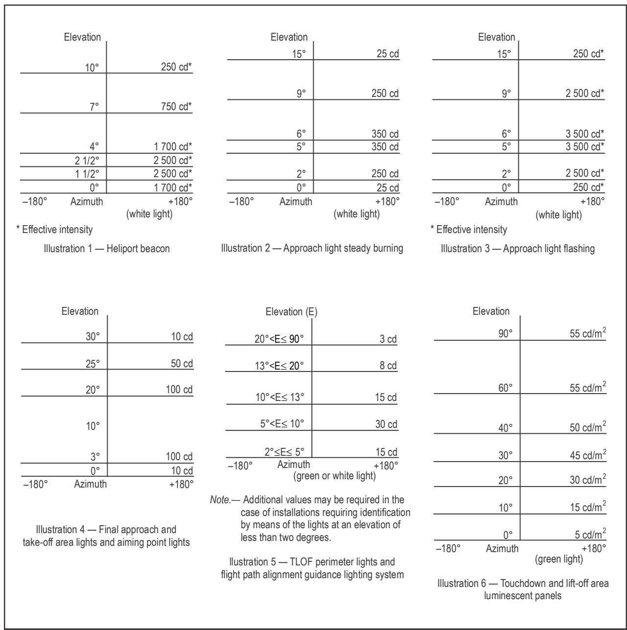
Figure II-5-22. Isocandela diagrams of lights meant for visual heliports
5.3.2 Heliport beacon
5.3.2.1 When long-range visual guidance is necessary and not provided by other visual means, or when identifying the heliport is difficult due to surrounding lights, a heliport beacon should be provided.
5.3.2.2 The heliport beacon should be designed to emit a repeated series of equally spaced short duration white flashes in the format shown in Figure II-5-23. To ensure that pilots are not dazzled during the final stages of the approach and landing, especially at night, brilliancy control (with 10 per cent and 3 per cent settings) or shielding should be provided. The effective light intensity distribution of each flash should be as shown in Figure II-5-22, Illustration 1.
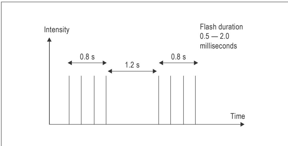
Figure II-5-23. Heliport beacon flash characteristics
5.3.3 Approach lighting system
5.3.3.1 An approach lighting system provides an indication of the preferred approach direction to either enhance the closure rate information to pilots at night or to provide approach guidance for non-precision approaches.
5.3.3.2 Approach lights should be located in a straight line along the preferred direction of approach. The basic system consists of a row of three lights spaced uniformly at 30 m intervals with a crossbar 18 m in length at a distance of 90 m from the perimeter of the final approach and take-off area. The number of lights along the row should be increased to at least seven, extending over a distance of 210 m for non-precision approaches and/or where the identification of the approach lighting system may be difficult.
5.3.3.3 The lights should be omnidirectional steady white lights except that beyond the crossbar either omnidirectional steady or flashing white lights may be used. The light distribution of steady and flashing lights should be as indicated in Figure II-5-22, Illustrations 2 and 3, respectively. However, for a non-precision final approach and take-off area, the intensity of the lights should be increased by a factor of 3. Three different configurations of the approach lighting system are shown in Figure II-5-24.
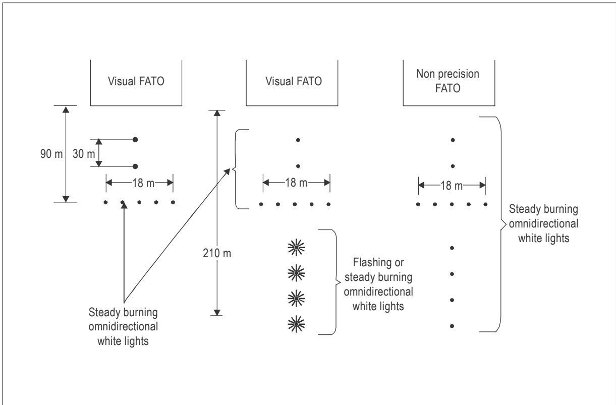
Figure II-5-24. Three different configurations of an approach lighting system
5.3.4 Flight path alignment guidance lighting system
5.3.4.1 Flight path alignment guidance lighting provides the pilot with a visual indication, at night, of the available approach and/or departure path directions. This system should be combined with flight path alignment guidance markings.
5.3.4.2 A flight path alignment guidance lighting system is beneficial in cases where limited amount of surface, on the approach to the FATO and/or TLOF, precludes the use of an approach lighting system (see 5.3.3). It allows flexibility because it may be sited on one or more of the TLOF, FATO, safety area or any suitable surface in the immediate vicinity.
5.3.4.3 The system should consist of a row of three or more lights spaced uniformly a total minimum distance of 6.2 m. Intervals between lights should not be less than 1.5 m and should not exceed 3 m as shown in Figure II-5-20. Where space permits, there should be five lights. The lights should be steady omnidirectional inset white lights. The distribution of the lights should be as indicated in Figure II-5-22, Illustration 5.
5.3.4.4 A suitable control should be incorporated to allow for adjustment of light intensity to meet the prevailing conditions and to balance the flight path alignment guidance lighting system with other heliport lights and general lighting that may be present around the heliport.
5.3.5 Visual alignment guidance system
5.3.5.1 The visual alignment guidance system provides conspicuous and discrete cues to assist a pilot to attain, and maintain, a specified approach track to a heliport when it is impracticable to install an approach lighting system.
5.3.5.2 A visual alignment guidance system should serve the approach to a heliport where one or more of the following conditions exist especially at night:
a) obstacle clearance, noise abatement or traffic control procedures require a particular direction to be flown;
b) the environment of the heliport provides few visual surface cues; and
c) it is physically impractical to install an approach lighting system.
5.3.5.3 For details on visual alignment guidance systems, and a specimen system, see Appendix A to Chapter 5.
5.3.6 Visual approach slope indicator
5.3.6.1 The visual approach slope indicator provides conspicuous and discrete colour cues within a specified elevation and azimuth to assist a pilot to attain, and maintain, the approach-slope necessary to deliver the helicopter to a desired position within a FATO.
5.3.6.2 Standard visual approach slope indicator systems for helicopter operations include, but are not restricted to:
a) precision approach path indicator (PAPI);
b) abbreviated precision approach path indicator (APAPI); or
c) helicopter approach path indicator (HAPI).
5.3.6.3 A visual approach slope indicator system should be provided to serve the approach to a heliport, whether or not the heliport is served by other visual approach aids or by non-visual aids, where one or more of the following conditions exist, especially at night:
a) obstacle clearance, noise abatement or traffic control procedures require a particular slope to be flown;
b) the environment of the heliport provides few visual surface cues; and
c) the characteristics of the helicopter require a stabilized approach.
5.3.6.4 The characteristics of the PAPI and APAPI light units should correspond to those specified in Annex 14, Volume I, except that the angular size of the on-slope sector should be increased to 45 minutes. For further guidance on PAPI and APAPI light units, reference should be made to the Aerodrome Design Manual, Part 4 — Visual Aids (Doc 9157).
5.3.6.5 If required, and when limitations at an elevated heliport preclude the installation of a multi-unit system such as the PAPI or APAPI, a single unit indicator, such as the HAPI, should be installed (the characteristics of the HAPI should correspond to those specified in Appendix B to Chapter 5).
Note.— Other systems meeting the objective of the PAPI, APAPI or HAPI may be approved by the appropriate authority.
5.3.7 FATO lighting systems for surface level heliports
5.3.7.1 The final approach and take-off area lighting system provides to the pilot operating at night an indication of the shape, location and extent of the FATO.
5.3.7.2 Where the FATO has a solid surface, lights should be used to delineate the boundaries of the FATO, unless the extent of the FATO is self-evident or the FATO and TLOF are (or are nearly) coincidental, in which case the TLOF lighting system should be used.
5.3.7.3 The lights should be fixed omnidirectional lights showing white with the intensity and beam spread of the lights as indicated in Figure II-5-22, Illustration 4. Where the intensity of the light varies, it should show variable white. Solid state lights and filament light sources should conform to the chromaticity specifications of Annex 14, Volume 1, Appendix 1, 2.3 e) and 2.1.1 e), respectively.
5.3.7.4 The lights placed along the edge of the FATO should be evenly spaced as follows:
a) for a FATO in the form of a square or rectangle: at intervals of not more than 50 m, with a minimum of four lights on each side including a light at each corner (see Figures II-5-8 and II-5-25); or
b) for a FATO of any other shape: at intervals of not more than 5 m, with a minimum of ten lights.
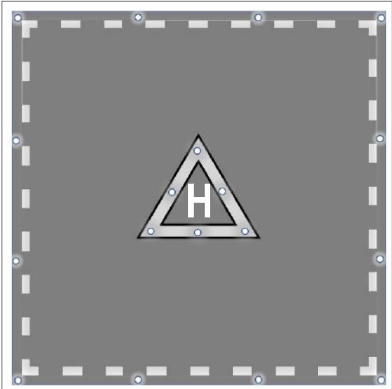
Figure II-5-25. Lighting system for surface level FATO
5.3.8 Aiming point lights
5.3.8.1 Aiming point lights provides a visual cue to the pilot at night indicating the preferred approach/departure direction and, where the FATO is not intended for touchdown, the point to which the helicopter approaches to a hover before positioning to a TLOF, where a touchdown can be made.
5.3.8.2 An aiming point lighting system should consist of evenly spaced omnidirectional white lights as shown in Figure II-5-25 with the intensity and beam spread of the lights of those in Figure II-5-22, Illustration 4. Solid state lights and filament light sources should conform to the chromaticity specifications in Annex 14, Volume 1, Appendix 1, 2.3.1 e) and 2.1.1 e), respectively.
5.3.9 TLOF lighting system
5.3.9.1 General
5.3.9.1.1 The touchdown and lift-off area lighting system provides illumination of the TLOF and required elements within. The necessary elements of the lighting system depend on the siting of the TLOF and its context.
5.3.9.1.2 As well as the TLOF lighting itself, the TLOF may contain elements that are individually illuminated. Examples are:
a) TD/PM; and
b) heliport identification marking (the ‘H’ or cross marking at a hospital).
5.3.9.1.3 For a TLOF in any location, the lighting system should provide sufficient illumination of the surface to enable a pilot, when in close proximity to the TLOF, to identify and use the TD/PM to accurately place the helicopter. This is the basic level of illumination for example, for the TLOF in a stand, where the objective may be met by the use of ambient lighting or apron or stand floodlighting.
5.3.9.1.4 For a TLOF in a FATO, in addition to 5.3.9.1.3, the lighting system should provide sufficient illumination to allow the pilot, when on the final approach, to distinguish the TLOF from other defined areas on the heliport.
5.3.9.1.5 For a TLOF in a FATO on an elevated heliport, the lighting system should, in addition to 5.3.9.1.3 and
5.3.9.1.4 allow:
a) visual acquisition from a range that has been established with respect to the requirements of the heliport; and
b) sufficient shape cues to permit an appropriate approach angle to be established.
Note.— An acceptable approach angle can be established when the TLOF perimeter lighting and/or TDPC illumination are used to provide an indication of the shape of the landing surface. When the approach angle is steep, the TLOF (lighting) will appear in full detail with a round appearance; when shallow, the TLOF (lighting) will appear in little detail as a straight line; when the approach angle is neither steep nor shallow, the TLOF (lighting) will appear to be oval (for illustration purposes, see an example with the illuminated TDPC, Figure II-5-26).
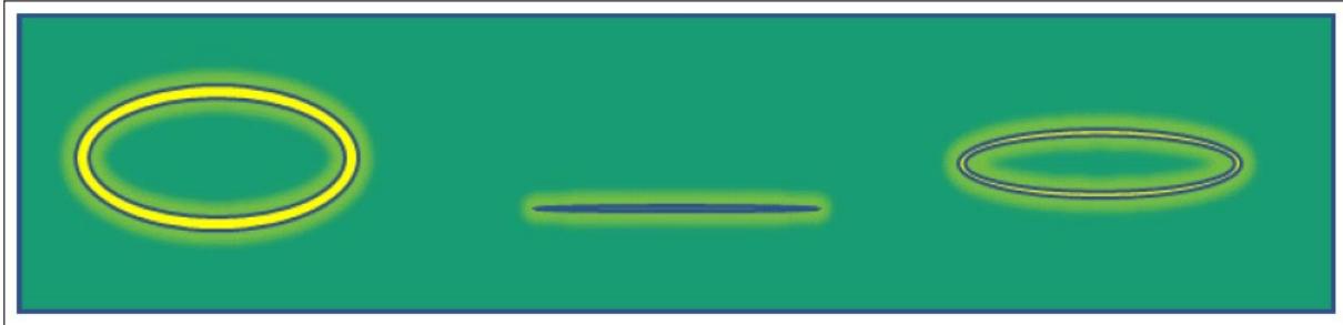
Figure II-5-26. Example of the TDPC as a visual approach cue
5.3.9.1.6 At elevated heliports, surface texture cues within the TLOF are essential for helicopter positioning during the final approach and landing. Such cues can be provided using various forms of lighting (ASPSL, LPs, floodlights or a combination of these lights, etc.) in addition to perimeter lights. Best results have been demonstrated by the combination of perimeter lights and ASPSL in the form of encapsulated strips of light emitting diodes (LEDs) and inset lights to identify the TD/PM and heliport identification markings.
5.3.9.1.7 ASPSL/LPs should have a minimum width of 6 cm and conform to the chromaticity and luminance of Annex 14, Volume I, Appendix 1, 3.4. Unless otherwise specified, the housing cover should be of the same colour as the marking it defines.
5.3.9.1.8 When the ASPSL/LPs are within the TLOF and to avoid a trip hazard, the height of the lighting segments and any associated cabling should be as low as possible and not exceed 25 mm above the surface of the TLOF. The segments should not present any vertical outside edge greater than 6 mm without chamfering at an angle not exceeding 30° from the horizontal. Lighting components, fitments and cabling should be able to withstand a pressure of at least 2,280 kPa (331 lbs/in), without damage. The overall effect of the lighting segments and cabling on deck friction should be minimized.
5.3.9.2 TLOF perimeter lighting
5.3.9.2.1 TLOF perimeter lights should be evenly spaced omnidirectional lights showing green with the intensity and beam spread of the lights of those indicated in Figure II-5-22, Illustration 5. Solid state lights and filament light sources should conform to the chromaticity of Annex 14, Volume I, Appendix 1, 2.3.1 c) and 2.1.1 c), respectively.
5.3.9.2.2 TLOF perimeter light segments: ASPSL/LPs should be evenly spaced and emit green light when they are used to define the boundary of the area. The light distribution should be as shown in Figure II-5-22, Illustration 6.
5.3.9.3 TLOF floodlighting
5.3.9.3.1 Floodlighting, where provided, should be arranged to provide an average horizontal illuminance of at least
10 lux with a uniformity ratio of 8 to 1 (average to minimum) on the surface of the touchdown and lift-off area.
5.3.9.3.2 For many heliports, it may not be possible to achieve the uniformity ratio of 8 to 1 over the entire surface, given the fixture height limitations. Depending upon the distance and angle of projection, the centre portion of the TLOF may have a darkened appearance (the black hole effect). In this circumstance, a combination of floodlighting and ASPSL/LP lighting may prove more effective in providing adequate surface texture cues, including an indication to the pilot of where the helicopter needs to touchdown. This could include, for example, yellow ASPSL/LP lighting of the TDPC. It is essential, therefore, that any floodlighting arrangements take full account of these problems.
5.3.9.3.3 Floodlighting systems, even when properly aligned, can adversely affect the visual cueing environment by reducing the conspicuity of TLOF perimeter lights during the approach and by causing glare during the hover and landing. These undesirable effects are exacerbated when the surface is wet. The lighting should be adequately shielded, e.g. fitted with louvres, to ensure that the source of light is not directly visible to a pilot at any stage of landing.
5.3.9.4 TDPC lighting
5.3.9.4.1 The TDPC lighting should comprise a concentric circle of at least 16 discrete lighting segments situated within 10 cm of the mean radius of the TDPC marking.
5.3.9.4.2 When located on a heliport at a hospital, or at sites where trolley access is required, up to four gaps between 1.5 m and 2.0 m, for a hospital site aligned with the ‘arms’ of the white cross, may be provided to permit access (as shown in Figure II-5-27).
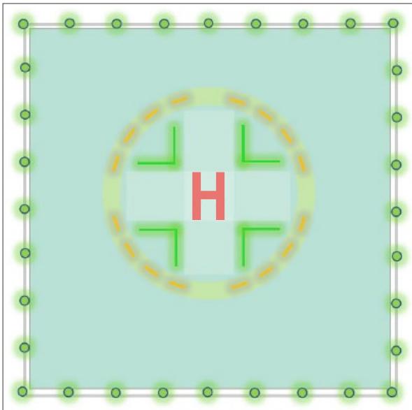
Figure II-5-27. TLOF lighting at an elevated hospital site (with trolley access)
5.3.9.4.3 In the populated circumference (quadrants in the case of a hospital site), the lighting segments should provide coverage of at least 50 per cent and be equidistantly spaced at intervals of not more than 1 m.
5.3.9.5 Heliport identification marking lighting
5.3.9.5.1 The ‘H’ lighting
5.3.9.5.1.1 The ‘H’ should be outlined with green edge lighting consisting of sub-sections between 80 mm and 100 mm wide as shown in Figure II-5-28. The mechanical housing should be coloured white.
5.3.9.5.1.2 If a sub-section is made up of individual lighting elements (e.g. LED’s), they should be of nominally identical performance (i.e. within manufacturing tolerances) and be equidistantly spaced within the sub-section to aid textural cueing. Minimum spacing between the illuminated areas of the lighting elements should be 3 cm and maximum spacing 10 cm.
5.3.9.5.1.3 If the sub-section comprises a continuous lighting element (e.g. fibre optic cable, electro luminescent panel), to achieve textural cueing at short range, the element should be masked at 3.0 cm intervals on a 1:1 mark-space ratio.
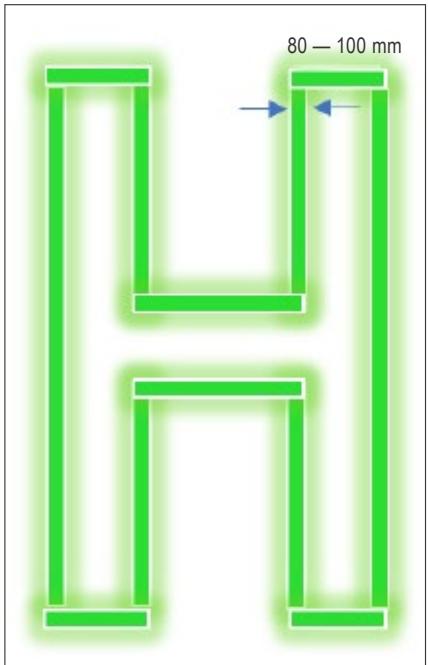
Figure II-5-28. ‘H’ lighting
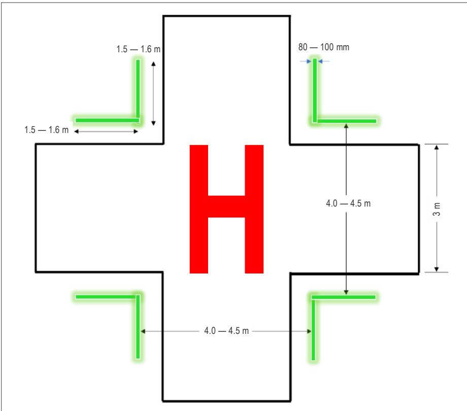
Figure II-5-29. Heliport cross lighting
5.3.9.5.2 Cross lighting at a hospital heliport
5.3.9.5.2.1 The white cross marking should be lit using green right-angled lit chevron markings located adjacent to each of the four internal corners of the 9 m x 9 m white cross. Each chevron should be 1.5 m to 1.6 m x 1.5 m to 1.6 m in size and be spaced by 4.0 m to 4.5 m as shown in Figure II-5-29.
5.3.9.5.2.2 The cross marking should comprise sub-sections of between 80 mm and 100 mm wide. Where applicable, the gaps between them should not be greater than 10 cm. The mechanical housing should be coloured white.
Note.— A specimen lighting scheme designed for a hospital heliport that employs a number of the enhancements described above is contained in Appendix C to Chapter 5.
5.3.9.6 The TLOF in a surface level FATO
5.3.9.6.1 This lighting system should consist of one or more of the following:
a) perimeter lighting;
b) floodlighting (see Figure II-5-30); or
c) ASPSLs or LPs (on their own only when FATO lights are available as shown in see Figure II-5-31).
5.3.9.6.2 ASPSL/LPs to identify the TD/PM, heliport identification marking and/or floodlighting should be provided for heliports intended for use at night when enhanced surface texture cues are required.
Figure II-5-30. Surface level FATO and TLOF with floodlighting
Figure II-5-31. Surface level FATO with perimeter and TDPC lighting
5.3.9.6.3 Perimeter lights
5.3.9.6.3.1 Perimeter lights should be placed along the boundary of the TLOF or within a distance of 1.5 m from the edge and uniformly spaced at intervals of not more than 5 m.
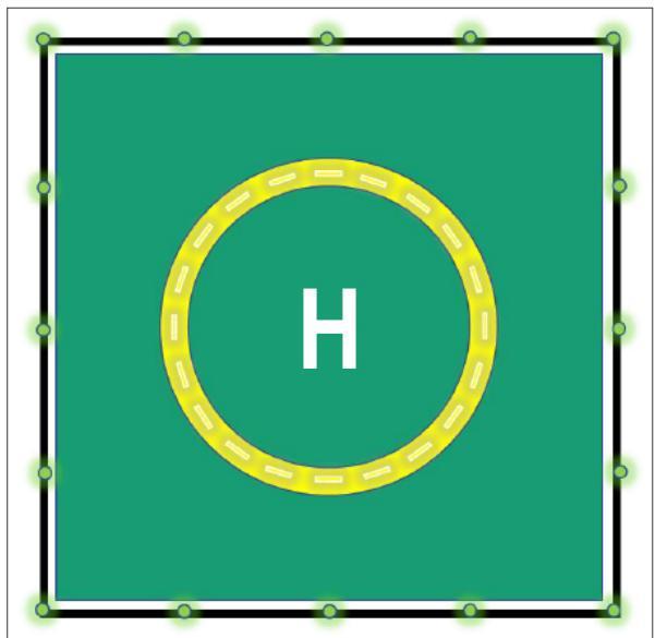
Figure II-5-32. Surface level heliport perimeter and TDPC lighting (Square TLOF)
5.3.9.6.3.2 Where the TLOF is rectangular or square, there should be a minimum of four lights on each side including a light at each corner; this will result in a minimum of twelve lights (Figure II-5-32 shows a TLOF of 20 m which, because of minimum spacing requirements, has five lights on each side).
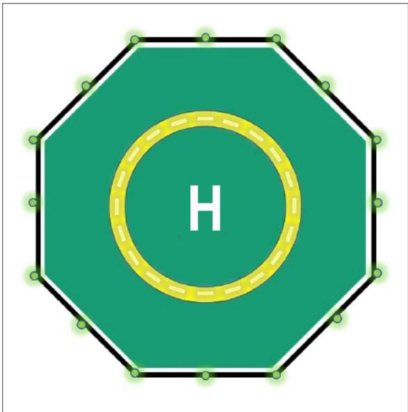
Figure II-5-33. Surface level heliport perimeter and TDPC lighting (Octagonal TLOF)
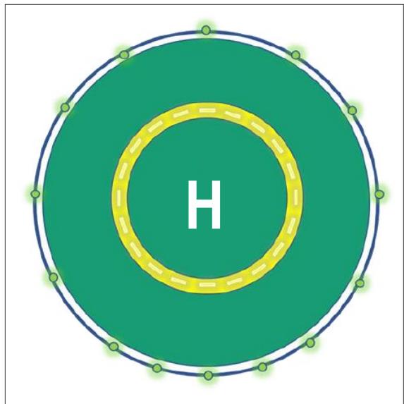
Figure II-5-34. Surface level heliport perimeter and TDPC lighting (Circular TLOF)
5.3.9.6.3.3 Where the TLOF has more than four sides, there should be a minimum of three lights on each side including a light at each corner; this will result, for an octagonal TLOF, in sixteen lights as shown in Figure II-5-33.
5.3.9.6.3.4 Where the TLOF is circular, the perimeter lights should be located on straight lines in a pattern which will provide information to pilots on drift displacement. Where it is not practicable to so locate the lights, they should be evenly spaced around the perimeter of the area at the appropriate interval except that over a sector of 45° the lights should be placed at half spacing as in Figure II-5-34 (where flight path alignment guidance lighting is provided, additional lights should not be necessary). There should be a minimum of fourteen lights.
5.3.9.6.3.5 Perimeter lights should be fixed omnidirectional lights showing green. The light distribution of perimeter lights should conform to that specified in Figure II-5-22, Illustration 5.
5.3.9.6.4 Perimeter light segments
5.3.9.6.4.1 ASPSL/LPs should be placed along the marking designating the edge of the TLOF and be equally spaced with a distance between adjacent panel ends of not more than 5 m. The total length of ASPSL/LPs in a pattern should not be less than 50 per cent of the length of the pattern.
5.3.9.6.4.2 Where the TLOF is a rectangle or square, there should be a minimum of three ASPSL/LPs on each side of the TLOF with one at each corner as in Figure II-5-35.
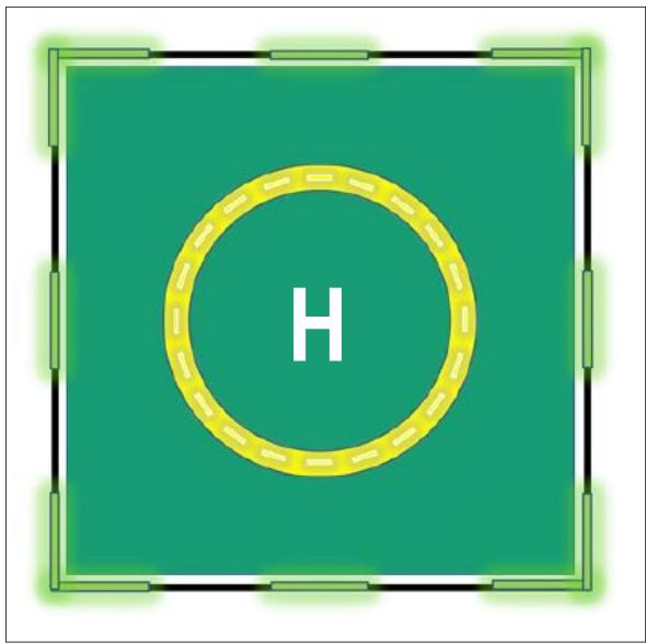
Figure II-5-35. Surface level heliport ASPSL/LPs (Square TLOF)
5.3.9.6.4.3 Where the TLOF is a circle, the panels should be located on straight lines circumscribing the area as in Figure II-5-36. There should be a minimum of nine ASPSL/LPs.
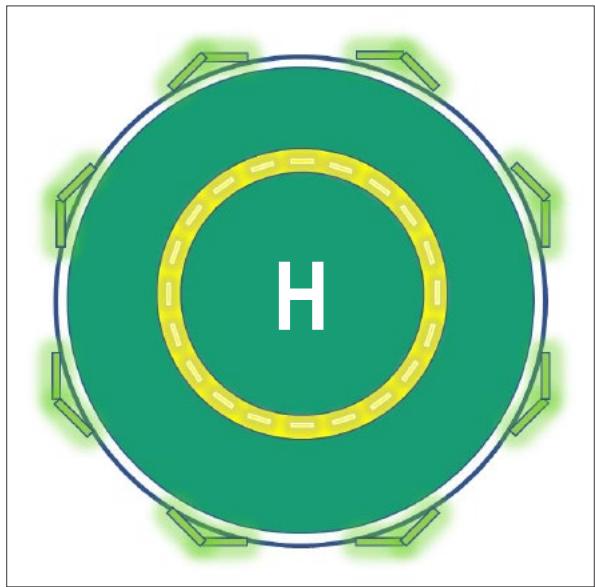
Figure II-5-36. Surface level heliport ASPSL/LPs (Circular TLOF)
5.3.9.6.4.4 ASPSL/LPs should emit green light when they are used to define the boundary of the area and the light distribution should be as shown in Figure II-5-22, Illustration 6.
5.3.9.6.5. Enhanced texture cue lighting
5.3.9.6.5.1 Floodlights should be located so as to avoid glare to pilots at the final stages of approach and landing, and the arrangement and aiming of the lights should be such that shadows are kept to a minimum.
5.3.9.6.5.2 The TD/PM and/or the heliport identification marking should be provided in accordance with 5.3.9.4 and
5.3.9.5.
5.3.9.7 The TLOF on an elevated heliport FATO
5.3.9.7.1 The touchdown and lift-off area lighting system at an elevated heliport provides visual acquisition from a defined range and sufficient shape cues to permit an appropriate approach angle to be established.
5.3.9.7.2 The lighting should consist of:
a) perimeter lights; and
-
ASPL/LPs, to identify the TD/PM; or
-
floodlighting, to illuminate the TLOF.
Note.— Perimeter light segments may not be suitable for elevated heliports because of limited conspicuity compared to perimeter lights.
5.3.9.7.3 Perimeter lights should be as specified in 5.3.9.6.3, except that they should be installed at a spacing of not more than 3 m (see Figure II-5-37).
5.3.9.7.4 ASPSL/LPs or floodlighting should be provided at elevated heliports to offer surface texture cues within the touchdown and lift-off area. These cues are essential to ensure accuracy of positioning for the helicopter during the final approach and hover to landing.
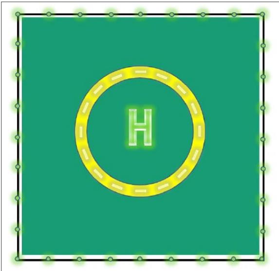
Figure II-5-37. Elevated heliport perimeter, heliport identification and TDPC lighting
5.3.9.7.5 When ASPSL/LPs are used on an elevated heliport to enhance the surface texture cues, they should not be placed adjacent to the perimeter lights. Suitable locations include around a touchdown positioning marking circle or coincident with the heliport identification “H” marking or cross marking (see Figure II-5-37).
5.3.10 Helicopter stand lighting
5.3.10.1 The helicopter stand lighting provides illumination of the stand surface and associated markings, assists the manoeuvring and positioning of a helicopter, and allows essential operations around the helicopter to be conducted safely.
5.3.10.2 This may be achieved with apron floodlighting or ambient lighting. Guidance on apron floodlighting is given in the apron floodlighting section in the Aerodrome Design Manual, Part 4 — Visual Aids (Doc 9157).
5.3.10.3 Helicopter stand floodlights should provide adequate illumination, with a minimum of glare to the pilot of a helicopter in flight and on the ground, and to personnel on the stand. Floodlights should be arranged and aimed such that a helicopter stand receives light from two or more directions to minimize shadows
5.3.10.4 The spectral distribution of stand floodlights should be such that the colours used for surface and obstacle marking can be correctly identified.
5.3.10.5 Horizontal and vertical illuminance should be sufficient to ensure that visual cues are discernible for required manoeuvring and positioning, and essential operations around the helicopter can be performed expeditiously without endangering personnel or equipment.
5.3.11 Helicopter taxiway/air taxi-route lighting
5.3.11.1 The taxiway/air taxi-route lighting provides illumination of the markings or markers.
5.3.11.2 Helicopter taxiways should be lighted in the same manner as a taxiway meant for use by aeroplanes (see Annex 14, Volume I, Chapter 5).
5.2.11.3 When not collocated with a taxiway, air taxi-route markings should be lighted as for taxiways; air taxi-route markers should be internally illuminated or rendered retro-reflective.
5.3.12 Obstacle marking and lighting
5.3.12.1 Obstacle lighting
5.3.12.1.1 An obstacle at a heliport should be lit in the same manner as at an airport as per the specifications in Annex 14, Volume I, Chapter 6.
5.3.12.1.2 Where a heliport is isolated or rarely used and to avoid unnecessary light pollution, obstacle lighting may be activated at the time of use.
5.3.12.2 Obstacle floodlighting
It is preferable for some structures, such as trees and towers, to be illuminated by floodlights as an alternative to fitting intermediate steady red lights, provided that the lights are arranged such that they adequately illuminate the structure and do not dazzle the helicopter pilot.
Appendix A to Chapter 5
VISUAL ALIGNMENT GUIDANCE SYSTEM
1. GENERAL
1.1 The visual alignment guidance system first introduced in Chapter 5, 5.3.5 is designed to give visual indications of the correct track. This system is mainly recommended to serve the approach to a heliport where one or more of the following conditions exist, especially at night:
a) when obstacle clearance, noise abatement or traffic control procedures require a particular direction to be flown;
b) where the environment of the heliport provides few visual surface cues; and
c) when it is physically impractical to install an approach lighting system.
1.2 The system provides a minimum of three discrete signal sectors giving “offset to the right”, “on track” and “offset to the left” indications.
Note.— When installed and used in the prescribed manner, a visual alignment guidance system will provide a safe lateral clearance from obstacles when on final approach.
1.3 The material in this chapter provides guidance in the application of Chapter 5, 5.3.5, considering that visual alignment guidance systems:
a) of different designs may be in use; and
b) may be installed on heliports with widely varying physical characteristics.
2. TYPE OF SIGNAL
2.1 The signal of the visual alignment guidance system should be such that there is no possibility of confusion between the system, and any associated visual approach slope indicator or other visual aids.
2.2 The system should avoid the use of the same coding as any associated visual approach slope indicator.
2.3 The use of the system should not significantly increase the pilot workload and the signal format should be unique and conspicuous in all operational environments for which it is intended to use the visual alignment guidance system.
3. LAYOUT AND SETTING ANGLE
3.1 The visual alignment guidance system should be located such that a helicopter is guided along the prescribed track towards the final approach and take-off area, and should be placed at its downwind edge and aligned along the preferred approach direction.
3.2 The system should be capable of adjustment in azimuth to within ±5 minutes of arc of the desired approach track.
3.3 Where the lights of the system need to be seen as discrete sources, light units should be located such that at the extremes of the system coverage the angle subtended between units as seen by the pilot should not be less than 3 minutes of arc. The angle subtended between light units of the system and other lights of comparable or greater intensity should also not be less than 3 minutes of arc. This can be met for lights on a line normal to the line of sight if they are separated by 1 m for every kilometre of viewing range.
3.4 The divergence of the “on track” sector of the system should be 1° on either side of the centreline (see Figure II-5-A-1).
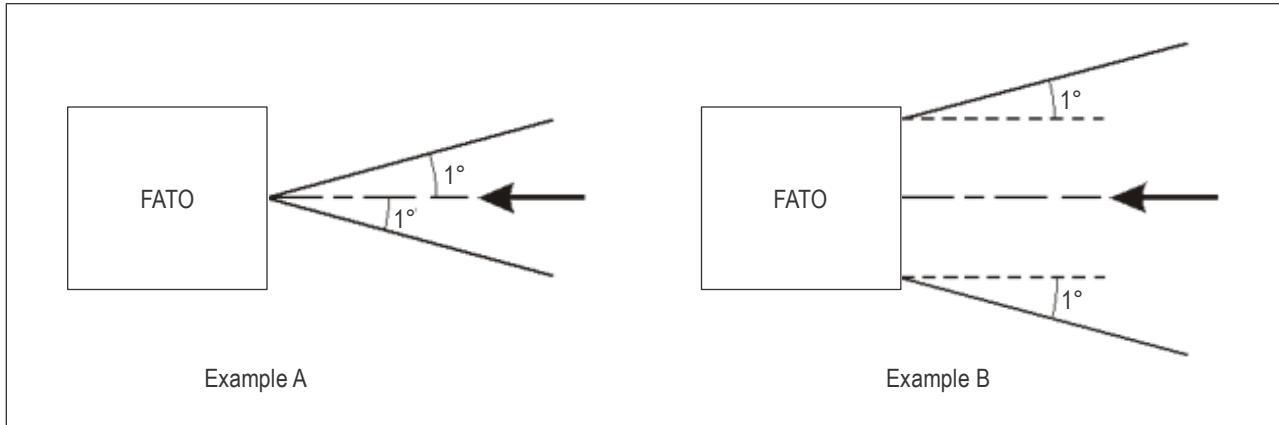
Figure II-5-A-1. Divergence of the “on track” sector
4. BRILLIANCY
A suitable intensity control should be provided so as to allow adjustment to meet the prevailing conditions and to avoid dazzling the pilot during approach and landing. When the system is used in conjunction with a visual approach slope indicator, the intensity settings should be compatible.
5. CHARACTERISTICS
5.1 In the event of the failure of any component affecting the signal format, the system should be automatically switched off. The characteristics of the obstacle protection surfaces specified for PAPI, APAPI and HAPI systems should apply equally to the visual alignment guidance system (see Figure II-5-B-4).
5.2 The light units should be so designed that deposits of condensation, ice, dirt, etc., on optically transmitting or reflecting surfaces can be removed to ensure they will not interfere with the light signal and will not cause spurious or false signals to be generated.
6. INITIAL FLIGHT INSPECTION
A flight inspection of a new installation is recommended to confirm the correct operation of the system. The inspection should include checks of the divergence of the “on track” sector, azimuth and vertical coverage, range, brilliancy control and compatibility with the approach slope indicator.
7. ROUTINE INSPECTION
7.1 The initial setting will be accomplished either by the manufacturer’s agent or under strict compliance with the manufacturer’s installation instructions. Thereafter, a suitable routine inspection schedule should be established to ensure that the system remains operationally safe.
7.2 A routine check should be made on the visual alignment guidance system to ensure that:
a) all lamps are lighted and illuminated evenly;
b) no evidence of damage is apparent;
c) the signal format is correct;
d) the optically transmitting or reflecting surfaces are not contaminated; and
e) the control systems are operating properly.
8. OBSTACLE CONSIDERATIONS
The angle of azimuthal setting of the system should be such that during an approach, the pilot of a helicopter at the boundary of the “on track” signal will clear all objects in the approach area by a safe margin. The characteristics of the obstacle protection surface specified in Appendix B to Chapter 5, 1.15.2, Table II-5-B-2 and Figure II-5-A-2 for visual approach indicators should equally apply to the system.
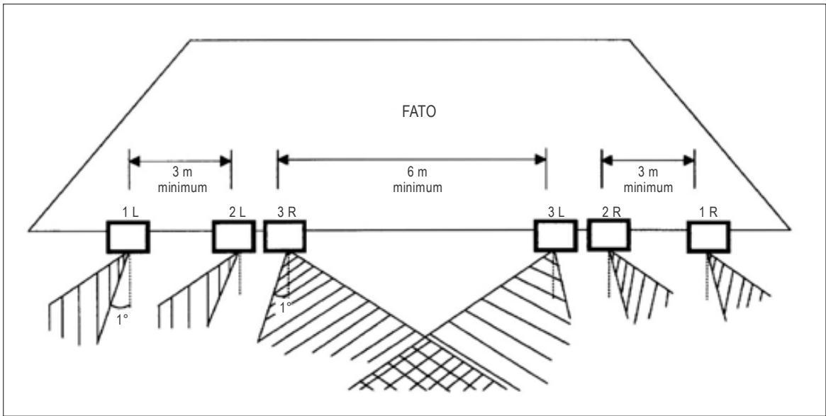
Figure II-5-A-2 Siting of the alignment guidance system
9. EXAMPLE OF AN ALIGNMENT GUIDANCE SYSTEM
9.1 Description. An example of a visual alignment guidance system is illustrated in Figure II-5-A-2. The system consists of six pulsing units arranged in two groups of three units, each as indicated in Figure II-5-A-2. One group is located on the left side of the approach track and the other group on the right side. The system works as follows:
a) when on the correct approach track, the pilot will see the two light units designated as 3R and 3L simultaneously flashing like a runway threshold identification light as specified in Annex 14, Volume I, Section 5.3.9; and
b) when to the left or right of the correct approach track, the pilot will see three lights flashing one after another indicating the direction of correction, for example, 1L, 2L, 3L if the pilot is to the left of the correct approach track.
9.2 Location. The system should preferably be located on the downwind edge of the final approach and take-off area as shown in Figure II-5-A-2. The separation distances between the light units should be as shown in that figure. Where a HAPI is used in conjunction with the visual alignment guidance system, the HAPI should be sited behind the alignment guidance system and at the centre of units 3R and 3L. A spacing of 4 to 5 m between light units 3R and 3L might prove to be adequate where a HAPI is collocated with the system. Where sufficient room is available, the HAPI may be installed aligned with the units of the system and at the centre of units 3R and 3L.
9.3 Signal format. The signal format of the visual alignment guidance system includes three discrete signal sectors providing “offset to the left”, “on track” and “offset to the right” signals as shown below. The “offset sector” flash characteristics are shown in Figure II-5-A-3 and Table II-5-A-1. The system also includes two additional narrow sectors providing “slightly offset” signals. In these “slightly offset” sectors, the system shows two white lights flashing in sequence, still indicating the direction of correction.
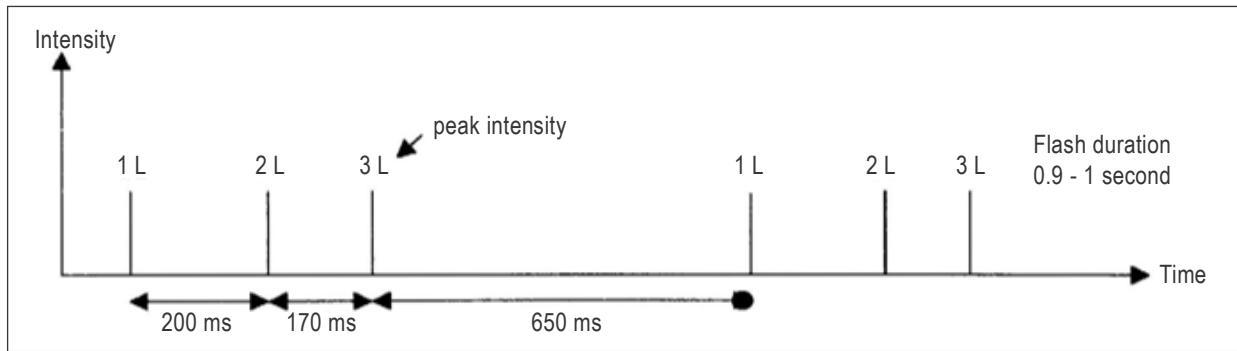
Figure II-5-A-3. Offset touchdown marking
9.4 Setting of the system. The divergence of the “on track” sector of the system should be set at 1° as shown in Figure II-5-A-1. The system is generally housed in a casing similar to that used for PAPI.
9.5 Light distribution. The system should have the same coverage as envisaged in the Heliport Manual, for a visual slope indicator system meant for helicopter operations. This would ensure that a pilot will not lose the signals of either system when they are used in conjunction. The light units have a peak intensity of 15 000 cd.
9.6 The system provides intensity settings of 100 per cent, 30 per cent and 10 per cent capable of being remotely controlled by the pilot from the helicopter.
Table II-5-A-1. Visual Alignment Guidance System (Light coding)
| Sector | Offset to the left | On track | Offset to the right |
| Signal | Three white lights flashing in sequence from left to right | Two white lights flashing together (3R and 3L) | Three white lights fl ashing in sequence from right to left (1R, 2R and 3R) |
Appendix B to Chapter 5
HELICOPTER APPROACH PATH INDICATOR
1. GENERAL
1.1 The HAPI defined in Chapter 5, 5.3.6, is designed to give visual indications of the desired approach slope and any vertical deviation from it.
1.2 A HAPI should be located such that a helicopter is guided to the desired position within the FATO so as to avoid dazzling the pilot during final approach and landing. This will usually entail the HAPI being located adjacent to the nominal aiming point and aligned in azimuth with the preferred approach direction.
1.3 HAPI is a single unit device providing one normal approach path and three discrete deviation indications.
Note.— The helicopter (visual) approach path indicator system is closely associated with the safety of helicopter operations. It is considered desirable to remind users of this manual that the system, when installed and used in the prescribed manner, will provide a safe margin, clear of all obstacles when on final approach. HAPIs may be installed on heliports with widely varying physical characteristics.
2. TYPE OF SIGNAL
2.1 The signal format of the HAPI should include four discrete signal sectors, providing an above slope, an on slope, a slightly below slope and a below slope signal.
2.2 HAPI is a projector unit producing a light signal, the lower half of which is red and the upper half of which is green. An occulting device creates at the top of the green signal, and at the bottom of the red signal, a flashing effect as shown at Figure II-5-B-1.
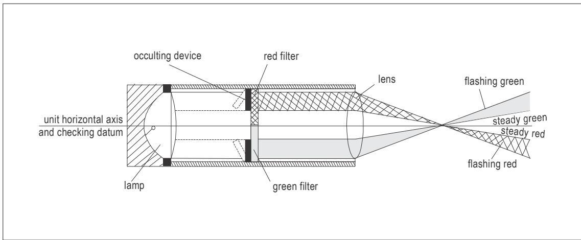
Figure II-5-B-1. HAPI light unit
2.3 The signal repetition rate of the flashing sector should be at least 2 Hz. The on to off ratio of pulsing signals should be 1 to 1 and the modulation depth at least 80 per cent. The angular size of the on slope sector should be 45 minutes and the angular size of the slightly below sector should be 15 minutes.
2.4 The angle of elevation setting of HAPI should be such that during an approach the pilot of a helicopter observing the upper boundary of the below slope signal will clear all objects in the approach area by a safe margin.
2.5 The light distribution of the HAPI in red and green colours should be as shown in Figure II-5-22, Illustration 4. The transmittance of a red or green filter should be greater than 85 per cent at the maximum intensity setting. At full intensity the red light should have a Y coordinate not exceeding 0.320 and the green light should be within the boundary specified for Annex 14, Volume I, Appendix 1, 2.3.1 (c).
Note.— Care should be taken in the design to minimize spurious signals between the signal sectors and the azimuth coverage limits. A larger azimuth coverage may be obtained by installing the HAPI system on a turntable.
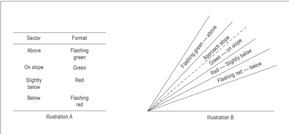
Figure II-5-B-2. HAPI signal format
3. EQUIPMENT SPECIFICATIONS
3.1 The colour transition between the adjacent sectors of the signal in the vertical plane should appear to an observer at a distance of not less than 300 m to occur within a vertical angle of not more than 3 minutes.
3.2 The occulting device should be so designed that, in case of failure, no light will be emitted in the failed flashing sector.
4. SETTING ANGLES
4.1 During manufacture, the centre of the plane of transition between the steady-red and green signals should be aligned precisely with the unit’s horizontal axis (Figure II-5-B-2, HAPI light unit). The unit setting angle and the centre of the on-course sector are not the same. Thus, the setting angle should be related to the red-green boundary (see Section 13).
4.2 A HAPI system should be capable of adjustment in elevation to any desired angle between 1° and $1 2 ^ { \circ }$ above the horizontal, with an accuracy of ±5 minutes of arc.
4.3 The HAPI units should be so designed that in the event of a vertical misalignment exceeding $\pm 0 . 5 ^ { \circ }$ , the system will switch off automatically. If the flashing mechanism fails, no light will be omitted in the failed flashing sectors.
5. BRILLIANCY
A suitable intensity control should be provided to allow adjustment to meet the prevailing conditions and to avoid dazzling the pilot during approach and landing.
6. MOUNTING
6.1 Firm bases are essential for HAPI units as for any precision system. The design of the mounting should, therefore, be such as to provide maximum stability.
6.2 The HAPI system should be mounted and sited as low as possible so as not to constitute a hazard to helicopters.
7. BLAST RESISTANCE
The HAPI system should maintain its setting angle when exposed to rotor downwash and environmental conditions.
8. RESISTANCE TO FOREIGN MATTER
8.1 The HAPI should be designed as a sealed unit to prevent the ingress of foreign matter and formation of salt deposits on the lens systems.
8.2 The unit should be constructed of materials resistant to corrosion.
9. CONDENSATION AND ICE
Low-power heater elements (50 to 100 W) may be needed to prevent the formation of condensation and ice on optically transmitting or reflecting surfaces, i.e. lenses of light units. Operation of light units at a lower power setting (20 W per lamp), when the unit is not in use, has also been shown to be a satisfactory method of prevention. Units which do not have some means of keeping the lens glasses warm need an adequate, full-intensity warm-up period before use to disperse condensation or remove ice from the lenses. The appropriate warm-up time for a HAPI unit should be established.
10. INITIAL FLIGHT INSPECTION
A flight inspection of a new installation is recommended to confirm the correct operation of the system. The inspection should include checks of the azimuth coverage, range, setting angle, brilliancy control and compatibility with the ILS or MLS (if provided).
11. Routine inspection
11.1 The initial setting-up will be accomplished either by the manufacturer’s agent or under strict compliance with the manufacturer’s installation instructions. Thereafter, a suitable routine inspection schedule should be established to ensure that the system remains operationally safe.
11.2 A regular check should be made on HAPI systems to ensure that:
a) all lamps are lighted and illuminated evenly;
b) no evidence of damage is apparent;
c) the signal format is correct;
d) the change of signals is coincident for all optical elements in a HAPI unit;
e) the lenses are not contaminated; and
f) the control systems are operating properly.
12. METHOD OF CHECKING
The setting angle is checked using a clinometer or an equivalent means set to the appropriate angle and placed on the checking datum. Errors in excess of 3 minutes of arc should be corrected.
13. LAYOUT AND ELEVATION SETTING ANGLE
13.1 The HAPI unit should be located as to avoid dazzling pilots at the final stages of the approach and landing. The minimum setting angle of HAPI is 1°. On a surface-level heliport or on an elevated heliport, HAPI should preferably be installed either on the left or on the right side of the final approach and take-off area. It can, at times, be desirable to have it on the axis of the preferred approach. In those cases, the HAPI unit should be placed on the centre of the inner edge of the final approach and take-off area.
13.2 When placed on a turntable, on an elevated heliport the HAPI system can be aligned to the desired approach axis.
13.3 Examples of HAPI with three difference settings are illustrated in Figure II-5-B-3.
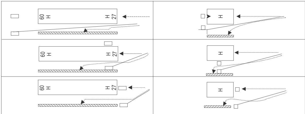
Figure II-5-B-3. HAPI with three difference settings
14. CLEARANCE FROM FATO
The HAPI unit should not penetrate any obstacle limitation surface.
15. OBSTACLE CONSIDERATIONS
15.1 An obstacle protection surface should be established when it is intended to provide a visual approach slope indicator system. The characteristics of this surface i.e. origin, divergence, length and slope should correspond to those in the relevant column of Table II-5-B-2 and Figure II-5-B-4. New objects or extensions of existing objects should not be permitted above an obstacle protection surface except when, in the opinion of the appropriate authority, the new object or extension would be shielded by an existing immovable object. Guidance is provided in the Airport Services Manual, Part 6 — Control of Obstacles (Doc 9137).
Table II-5-B-2. Dimensions of the obstacle protection surface
| Surface and dimensions | FATO |
| Length of inner edge | Width of safety area |
| Distance from end of FATO | 3 m minimum |
| Divergence | 10 per cent |
| Total length | 2 500 m |
15.2 Existing objects above an obstacle protection surface should be removed except when, according to the appropriate authority, the object is shielded by an existing immoveable object, or following an aeronautical study it is determined that the object will not adversely affect the safety of helicopter operations. In cases where an existing object could adversely affect the safety of helicopter operations, one or more of the following measures should be taken:
a) suitably raise the approach slope of the system;
b) reduce the azimuth spread of the system so that the object is outside the confines of the beam;
c) displace the axis of the system and its associated obstacle protection surface by no more than 5 degrees; and/or
d) suitably displace the FATO and install a visual alignment guidance system.
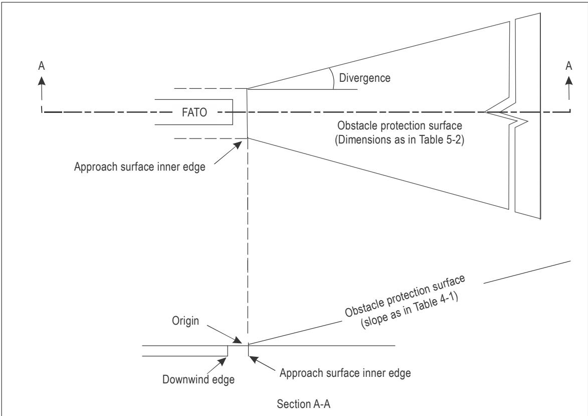
Note: the HAPI should be located with the confines of the dotted lines either side of the FATO unless the width of the ‘obstacle protection surface’ is adjusted accordingly.
Figure II-5-B-4. Obstacle protection surface
15.3 The location and approach angle of HAPI may be influenced by the presence of obstacles in the approach area. The area to be surveyed is shown in Table II-5-B-2 and Figure II-5-B-4.
15.4 Table II-5-B-2 shows the dimensions and divergences of the obstacle protection surface for the three types of visual approach slope indicators meant for use at heliports. These surfaces are derived from the approach surfaces specified in Annex 14, Volume II, Chapter 4 and Appendix 2.
15.3 The azimuth spread of the light beam should be suitably restricted where an object located outside the obstacle protection surface of the HAPI system, but within the lateral limits of its light beam, is found to extend above the plane of the obstacle protection surface, and an aeronautical study indicates that the object could adversely affect the safety of operations. The extent of the restriction should be such that the object remains outside the confines of the light beam.
Appendix C to Chapter 5
EXAMPLE OF THE UNITED KINGDOM SPECIFICATIONFOR A HOSPITAL HELIPORT LIGHTING SYSTEM
1. OVERALL OPERATIONAL REQUIREMENT
1.1 The whole lighting configuration should be visible over a range of 360° in azimuth.
1.2 The visibility of the lighting configuration should be compatible with operations in a meteorological visibility of 3 000 m.
1.3 The lighting configuration aids the helicopter pilot perform the necessary visual tasks during approach and landing as detailed in Table II-5-C-1.
Table II-5-C-1. Visual tasks during approach and landing
| Phase ofapproach | Visual task | Visual cues/ aids | Desired range (NM) |
| 3 000 m met. vis. | |||
| Heliport locationand identification | Search for heliport within thehospital complex. | Shape of heliport,colour of heliport,luminance of heliport,perimeter lighting. | 1.1(2 km) |
| Final approach | Detect helicopter position inthree axes.Detect rate of change ofposition. | Apparent size/shape andchange of size/shape ofheliport.Orientation and change oforientation of known features/markings/lights. | 0.75(1.4 km) |
| Hover andlanding | Detect helicopter attitude,position and rate of change ofposition in three axes (sixdegrees of freedom). | Known features/ markings/lights.Heliport texture. | 0.03(50 m) |
1.4 The minimum intensities of the lighting configuration should be adequate to ensure that, for a minimum meteorological visibility (met. vis.) of 3 000 m and an illuminance threshold of 10-6.1 lux, each feature of the system is visible and useable at night from ranges as follows:
a) perimeter lights are to be visible and usable at night from a minimum range of 1.1 NM;
b) TDPC on the heliport is to be visible and usable at night from a range of 0.75 NM; and
c) cross marking is to be visible and usable at night from a range of 0.375 NM.
1.5 The design of the perimeter lights, TDPC and cross marking should be such that the luminance of the perimeter lights is equal to or greater than that of the TDPC segments, and the luminance of the TDPC segments equal to or greater than that of the cross marking.
1.6 Some onshore operations at heliports with difficult obstacle environments have access to Category A procedures with vertical components of up to 122 m (400 ft). This extensive vertical component places the helicopter in the 20⁰ to 90⁰ sector where the minimum lighting intensities for the components are as follows:
Table II-5-C-2. Lighting intensity
| Component | Minimum intensity (cd)for elevationsfrom 20°to 90° | Comments |
| Perimeter lights | 3.0 | See Table Il-5-C-4 |
| TDPC | 0.375 | 0.5 m segment - see Table ll-5-C-5and Figure ll-5-C-2 |
| Cross marker | 0.1 | 1.5 m limb - see Table ll-5-C-6 |
1.7 Assuming an eye illuminance threshold = -6.0 log lux (see Annex 3 — Meteorological Service for International Air Navigation, Attachment D) and a minimum meteorological visibility of 3 000 m, Allard’s Law predicts the following maximum ranges
Table II-5-C-3. Conspicuity ranges
| Component | Range (m) | |
| Detectable | Conspicuous* | |
| Perimeter lights | 1034 | 690 |
| TDPC | 481 | 297 |
| Cross marker | 278 | 164 |
| *It is common practice to increase the required intensity by half in order (i.e. multiply by √10) toensure that the light source is conspicuous rather than just detectable. In this case, the minimumintensities are divided by V10 to calculate the reduced range for conspicuity. | ||
1.8 For the worst case, the maximum range at which the component (cross marker limb) will be conspicuous is
162 m (533 ft), easily encompassing the height of Category A procedures.
2. DEFINITIONS
2.1 Lighting element. A lighting element is a light source within a segment or sub-section and may be discrete (e.g. LED) or continuous (e.g. fibre optic cable, electro luminescent panel). An individual lighting element may consist of a single light source or multiple light sources arranged in a group or cluster and may include a lens/diffuser.
2.2 Segment. A segment is a section of the TDPC lighting. For the purposes of this specification, the dimensions of a segment are the length and width of the smallest possible rectangular area that is defined by the outer edges of the lighting elements, including any lenses/diffusers.
2.3 Sub-section. A sub-section is an individual section of the cross marking lighting. For the purposes of this specification, the dimensions of a sub-section are the length and width of the smallest possible rectangular area that is defined by the outer edges of the lighting elements, including any lenses/diffusers.
3. THE PERIMETER LIGHT REQUIREMENT
3.1 Configuration. Perimeter lights spaced at intervals no more than 3 m should be fitted around the perimeter of the landing area of the heliport as described in Chapter 5, Section 2.
3.2 Mechanical constraints. The perimeter lights should not exceed a height of 25 cm above the surface of the heliport.
3.3 Light intensity. The minimum light intensity profile is given in Table II-5-C-4. No perimeter light should have an intensity of greater than 60 cd at any angle of elevation. Note that the design of the perimeter lights should be such that the luminance of the perimeter lights is equal to or greater than that of the TDPC segments.
Table II-5-C-4. Minimum light intensity profile for perimeter lights
| Elevation | Azimuth | Intensity (min) |
| 0^to 10°$ | $- 1 8 0 ^ { \circ } \ t \circ + 1 8 0 ^ { \circ }$ | 30 cd |
| ${ > } 1 0 ^ { \circ } \ \mathrm { t o } \ 2 0 ^ { \circ }$ | $- 1 8 0 ^ { \circ } \ t \circ + 1 8 0 ^ { \circ }$ | 15cd |
| $> 2 0 ^ { \circ } \mathrm { ~ t o ~ } 9 0 ^ { \circ }$ | $- 1 8 0 ^ { \circ } \ t \circ + 1 8 0 ^ { \circ }$ | 3cd |
3.3 Colour. The colour of the light emitted by the perimeter lights should be green and should conform to the chromaticity specifications in Annex 14, Volume I, Appendix 1, 2.3.1 (c).
Note.— The above assumes that solid state light sources are used. Annex 14, Volume I, Appendix 1, 2.1.1 (c), should be applied if filament light sources are used.
3.4 Serviceability. The perimeter lighting is considered serviceable provided that at least 90 per cent of the lights are serviceable, and providing that no two adjacent lights are unserviceable.
4. THE TDPC REQUIREMENT
4.1 Configuration
4.1.1 The lit TDPC should be superimposed on the yellow painted marking such that it is concentric with the painted circle and contained within it. It should comprise one or more concentric circles of at least 16 discrete lighting segments of at least 40 mm minimum width.
4.1.2 A single circle should be positioned such that the radius of the circle formed by the centreline of the lighting segments is within 10 cm of the mean radius of the painted circle. Four gaps of between 1.5 m and 2.0 m, aligned with the ‘arms’ of the white cross, should be provided to permit stretcher trolley access.
4.1.3 The lighting segments should be of such a length as to provide coverage of between 50 per cent and 75 per cent of the circumference populated by lighting segments (i.e. the four 1.5 to 2 m access gaps are to be excluded from this calculation), and be equidistantly placed with the gaps between them not less than 0.5 m. The mechanical housing should be coloured yellow.
4.2 Mechanical constraints
4.2.1 The height of the lit TDPC fixtures (e.g. segments) and any associated cabling should be as low as possible and should not exceed 25 mm above the surface of the heliport when fitted. To avoid a trip hazard, the segments should not present any vertical outside edge greater than 6 mm without chamfering at an angle not exceeding 30° from the horizontal.
4.2.2 The overall effect of the lighting segments and cabling on deck friction should be minimized. Wherever practical, the surfaces of the lighting segments should meet the minimum deck friction limit coefficient (µ) of 0.6, e.g. on non-illuminated surfaces.
4.2.3 The TDPC lighting components, fitments and cabling should be able to withstand a pressure of at least
2 280 kPa (331 lbs/in2), without damage.
4.3 Intensity
4.3.1 The light intensity for each of the lighting segments, when viewed at angles of azimuth over the range + 80° to -80° from the normal to the longitudinal axis of the strip (see Figure II-5-C-1) should be as defined in Table II-5-C-5.
4.3.2 For the remaining angles of azimuth on either side of the longitudinal axis of the segment, the maximum intensity should be as defined in Table II-5-C-5; the minimum intensity values are not applicable.
Note 1.— The intensity of each lighting segment should be nominally symmetrical about its longitudinal axis.
Note 2.— The design of the TDPC should be such that the luminance of the TDPC segments is equal to or greater than those of the cross chevrons.
Table II-5-C-5. Light intensity for TDPC lighting segments
| Elevation | Intensity | |
| Min | Max | |
| 0°to 10° | As a function of segment length as defined inFigure-l-5-C-2 | 60 cd |
| >10°to 20° | 25% of min intensity ${ > } 0 ^ { \circ }$ to $1 0 ^ { \circ }$ | 45 cd |
| >20°to 90° | 5% of min intensity ${ > } 0 ^ { \circ }$ to $1 0 ^ { \circ }$ | 15 cd |

Figure II-5-C-1. TDPC segment measurement axis system
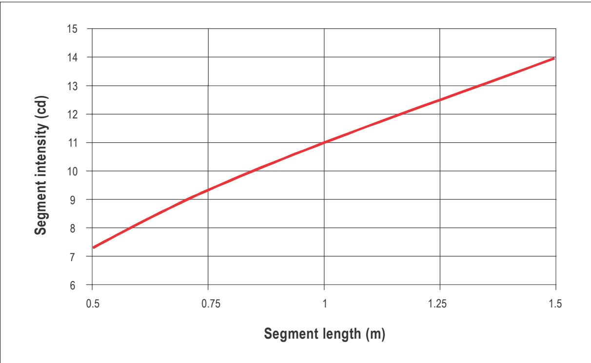
Figure II-5-C-2. TDPC segment intensity versus segment length
Note.— Given the minimum gap size of 0.5 m and the minimum coverage of 50 per cent, the minimum segment length is 0.5 m. The maximum segment length is given by selecting the minimum number of segments (16), the minimum access gap size (1.5 m) and the maximum coverage (75 per cent), resulting in a maximum segment length of 1.5 m for the 11.5 m standard TDPC diameter.
4.3.3 If a segment is made up of a number of individual lighting elements (e.g. LED’s), they should be of the same nominal performance (i.e. within manufacturing tolerances) and be equidistantly spaced throughout the segment to aid textural cueing. Minimum spacing between the illuminated areas of the lighting elements should be 3 cm and maximum spacing 10 cm.
4.3.4 On the assumption that the intensities of the lighting elements will add linearly at longer viewing ranges where intensity is important the minimum intensity of each lighting element (i) should be given by the formula:
$$ \mathsf { i } = \mathsf { I } / \mathsf { n } $$
where
I = required minimum intensity of segment at the ‘look down’ (elevation) angle (see Table II-5-C-6).
n = the number of lighting elements within the segment.
Note.— The maximum intensity of a lighting element at each angle of elevation should also be divided by the number of lighting elements within the segment.
4.3.5 If the segment comprises a continuous lighting element (e.g. fibre optic cable, electro luminescent panel), the element should be masked at 3.0 cm intervals on a 1:1 mark-space ratio to achieve textural cueing at short range,
4.4 Colour
4.4.1 The colour of the light emitted by the TDPC should be yellow and should conform to the chromaticity specifications defined in Annex 14, Volume I, Appendix 1, 2.3.1 (b).
Note.— The above assumes that solid state light sources are used. Annex 14, Volume I, Appendix 1, 2.1.1 (b), should be applied if filament light sources are used.
4.5 Serviceability
At least 90 per cent of the lighting elements should be operating for the TDPC to be considered serviceable.
5. THE CROSS MARKING REQUIREMENT
5.1 Configuration
5.1.1 The white cross marking should be lit using green right-angled lit chevron markings located adjacent to each of the four internal corners of the 9 m x 9 m white cross. Each chevron should be 1.5 m to 1.6 m x 1.5 m to 1.6 m in size and be spaced by 4.0 m to 4.5 m as shown in Figure II-5-C-3.
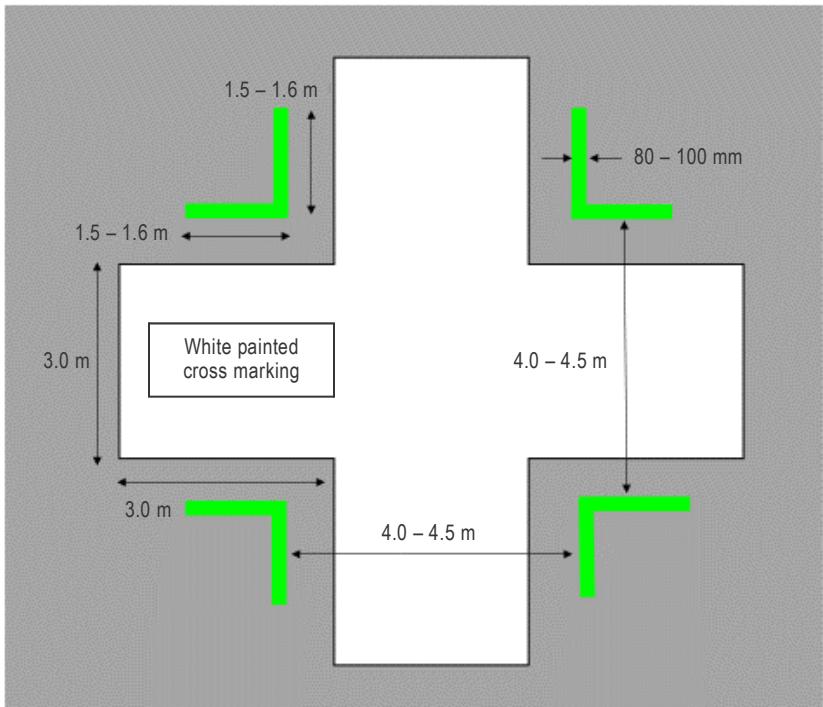
Figure II-5-C-3. Configuration and dimensions of heliport cross marking
5.1.2 The cross (chevron) markings should comprise sub-sections of between 80 mm and 100 mm wide. There are no restrictions on the length of the sub-sections, up to a maximum of 1.6 m but, where applicable, the gaps between them should not be greater than 10 cm. The mechanical housing should be coloured white and should be mounted onto white paint markings between 15 cm and 45 cm wide. To ensure the white chevron markings are conspicuous to a pilot operating by day, they should be outlined with a thin black line (typically 5 to 10 cm wide).
5.2 Mechanical constraints
5.2.1 The height of the cross fixtures (e.g. sub-sections) and any associated cabling should be as low as possible and should not exceed 25 mm above the surface of the heliport when fitted. To avoid a trip hazard, the lighting strips should not present any vertical outside edge greater than 6 mm without chamfering at an angle not exceeding 30° from the horizontal.
5.2.2 The overall effect of the lighting sub-sections and cabling on deck friction should be minimized. Wherever practical, the surfaces of the lighting sub-sections should meet the minimum deck friction limit coefficient (µ) of 0.6, e.g. on non-illuminated surfaces.
5.2.3 The cross-lighting components, fitments and cabling should be able to withstand a pressure of 2 280 kPa (331 lb/in2), without damage.
5.3 Light intensity
5.3.1 The intensity of the lighting for each 1.5 m limb of each chevron over all angles of azimuth is given in Table II-
5-C-6 below.
Note.— For the purposes of demonstrating compliance with this specification, a sub-section of the lighting forming the cross chevrons may be used. The minimum length of the sub-section should be 0.5 m.
Table II-5-C-6. Light Intensity of the 1.5 m limb of each cross chevron
| Elevation | Intensity | |
| Min | Max | |
| 2°to 12° | 2cd | 30 cd |
| >12° to 20° | 0.25 cd | 15cd |
| >20°to 90° | 0.1 cd | 5cd |
5.3.2 The cross chevrons should consist of the same sub-sections throughout.
5.3.3 If a sub-section of the cross chevrons is made up of individual lighting elements (e.g. LED’s), they should be of nominally identical performance (i.e. within manufacturing tolerances) and be equidistantly spaced within the subsection to aid textural cueing. Minimum spacing between the illuminated areas of the lighting elements should be 3 cm and maximum spacing 10 cm.
5.3.4 Due to the shorter viewing ranges for the cross and the lower intensities involved the minimum intensity of each lighting element (i) for all angles of elevation (0° to 90°) should be given by the formula:
i = I / n
where
I = required minimum intensity of the sub-section at the ‘look down’ (elevation) angle between 2° and 12° (see Table II-5-C-6).
n = the number of lighting elements within the sub-section.
Note.— The maximum intensity of each lighting element at any angle of elevation should be the maximum between 2° and 12° (see Table II-5-C-6) divided by the number of lighting elements within the sub-section.
5.3.5 If the cross chevrons are constructed from a continuous light element (e.g. ELP panels or fibre optic cables or panels), the luminance (B) of the 1.5 m arms of the chevrons should be given by the formula:
B = I / A
where
I = intensity of the limb (see Table II-5-C-6).
A = the projected lit area at the ‘look down’ (elevation) angle.
5.3.6 If the sub-section comprises a continuous lighting element (e.g. ELP, fibre-optic cable), the element should be masked at 3.0 cm intervals on a 1:1 mark-space ratio to achieve textual cueing at short range,
5.4 Colour
The colour of the cross chevrons should be green and should conform to the chromaticity specifications defined in Annex 14, Volume I, Appendix 1, 2.3.1 (c).
Note.— The above assumes that solid state light sources are used. Annex 14, Volume I, Appendix 1, 2.1.1 (c), should be applied if filament light sources are used.
5.5 Serviceability
At least 90 per cent of the lighting elements in each of the four chevron markings should be operating for the cross marking to be considered serviceable.
6. GENERAL CHARACTERISTICS
6.1 Requirements
6.1.1 All lighting components should be tested by an independent test house. The photometrical and colour measurements performed in the optical department of this test house should be accredited according to the version of EN ISO/IEC 17025 current at the time of testing. The angular sampling intervals should be: every 10° in azimuth; every 1° from $0 ^ { \circ }$ to 10°, every 2° from 10° to 20° and every 5° from 20° to 90° in elevation.
6.1.2 With regard to the attachment of the TDPC and cross chevrons to the heliport, the critical failure mode requiring consideration, as a result of the shear loads that are generated during helicopter landings, is the detachment of elements of the TDPC and cross lighting. The maximum horizontal load may be assumed to be that defined in Chapter 3, Case A, paragraph d) i.e. the maximum take-off mass (MTOM) of the largest helicopter for which the heliport is designed multiplied by 0.5, distributed equally between the main undercarriage legs. The requirement applies to components of the circle and cross lighting having an installed height greater than 6 mm and a plan view area greater than, or equal to, 200 cm2. Recessed fittings should be used wherever possible. Use of raised fittings (e.g. domed nuts) should be minimized and, in any event, should not protrude by more than 6 mm above the surrounding surface without chamfering at an angle not exceeding 30° from the horizontal.
Note 1.— For example, a horizontal load of 35.8 kN should be assumed for a helicopter MTOM of 14 600 kg.
Note 2.— For components having plan areas up to and including 1 000 cm2, the horizontal load may be assumed to be shared equally by all fasteners provided that they are approximately equally spaced. For larger components, the distribution of the horizontal loads should be considered.
6.1.3 Provision should be included in the design and installation of the system to allow for the effective drainage of the heliport areas inside the TDPC and the cross lighting (see Chapter 3). The design of the lighting and its installation should be such that the residual fluid retained by the circle and cross lighting when mounted on a smooth flat plate with a slope of 1:100, a fluid spill of 200 litres at the centre of the helipad will drain from the circle within 2 minutes. The maximum drainage time applies primarily to aviation fuel, but water may be used for test purposes. The maximum drainage time does not apply to fire-fighting agents.
Note.— Drainage may be demonstrated using a mock-up of a one quarter segment of a helipad of D-value of at least 20 m, configured as shown in Figure II-5-C-4, and a fluid quantity of 100 litres. The surface of the test helipad should have a white or light-coloured finish and the water (or other fluid used for the test) should be of a contrasting colour (e.g. by use of a suitable dye) to assist the detection of fluid remaining after 2 minutes.
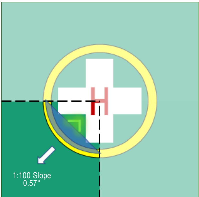
Figure II-5-C-4. Configuration of quarter segment drainage test mock-up
6.2 Other considerations
6.2.1 All lighting components and fitments should meet safety regulations relevant to a heliport environment such as flammability and be tested by a notified body in accordance with applicable directives.
6.2.2 All lighting components and fitments installed on the surface of the heliport should be resistant to attack by fluids such as fuel, hydraulic fluid, helicopter engine and gearbox oils. The components used for de-icing, cleaning and fire-fighting should also be resistant to any fluids used in the assembly or installation of the lighting, e.g. thread locking fluid, UV light, rain, snow and ice. Components should be immersed in each of the fluids individually for a period representative of the likely exposure in-service and then checked to ensure no degradation of mechanical properties (i.e. surface friction and resistance to contact pressure), any discolouration or any clouding of lenses/diffusers. Any other substances that may come into contact with the system that may cause damage should be identified in installation and maintenance documentation.
6.2.3 All lighting components and fitments that are mounted on the surface of the heliport should be able to operate within a temperature range appropriate for the local ambient conditions.
6.2.4 All cabling should utilize low smoke/toxicity, flame retardant cable. Any through-the-deck cable routing and connections should use sealed glands, type approved for heliport use.
6.2.5 All lighting components and fitments should meet IEC International Protection (IP) standards according to IEC 60529 appropriate to their location, use and recommended cleaning procedures. The intent is that the equipment should be compatible with deck cleaning activities using pressure washers and local flooding (i.e. puddling) on the surface of the heliport. It is expected that this will entail meeting at least IP66 (dust tight and resistant to powerful water jetting).
IP67 (dust tight and temporary submersion in water) and/or IP69 (dust tight and resistant to close -range high pressure, high temperature jetting) should also be considered and applied where appropriate.
Note.— Except where flush mounted (e.g. where used to delineate the landing area from an adjacent parking area), perimeter lights need only meet IP66. Lighting equipment mounted on the surface of the heliport (e.g. circle and cross lighting) should also meet IP67. Any lighting equipment that is to be subject to high pressure cleaning (i.e. lighting mounted on the surface of the helideck such as the circle and cross lighting) should also meet IP69.
6.2.6 Control panels that may be required for heliport lighting systems are not covered in this document. It is the responsibility of the engineering contractor to select and integrate control panels into the installation safety and control systems and to ensure that all such equipment complies with the relevant engineering standards for design and operation.
HELIPORT EMERGENCY RESPONSE
6.1 HELIPORT EMERGENCY PLANNING
6.1.1 General
6.1.1 Heliport emergency planning is the process of preparing a heliport to cope with an emergency that takes place at the heliport or in its vicinity. This process minimizes the impact of an emergency by saving lives and restoring the heliport to normal operations as soon as practical.
6.1.2 Every heliport should establish an emergency plan commensurate with the complexity of helicopter operations and of other activities conducted at, or in the vicinity of, the heliport to deal with helicopter emergency situations.
6.1.3 The plan should include a set of instructions dealing with the arrangements designed to meet emergency conditions and steps that should be taken to see that the provisions of the instructions are periodically tested.
6.1.2 Plan contents
6.1.2.1 Type of emergencies
6.1.2.1.1 The heliport emergency plan should include possible emergencies to plan for and how to initiate the plan for each emergency.
6.1.2.1.2 Possible emergencies:
a) may involve aircraft:
- accidents;
i) helicopter on-heliport; and
ii) helicopter off-heliport (in the vicinity):
– land; and
water;
- incidents;
i) helicopter on ground;
ii) sabotage including bomb threat; and
iii) unlawful seizure;
b) not involving helicopter:
-
fire on the building and/or nearby buildings;
-
sabotage including bomb threat;
-
natural disaster;
-
dangerous goods occurrences; and
-
medical emergencies;
c) compound emergencies:
-
helicopter/structures;
-
helicopter/fuelling facilities;
-
helicopter/helicopter; and
-
helicopter/aeroplane.
6.1.2.1.3 The aircraft emergencies for which services may be required are generally classified as:
a) local standby: when a helicopter approaching the heliport is known, or is suspected, to have developed some defect, but the problem is not such as would normally involve any serious difficulty in effecting a safe landing;
b) full emergency: when it is known that a helicopter approaching the heliport is, or is suspected to be, in such trouble that there is danger of an accident; and
c) helicopter accident: a helicopter accident which has occurred on or in the vicinity of the heliport.
6.1.2.2 Cooperating agencies
6.1.2.2.1 The heliport emergency plan should identify agencies that could assist or respond to an emergency at the heliport or in its vicinity. Names of agencies on and off the heliport, for each type of emergency, with telephone numbers or other contact information, should be included. The plan should also identify the role of each agency for each type of emergency, and a list of pertinent on-heliport services available with telephone numbers or other contact information.
6.1.2.2.2 The heliport emergency plan should set out the procedures for coordinating the response of heliport agencies or services (air traffic services unit, firefighting services, heliport administration, medical and ambulance services, aircraft operators, security services and police) and the response of agencies in the surrounding community (fire departments, police, medical and ambulance services, hospitals, military and harbour patrol and/or coastguard agencies). Copies of any written agreements with other agencies for mutual aid and the provision of emergency services should be contained within the emergency plan.
6.1.2.3 Specified locations
6.1.2.3.1 The emergency organization should specify rendezvous point(s) and staging area(s) for the assisting services involved. A rendezvous point is a prearranged reference point, i.e. road junction, crossroads or other specified place, to which personnel or vehicles responding to an emergency situation initially proceed to receive directions to staging areas and/or the accident or incident site.
6.1.2.3.2 It is recommended that two grid maps (or equivalent) be provided: one map depicting the confines of heliport access roads, location of water supplies, rendezvous points, staging areas, railways, highways, difficult terrain, places with dangerous goods or harmful fluids, etc., and the other map of surrounding communities depicting appropriate medical facilities, access roads, rendezvous points, etc., within a distance of approximately 4 km from the heliport reference point. Where more than one grid map (or equivalent) is used, the scaling lines should not conflict and should be immediately identifiable to all participating agencies.
6.1.2.3.3 Copies of the map(s) should be kept at the emergency operations centre, the heliport operations office, heliport and local fire stations in the vicinity, all local hospitals, police stations, local telephone exchanges, and other similar emergency and information centres in the area.
6.1.2.4 Emergencies in difficult environments
6.1.2.4.1 The heliport emergency plan should include the availability of, and coordination with, appropriate specialist rescue services to respond to emergencies where a heliport is located close to water or swampy areas and/or where a significant portion of approach or departure operations takes place over these areas.
6.1.2.4.2 At those heliports located close to water, swampy areas or difficult terrain, the heliport emergency plan should include the establishment, testing and assessment at regular intervals of a predetermined response for the specialist rescue services.
6.1.2.5 Review and testing of the heliport emergency plan
6.1.2.5.1 The heliport emergency plan should be reviewed and its information updated at least yearly. After an actual emergency, a review of the heliport emergency plan should be conducted to identify any deficiencies arising as a result of the actual emergency.
6.1.2.5.2 The emergency plan should be regularly tested and should include the agencies identified in 6.1.2.2.
6.2 RESCUE AND FIREFIGHTING SERVICE (RFFS)
Note 1.— The specifications addressed in this section need not be applied to new builds, or replacement of existing systems, or part thereof, until 1 January 2023.
Note 2.— In the following text, the term ‘limited-sized heliport’ is used to describe a heliport where the firefighting capacity is concentrated at the FATO/TLOF and there is no requirement to move foam and/or water dispensing equipment.
6.2.1 Introduction
6.2.1.1 The principal objective of a rescue and firefighting response is to save lives. For this reason, the provision of a means of dealing with a helicopter accident or incident, occurring within the immediate vicinity (i.e. within the designated response area) of a heliport, assumes primary importance because it is within the response area that there are the greatest opportunities for saving lives by a dedicated heliport rescue and firefighting response. This will have to assume, at all times the possibility of, and need for, extinguishing a fire which may occur either immediately following a helicopter accident or incident, or at any time during a subsequent rescue phase.
6.2.1.2 The most important factors bearing on effective escape in a survivable helicopter accident are the speed of initiating a response and the effectiveness of that response. Where a heliport is located on top of a building that is occupied, it is also paramount, for the protection of inhabitants in the building beneath that any fire situation occurring at the heliport be rapidly brought under control. On a purpose-built heliport constructed of aluminium or steel, any effect the fire may have on the structural integrity of the helideck and/or its supporting structure has to be considered. In the event of a fire at a purpose-built heliport, a full structural analysis should be undertaken post-accident, and before helicopter operations are permitted to resume.
6.2.1.3 For a surface-level heliport, especially where it contains a remote FATO, a suitable vehicle may need to be provided to meet the response time objective stated in Annex 14, Volume II, Chapter 6. Where a heliport is located close to water, swampy areas or in difficult terrain and where a significant portion of the approach and departure operation takes place over these areas, an assessment will need to be carried out to determine if specialist RFFS equipment appropriate to specific hazards and risks should be made available. This may include, for example, a rescue boat.
6.2.1.4 Prior to selection of a dedicated heliport rescue and firefighting response (RFFR), the following should be considered: concept and definitions for the characteristics of helicopters; types of heliport facility they may be expected to operate to; and effective distribution of primary extinguishing agent to address a worst case crash and burn.
6.2.1.5 A heliport operator should also have a good understanding of emerging technologies that demonstrate effective methods for delivering primary extinguishing agents. To provide a speedy and effective response, a heliport operator should be able to determine the practical critical area, the response area and response time objectives for their facility.
6.2.2 Determining the required level of RFFS at a heliport
6.2.2.1 A risk assessment should be performed to first determine whether there is a need for rescue and firefighting equipment and services at surface level heliports and at elevated heliports located above unoccupied structures. This assessment should include staffing models for heliports without a dedicated RFFS and with only occasional movements, and for initiating the heliport emergency response.
6.2.2.2 The following photographs illustrate elevated heliports above what are regarded as unoccupied areas. These are for illustrative purposes only and are by no means exhaustive. It is the responsibility of the State of Operation to determine what is classed as an unoccupied area beneath a heliport and therefore is subject to the risk assessment process described at 6.2.2.4.
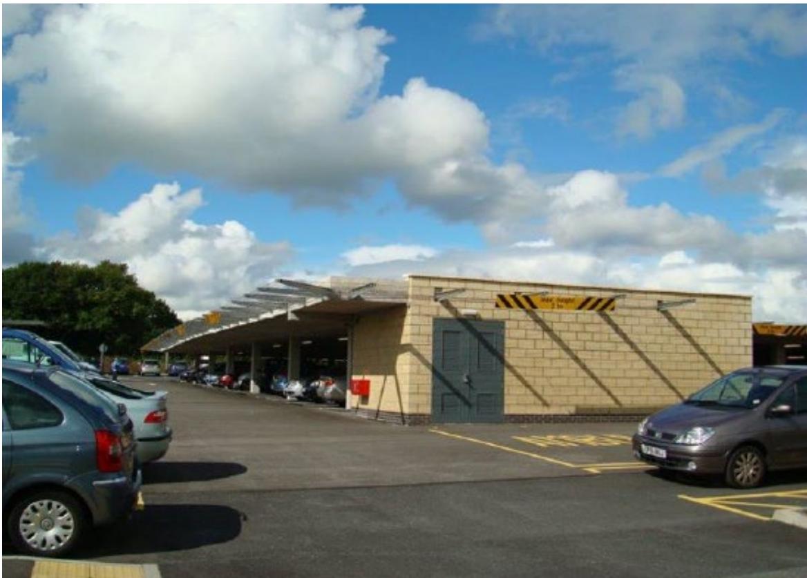
Figure II-6-1. Heliport above unoccupied building
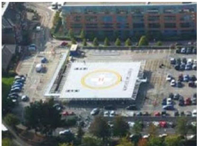
Figure II-6-2. Heliport above car park
6.2.2.3 In each illustration, the area underneath the heliport is intended for vehicle parking only. The important distinction to make is that no one is permanently residing beneath the heliport, and it is possible to restrict the movement of persons to and from vehicles during helicopter operations, to ensure that as far as reasonably practicable no one is left in their vehicle during helicopter landing and take-off.
6.2.2.4 The following factors need to be considered in any risk assessment, but it is the responsibility of the State of Operation to determine appropriate threshold limits, including:
a) number of movements planned/ unplanned;
b) frequency of movements;
c) total number of helicopters in use at the site during peak periods;
d) type of movements, i.e. whether conducting commercial air transport (CAT) and/or general aviation (GA);
e) number of passengers;
f) types of helicopters in use, their certification status with respect to crashworthiness (see Appendix B to Chapter 6) and their performance characteristics;
g) size and complexity of the response area, e.g. other helicopters are present in apron area;
h) nature of the terrain, e.g. located near water or swampy areas;
i) whether the heliport is elevated or at surface level;
j) whether the heliport is in a congested or non-congested environment;
k) availability of the local fire and rescue services, i.e. how rapidly can services respond to an incident on the heliport;
l) types of helicopters and specific hazards, e.g. construction materials are used in airframes such as composites, i.e. man-made mineral fibres (MMMF); and
m) whether or not an emergency response plan has been established.
6.2.3 Heliport staffing levels
6.2.3.1 The degree of complexity of the heliport and the emergency planning arrangements in place will help to inform heliport staff to execute the heliport emergency plan effectively. The number of personnel used and their given training, are decisions for heliport management and should be fully documented. In order to establish staffing levels, a task/resource analysis should be carried out. An example is provided in Appendix A to Chapter 6.
6.2.3.2 The heliport emergency plan exists to identify agencies that could be of assistance in responding to an emergency at the heliport, or in its vicinity. This could include, but may not be limited to, a helicopter crash, whether or not resulting in a post-crash fire, or a medical emergency or a dangerous goods occurrence. If, due in particular to a low number of movements, a dedicated RFFS is not provided, whether at a surface level heliport or elevated heliport located above an unoccupied structure, there should be a specified method for invoking the heliport emergency plan.
6.2.3.3 Where present, designated personnel should invoke the heliport emergency plan. If the heliport is unattended, the heliport emergency plan should be activated remotely.
6.2.4 Level and method of protection
6.2.4.1 Helicopter characteristics and parameters to be considered
6.2.4.1.1 For the defined areas of a heliport, overall length and maximum take-off mass of the design helicopter are the critical parameters for a designer. For a dedicated firefighting service (FFS) at a heliport, the critical parameters are fuselage length and fuselage width. These dimensions are usually available in the helicopter’s Type Certificate and in the helicopter flight manual but are presented for common types in Table II-6-1 (Table II-6-1 is configured on an ascending scale of overall length (D-value)).
6.2.4.1.2 The fuselage consists of the central portion of the helicopter designed to accommodate the aircrew and the passengers and/or cargo. Fuselage length is often presented (conservatively) in flight manuals as the distance between the nose of the helicopter and the end of the tail boom, and fuselage width as the overall width of the occupied portion of the helicopter excluding the undercarriage.
6.2.4.1.3 To assist designers, Table II-6-1 presents the fuselage dimensions of common helicopter types. The table is not intended to be exhaustive and for types not listed in the table, a designer will have to source the information from official documentation (i.e. the helicopter’s Type Certificate or flight manual). Notwithstanding this, the right-hand column specifies a broad firefighting category from H0 to H3, which is based on Table 6-1 of Annex 14 Volume II, Chapter 6 but includes a discretionary 10 per cent tolerance applied to the upper limits quoted for fuselage length and fuselage width in Table II-61.
6.2.4.1.4 Therefore, for a given operation, there is the option either to apply a type-specific critical area calculation using the formula:
L x (W + W1) where:
L = fuselage length
W = fuselage width
W1 = additional width factor of 4 m
or, alternatively, to adopt the broader ‘default’ figures in Table II-6-1, which reconcile with H0, H1, H2 or H3 as appropriate (with the 10 per cent tolerance factored in).
Note.— A given helicopter is required to be within the limits, including tolerances, for both parameters, fuselage length and fuselage width, to take advantage of a given FFS category. If either dimension, when factoring-in tolerances, is exceeded, that type should be recorded against the higher FFS category.
6.2.4.1.5 For the critical area calculation where primary extinguishing agent is applied in a dispersed (spray) pattern (see 6.2.4.2.5), the formula described in the paragraph above is not applicable. In this case the practical critical area is required to assume protection, i.e. application of primary extinguishing agent, to all parts of the TLOF, and to the extent that it is load bearing, to the FATO also.
Table II-6-1. Overall length and fuselage characteristics for common helicopter types
| Type | D-value(metres) | Fuselage length | Fuselage width* | FFS categoryHO to H3 |
| Robinson R22 | 8.76 | 6.30 | 1.12 | HO |
| Robinson R44 | 11.70 | 9.10 | 1.30 | H1 |
| Robinson R66 | 11.66 | 9.00 | 1.47 | H1 |
| H120 | 11.52 | 9.60 | 1.50 | H1 |
| H125 (AS350 B3) | 12.94 | 10.93 | 1.87 | H1 |
| H130 | 12.60 | 10.68 | 2.03 | H1 |
| MD902 | 12.37 | 10.39 | 1.32 | H1 |
| Bell 206BII | 11.95 | 9.51 | 1.40 | H1 |
| Bölkow Bo 105 | 12.00 | 8.81 | 1.58 | H1 |
| EC 135 T2+ | 12.20 | 10.20 | 1.56 | H1 |
| H135 | 12.26 | 10.20 | 1.56 | H1 |
| Bel1 407 | 12.70 | 10.57 | 1.47 | H1 |
| Bell 429 | 13.00 | 11.73 | 1.63 | H1 |
| Bell 206L IV | 12.96 | 10.56 | 1.40 | H1 |
| Eurocopter AS355 | 12.94 | 10.93 | 1.87 | H1 |
| BK117 | 13.00 | 9.98 | 1.60 | H1 |
| Bell 427 | 13.00 | 11.13 | 1.60 | H1 |
| Kamov Ka226 | 13.00 | 8.61 | 3.22 | H3 |
| Leonardo A109 | 13.05 | 11.45 | 1.62 | H1 |
| Leonardo A119 | 13.02 | 11.14 | 1.67 | H1 |
| Eurocopter EC145C-2e | 13.03 | 10.20 | 1.73 | H1 |
| H145 | 13.64 | 11.69 | 1.73 | H1 |
| Dauphin AS365 N2 | 13.68 | 11.63 | 2.03 | H1 |
| Leonardo 169 | 14.65 | 12.19 | 2.15 | H1 |
| Leonardo 189 | 17.60 | 14.60 | 2.55 | H2$ |
| H175 | 18.06 | 15.68 | 2.25 | $H2$ |
| Dauphin AS365 N3 | 13.73 | 11.63 | 2.03 | H1 |
| H155 (EC 155B1) | 14.30 | 12.71 | 2.05 | H1 |
Part II. Onshore heliports Chapter 6. Heliport emergency response
| Type | D-value(metres) | Fuselage length | Fuselage width* | FFS categoryHO to H3 |
| Bell 222 | 15.33 | 12.50 | 1.62 | H1 |
| Bell 230 | 15.38 | 12.97 | 1.65 | H1 |
| Bell 430 | 15.29 | 13.44 | 1.70 | $H2$ |
| Kamov Ka32** | 15.90 | 11.21 | 3.80 | H3 |
| Kamov Ka62 | 15.60 | 13.46 | 2.50 | H2 |
| Sikorsky S76C | 16.00 | 13.20 | 2.13 | H1 |
| Leonardo 139 | 16.63 | 13.77 | 2.26 | $H2$ |
| Bell 412 | 17.13 | 12.91 | 2.44 | H2 |
| Bell 205 | 17.46 | 12.92 | 2.44 | $H2$ |
| Bell 212 | 17.46 | 14.00 | 2.64 | $H2$ |
| Bell 214B | 18.52 | 13.77 | 2.44 | H2 |
| H215 (AS332 C1e) | 18.70 | 14.82 | 2.00 | $H2$ |
| H215 (AS332L1-e) | 18.70 | 15.58 | 2.00 | $H2$ |
| PZL-SWIDNIK W-3A Sokol | 18.79 | 13.78 | 1.75 | $H2$ |
| Bell 214ST | 18.95 | 14.97 | 3.11 | H3 |
| Super Puma AS332L2 | 19.50 | 16.79 | 2.00 | $H2$ |
| H225 (EC 225 LP) | 19.50 | 16.79 | 2.00 | $H2 |
| Sikorsky S92A | 20.88 | 17.10 | 2.50 | H3 |
| Sikorsky S61N | 22.20 | 18.72 | 2.16 | H3 |
| AW101 | 22.80 | 19.51 | 2.80 | H3 |
| Mil Mi38 | 25.22 | 19.95 | 2.36 | H3 |
| Mil Mi8 | 25.35 | 18.17 | 2.50 | H3 |
| *An additional width factor of 4m (W1) is to be applied as part of the practical critical area calculation.* Data from EASA type certificate data sheet - the with could include the empennage; i that is so it might be prudentto refer to the RFM and adjust the FFS category if necessary. The category has been assigned with the assumptionthat the empennage will be excluded from the width.Note: The dimensions above have been taken from "The Official Helicopter Blue Book@". Actual dimensions should beverified against the RFM for the type(s) being used. | ||||
6.2.4.2 Practical critical area
6.2.4.2.1 To determine the amount of water required for foam production it is first necessary to calculate a practical critical area (in m2) which is multiplied by the application rate (in L/min/m2) of the respective foam performance level to determine the discharge rate for foam solution (in L/min). By multiplying the discharge rate by the discharge duration, this determines the amount of water needed for foam production.
6.2.4.2.2 The assumptions used to determine practical critical area (helicopters) depend on whether primary extinguishing agent (usually foam) is initially applied in a solid stream (jet) application or in a dispersed (spray) pattern.
6.2.4.2.3 A solid stream is used for firefighting when range of application is essential. In this case the practical critical area is limited to the fuselage dimensions of the helicopter plus an additional width factor (as specified in the note to Table I-6-1 above). Delivering foam solution for initial attack from a fixed monitor system (FMS) located on the periphery of the heliport (see Figure II-6-3), or from a hose-line, in a jet configuration, are examples of typical solid stream applications. In each case, once the fire has been brought under control during the initial attack, there is usually a facility to adjust the nozzle, changing the throughput of equipment from a solid stream application to a dispersed pattern, i.e. the nozzle is adjusted from a jet to a spray (fog) pattern. Where applicable, this provides a safer environment for rescue crews to approach the accident/ incident location.
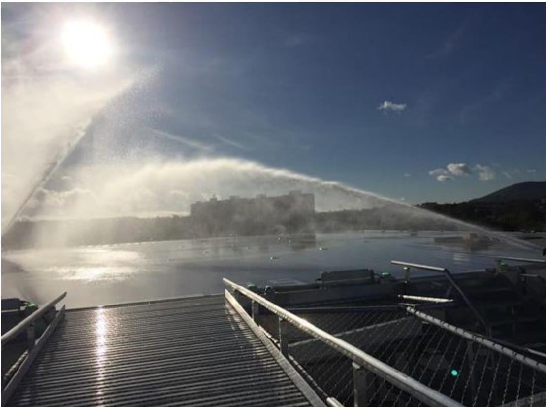
Figure II-6-3. Solid stream application utilising a fixed monitor system (FMS)
6.2.4.2.4 The practical critical area (helicopters), where primary extinguishing agent is applied as a solid stream-jet, is determined by multiplying the maximum fuselage length for a given firefighting category (H0 to H3) by the maximum fuselage width of the same category, then applying an additional width factor (W1) of 4 m. This has been presented in detail in Table II-6-1 (where discretionary 10 per cent upper limit tolerances are also applied). Alternatively, by knowing the fuselage length and width dimensions, a practical critical area calculation can be applied to any specific type of helicopter; this has an application, in practice, when only one type of helicopter is being operated at a heliport.
6.2.4.2.5 A dispersed pattern is used at heliports when it is necessary to deliver foam and/or water at shorter ranges, combining greater coverage with a more effective surface application of the primary extinguishing agent. Here, due to the greater coverage of primary extinguishing agent applied in a dispersed spray pattern, the assumed practical critical area has to be much larger than in a case where primary extinguishing agent is applied in a solid stream (jet). A particularly effective way of delivering primary extinguishing agent in a dispersed pattern is through a Deck Integrated Fire Fighting System (DIFFS) (see Figure II-6-4) typically consisting of a series of flush-mounted nozzles positioned over the surface of the practical critical area which, upon activation, are capable of delivering primary extinguishing agent to the entire loadbearing area of the heliport.
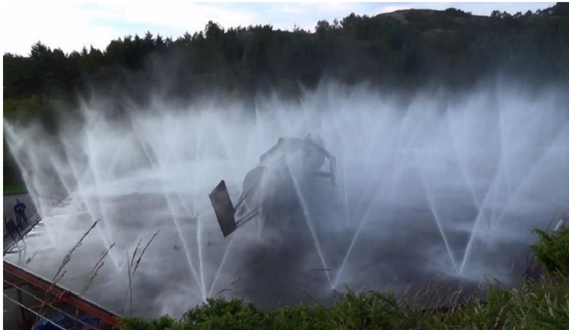
Figure II-6-4. Example of a dispersed pattern application utilising DIFFS
Note.— In some cases, fixed nozzles may sit very slightly proud of the surrounding deck surface prior to activation, and so it becomes unnecessary for them to physically ‘pop-up’ on activation of the system for this type of nozzle to be effective.
6.2.4.2.6 The practical critical area (helicopters) where primary extinguishing agent is applied in a dispersed (spray) pattern, is predicated on the dimensions of the operating area that needs to be protected. For an onshore purpose built, or limited-sized heliport (e.g. an elevated heliport at rooftop level), the practical critical area is assumed to accommodate the whole load-bearing area which always includes the TLOF, and to the extent that it is a load-bearing surface, the FATO also. In this case, the area to be considered is based on the specific shape of the TLOF, and where applicable, the shape of the FATO.
6.2.4.2.7 Another form of foam dispensing equipment, capable of delivering primary extinguishing agent in a dispersed pattern, is a ring-main system (RMS). In this case, equally spaced nozzles are located around the perimeter of the practical critical area, just above the surface, capable of directing extinguishing agent from the perimeter towards the centre of the landing area. Given the relative ranges at which nozzles are expected to perform, especially in windy conditions, it has been established through practical testing that sole use of an RMS has proven ineffective for TLOFs which are greater than 20 m diameter. In this case, an RMS could only be utilised effectively if supplemented by DIFF nozzles in the centre of the TLOF (a combination solution of RMS plus DIFFS). However, in the case of a large new-build heliport, it is probably more cost-effective and efficient, to provide a full DIFFS.
6.2.4.3 Fixed foam application systems (FFAS)
6.2.4.3.1 When installed at a heliport, a fixed foam application system (FFAS) should deliver a primary foam extinguishing agent at the required application rate and over the assumed practical critical area. An FFAS may include, but not necessarily be limited to, an FMS), a DIFFS or a RMS. A variation on an FFAS is a fixed application system (FAS) capable of applying water-only in a dispersed pattern. An FAS is only permitted when it is used in tandem with a passive fire-retarding surface (see 6.2.4.6.2).
Note 1.— Where an FMS is installed, trained monitor operators, where provided, should be positioned on at-least the upwind location to ensure the primary extinguishing agent is directed efficiently to the seat of the fire.
Note 2.— Compressed air foam systems (CAFS) may be considered, with foam distributed through a DIFFS using Performance Level B foam (BCAFS). Fire suppression capabilities are enhanced by injecting compressed air into the foam to generate an effective solution to control a fire on the heliport. This type of foam has a tighter, denser bubble structure than standard foams, which allows it to penetrate deeper into the fire before the bubbles are broken down. BCAFS rapidly controls a fire by smothering it (starving it of oxygen), by diminishing heat, using trapped air within the bubble structure, and by disrupting the chemical reaction needed for a fire to continue. Consequently, the opportunity presents to deliver BCAFS at a lower application rate than would otherwise be required for a Standard Level B foam.
6.2.4.3.2 An FFAS may be used at a limited-sized heliport where there is no requirement to physically move foam dispensing equipment towards the fire (hence the equipment is fixed in location). Where foam dispensing equipment is required to be moved towards the accident/ incident location, this is classed as a portable foam application system (PFAS) — see 6.2.4.5.
6.2.4.4 Additional hand-controlled foam branches for the application of aspirated foam
6.2.4.4.1 Not all fires are capable of being accessed by fixed foam application systems (FFAS) delivering foam as a solid stream. Further, in certain scenarios, their use may endanger helicopter occupants who are seeking to escape from the fire. Therefore, in addition to solid stream FFAS, there should be the ability to deploy at least two deliveries with handcontrolled foam branch pipes for the application of aspirated foam at a minimum rate of 225-250 litres/minute through each hose line.
6.2.4.4.2 A single hose line, capable of delivering aspirated foam at a minimum application rate of 225-250 litres/minute, may be acceptable where the hose line is a sufficient length, and the hydrant system of sufficient operating pressure for the effective distribution of foam to any part of the practical critical area, regardless of wind strength or direction.
6.2.4.4.3 Taking account of the open-air environment in which equipment is expected to perform, a low expansion foam should be used. An inline foam inductor is provided to induct the foam concentrate into the water stream to supply a proportioned solution of concentrate and water to foam producing equipment. The inline inductor should be set to the appropriate rate corresponding to the strength of the foam concentrate used e.g. 3 per cent or 6 per cent.
6.2.4.4.4 The hose line(s) provided should be capable of being fitted with a branch pipe able to apply water in the form of a jet or spray pattern for cooling, or for specific firefighting tactics.
6.2.4.5 Portable foam application systems (PFAS)
6.2.4.5.1 For some heliports, it becomes necessary to move primary extinguishing agent-dispensing equipment towards the accident or incident location, for example at a surface level heliport operating a remote FATO (analogous to a fixed wing runway operation at an airport, where the fire vehicle has to be positioned from a location remote to the runway).
6.2.4.5.2 The ability to transport the equipment to the accident location means it is classed as a PFAS which, having been moved to the fire location is then capable of distributing primary extinguishing agent at the required application rate over the assumed practical critical area. A PFAS may include, but not necessarily be limited to, hand-controlled portable foam branch pipes capable of being pulled across the heliport surface by trained personnel (see 6.2.4.4), and monitors or foam cannons that are mounted on an appropriate rescue and firefighting vehicle and then transported to the scene of an accident as part of the rescue and firefighting response for the heliport.
6.2.4.6 Solid plate heliports and passive fire-retarding surfaces
6.2.4.6.1 Most new-build purpose-built heliports are either constructed of aluminium or steel with aluminium or steel support structures. A solid plate surface is set to an appropriate fall or camber (typically 1:100) which allows burning fuel to drain across the solid surface of the heliport into a suitable drainage collection system, whether the fall or camber emanates from the centre of the TLOF or at the perimeter edge. An example of a DIFFS installed on a solid plate surface at an elevated heliport is shown in Figure II-6-5.
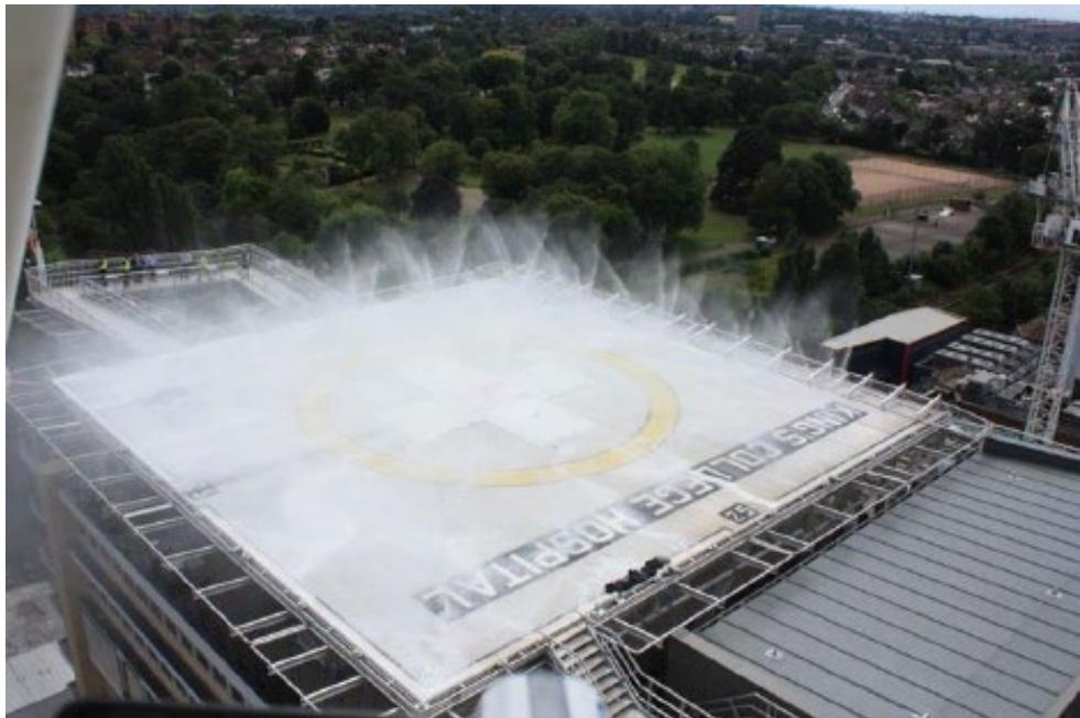
Figure II-6-5. A foam DIFFS on a solid plate surface at an elevated heliport
Note.— While this description is most commonly met by a purpose-built arrangement, it could also be a nonpurpose-built structure, such as the roof of a building, typically made of concrete. The important distinction, from a firefighting perspective, is that in all cases, whether purpose built or non-purpose built, a solid plate surface is by definition non-porous, i.e. impervious to liquids – therefore there is no reasonable expectation that fluids, i.e. aviation fuel discharging from ruptured tanks in a crash and burn, will rapidly drain away, other than through dissipation due to a mild slope on the solid plate surface.
6.2.4.6.2 As an alternative to the solid-plate surface, many manufacturers now give an option to install a passive fireretarding surface which, at a purpose-built heliport is constructed in the form of a perforated surface or grating, containing numerous holes that allow burning fuel to rapidly drain through the surface of the heliport, in some cases to an intermediate safety screen and that functions to extinguish the fire (by starving it of oxygen) permitting, now un-ignited, fuel to drain away to a safe collection area. Other systems (like the design pictured in Figure II-6-6) have no safety screen inside the deck chambers but function by removing the heat from a fire via novel hole sizes and patterns.
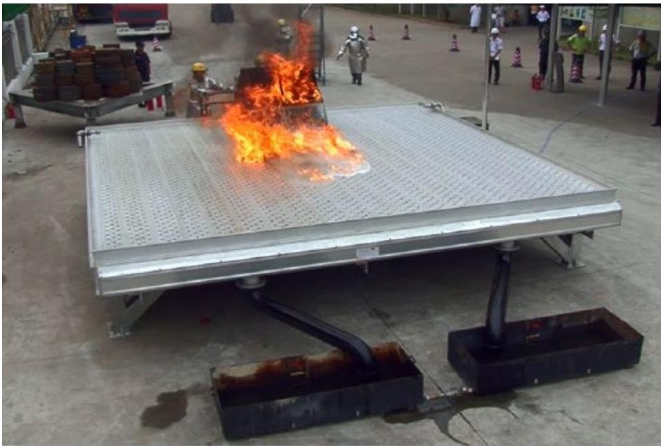
Figure II-6-6. A fire test on a passive fire-retarding surface (200 L of burning fuel)
6.2.4.6.3 The good thermal conductivity of aluminium, coupled with the fuel flow profile, facilitates a rapid cooling effect on the burning fuel, extinguishing any fire that flows into the decking. These systems, when used in combination with a water-only DIFFS, have been demonstrated to show that any residual fire burning over the surface of the heliport remains insignificant given that the fuel source is constantly draining away to a safe area. Figure II-6-7 illustrates on a passive fire-retarding surface how burning fuel rapidly drains away to collection troughs (approximately 22 seconds after the start of the fire).
Note.— Practical testing (see Figures II-6-6 and II-6-7) has consistently demonstrated that even without the addition of water for cooling, a passive fire-retarding surface is proven to be effective in suppressing running fuel fires by channelling liquids away via the holes on the surface, through the decking sub surface into the perimeter gutters and onwards into the drainage system.
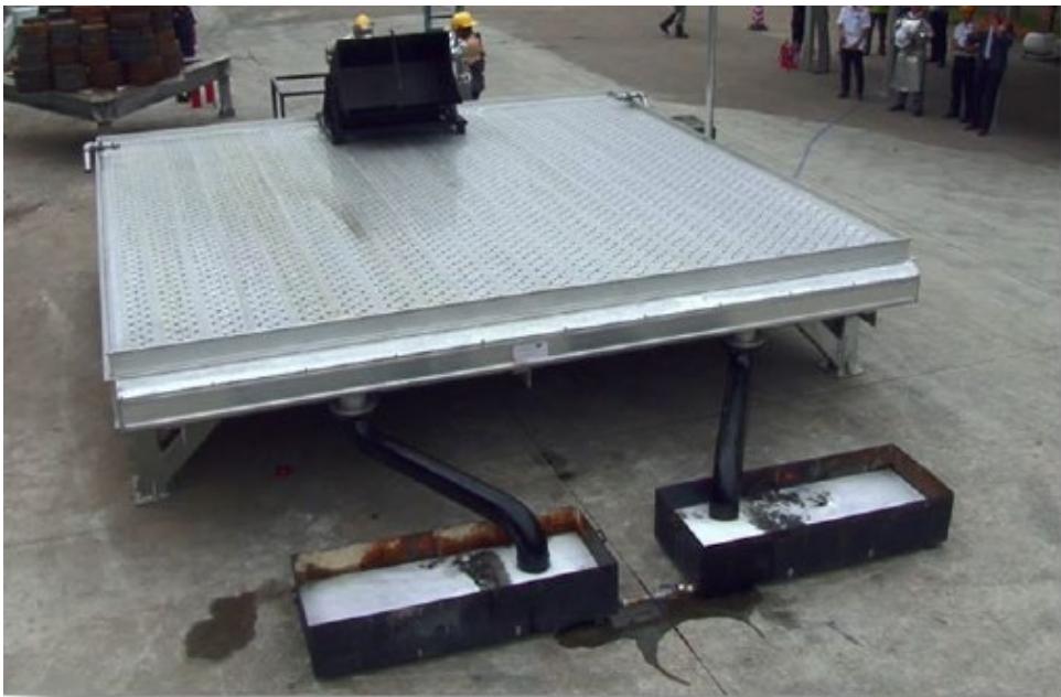
Figure II-6-7. A fire test on a passive fire-retarding surface (180 L of fuel is collected)
6.2.4.6.4 Where a passive fire-retarding surface is selected in lieu of a solid plate surface, the requirement to provide foam for primary extinguishing agent is removed since most of the fuel is directed immediately away from the surface restricting the intensity of the subsequent fire and what residual fire does remain above the surface is insignificant and can be extinguished with the use of water (see Figure II-6-8 which shows an elevated heliport with a water-only DIFFS coupled with a passive fire-retarding surface).
Note.— Apart from the potential for a reduction in helpful ground effect, there is also a practical consideration for this type of porous design in-so-far-as fuel is removed from the surface by numerous holes, so too is the primary extinguishing agent. Consequently, as it is not possible to form an effective foam blanket on a perforated surface, a significant benefit of using foam is nullified. A passive fire-retarding surface is best used with a system capable of providing primary extinguishing agent (water) in a dispersed pattern that can envelop a burning helicopter. The recommendation is for a combination solution: a passive fire-retarding surface incorporating a water-only DIFFS, delivering water at an application rate that is consistent with a Performance Level C foam.
6.2.4.6.5 One of the issues with most passive systems is the year-round tendency to collect debris or contaminants which could result in a reduction of efficacy. The heliport maintenance program should include the regular inspection and clearing of such debris and contaminants.
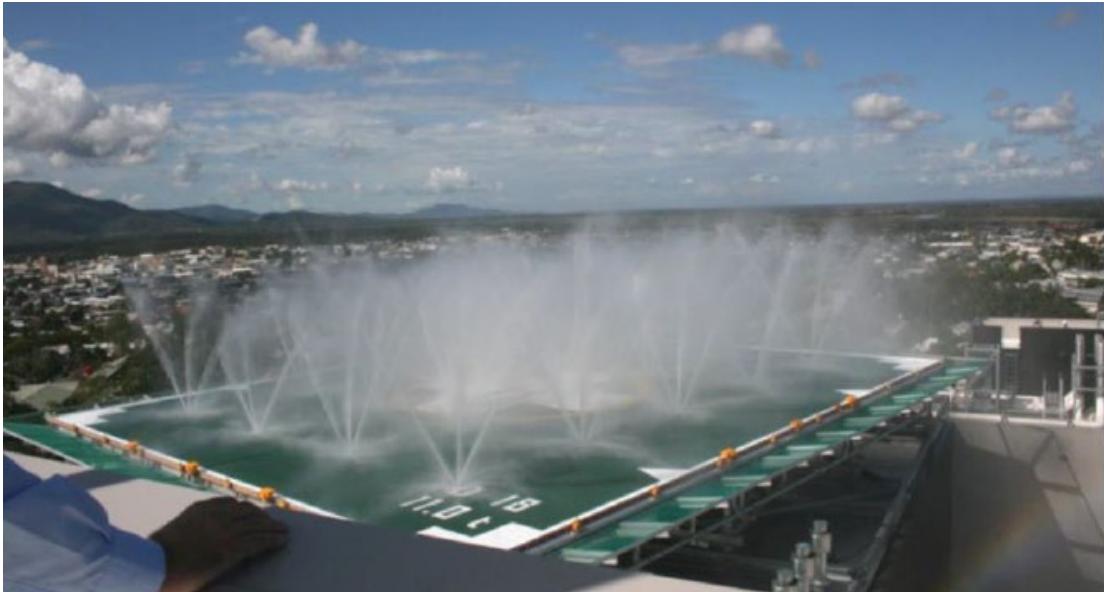
Figure II-6-8. A water-only DIFFS on a heliport with a passive fire-retarding surface
6.2.4.7 Complementary agents
6.2.4.7.1 Complementary agents should ideally be dispensed from one or two extinguishers, although more containers may be permitted when high volumes of the agent are specified, e.g. for H3 operations.
6.2.4.7.2 The discharge rate of complementary agents should be selected for the optimum effectiveness of the agent used. When selecting dry chemical powder for use with foam, compatibility should be ensured. Complimentary agents should comply with the appropriate specifications of the International Organization for Standardization (ISO).
6.2.4.8 Fire control time
6.2.4.8.1 A fire is deemed to be under control at the point when the initial intensity of the fire is reduced by 90 per cent. The helicopter operation, consistent also with a fixed wing operation, should achieve a 1-minute control time in the practical critical area using a quantity of primary extinguishing agent for initial attack, over an appropriate discharge duration, which is required for the continued control of the fire thereafter, and/or for possible complete extinguishment of the fire and which may have spread across the heliport operating area.
6.2.4.8.2 Speed of response has an important bearing on the effectiveness of escape in a survivable helicopter accident. Intuitively, a prompt intervention will likely bring the fire under control more quickly if firefighting primary extinguishing agent can be applied, at the full application rate, during the earliest stages of a fire’s development.
6.2.4.9 Summary of potential solutions
Table II-6-2 contains a summary of the firefighting solutions presented in Annex 14, Volume II, Chapter 6; a quick guide/key summary is provided in Table II-6-3.
Table II-6-2. Summary of firefighting options presented in Annex 14, Volume II
| Heliport type | Application method | Criticalarea assumptions | Dischargeduration | Primaryextinguishingagent | Responsetime objective |
| Surface level | Solid streamPFAS | FuselagedimensionsHO-H3 | 2 minutes | Level B/C foam | 2 minutes |
| Elevated | Solid streamFFAS/solid plate | FuselagedimensionsHO-H3 | 5 minutes | Level B/C foam | 15 seconds |
| Elevated/surface level | Dispersed patternsolid plate | TLOF +load-bearingFATO | 3 minutes | Level B/C foam | 15 seconds |
| Elevated/surface level | Dispersed patternpassive surface | TLOF +load-bearingFATO | 2 minutes | Water-only | 15 seconds |
Table II-6-3. Quick guide/key
| PFAS | Portable foam application system, e.g. hose-line, foam cannon on a rescue vehicle. |
| FFAS | Fixed foam application system, e.g. FMS, DIFFS, RMS. |
| Solid stream application | Foam delivered to a concentrated area in the form of a jet, e.g. foam monitors. |
| Dispersed pattern application | Foam delivered over a wider area from nozzles mounted in the deck surface, e.g. DIFFS. |
| Solid plate surface | Impervious to liquids. |
| Passive fire-retarding surface | Incorporates numerous drain holes to allow fuel (and other liquids) to drain through the surface. |
| Fire control time | The assumed fire control time in all cases is 1 minute from discharge of primary media at full application rate. |
| The application rate for a Performance Level B foam is 5.5 L/min/m². | |
The application rate for a Performance Level C foam and for water, is 3.75 L/min/m2.
6.2.5 Meeting the response time objective
6.2.5.1 The most important factors bearing on effective escape in a survivable helicopter accident at a heliport are the speed of initiating a response and the effectiveness of that response. The response time for heliports can be defined as the period that lapses between the occurrence of the incident or accident and the first application of primary extinguishing agent to the fire, except for a surface-level heliport where primary extinguishing agent is applied as a solid stream from an appropriately equipped rescue and firefighting vehicle. In this case, response time is measured from the initial call to the RFFS to the time when the first responding vehicles are in place to apply foam at a rate of at least 50 per cent of the required discharge rate.
6.2.5.2 For an FFAS located at an elevated heliport, the initial response should be comparatively quick because primary extinguishing agent-dispensing equipment will already be located adjacent to the scene of the incident (or accident) and 100 per cent discharge capability can be achieved in a relatively short space of time (up to 15 seconds after activation of the system). However, where it is necessary to move primary extinguishing agent-dispensing equipment to the scene of the incident or accident (i.e. a PFAS located on a vehicle), the response time is likely to be more protracted (up to 2 minutes in optimum conditions of visibility and surface conditions).
6.2.5.3 Applying a common timeline to a similar scale incident or accident, which occurs either on a confined-area heliport, using a FFAS, or at a remote surface level FATO, where intervention is via an appropriately equipped rescue vehicle (PFAS), it is reasonable to assume that the fire situation occurring in the first case will be brought under control, or even extinguished, before a PFAS is even on-scene at a remote FATO on a surface-level heliport (where a 2 minute response time objective in optimum conditions is permitted). This means that the confined-area heliport is very favourably positioned when considering the most important factors bearing on effective escape in a survivable helicopter accident: the speed of initiating the response and the effectiveness of that response.
6.2.5.4 In considering the response area at a heliport, all areas used for the manoeuvring, landing, take-off, rejected take-off, ground taxiing, air-taxiing and parking of helicopters that are in the direct control of the heliport operator should be considered. At a limited-sized heliport, including surface level, the response area will usually be the TLOF, and when load bearing, the FATO. However, if a heliport is served by one or more taxiways linking to stands, the heliport operator will have to consider rescue and firefighting arrangements for each additional element of the response area that is under their control.
6.2.5.5 At a surface-level heliport laid out in a similar way to a fixed wing airport, with a remote FATO serviced by a taxiway system linking to an apron with one or more stands, the rescue and firefighting response will normally be provided by a PFAS, i.e. a specialist vehicle, and in this case, following an alarm, firefighting and rescue equipment will be moved directly to the scene of the incident or accident.
6.2.6 Rescue arrangements
Rescue arrangements may include, but are not limited to, an assisted-rescue or self-rescue model predicated on the results of a risk assessment. Where a self-rescue model is promoted, it is especially important to establish the respective roles and interfaces between agencies on and off the heliport. This should form part of the heliport emergency plan and be periodically tested.
6.2.7 Communication and alerting system
6.2.7.1 A discrete communication system should be provided linking the rescue and firefighting service with central control and RFF vehicles (when provided). The mobilization of all parties and agencies required to respond to an aircraft emergency on a large heliport will require the provision and management of a complex communications system. The requirement is examined in the Airport Services Manual, Part 7 – Airport Emergency Planning, Chapter 12 (Doc 9137).
6.2.7.2 An alerting system for RFF personnel should be provided at their base facility and be capable of being operated from that location, at any other areas where RFF personnel congregate, and in the control tower (when provided). Examples include:
a) direct telephone line to the rescue control center or service room of the rescue personnel;
c) heat sensor for alarm and/or automatic switching of the extinguishing system; or
d) monitored video surveillance.
6.2.7.3 Further detailed guidance on communication and alarm requirements is detailed in the Airport Services Manual, Part 1 – Rescue and Fire Fighting, Chapter 4 (Doc 9137).
6.2.8 RFFS personnel
The provision of rescue and firefighting personnel should be determined using a task and resource analysis (see example TRA, Appendix A to Chapter 6). Depending on the rescue model employed (whether an assisted or self-rescue model), sufficient dedicated heliport rescue and firefighting personnel should be provided with appropriate training and with personal protective equipment (PPE) to enable them to perform their duties effectively.
6.2.8.2 Rescue equipment
6.2.8.2.1 Guidance on minimum equipment inventory required to ensure effective rescue arrangements are in place at the heliport are listed in Table II-6-4.
6.2.8.2.2 Equipment should only be used by personnel who have received adequate information, instruction and training.
Table II-6-4. Rescue equipment
| Adjustable wrench | 1 |
| Rescue axe, large (non-wedge or aircraft type) | 1 |
| Cutters, bolt | 1 |
| Crowbar, large | 1 |
| Hook, grab or salving | 1 |
| Hacksaw (heavy duty) and six spare blades | 1 |
| Blanket, fire resistant | 1 |
| Ladder (two-piece) * | 1 |
| Lifeline (5 mm circumference × 15 m in length) plus rescue harness | 1 |
| Pliers, side cutting (tin snips) | 1 |
| Set of assorted screwdrivers | 1 |
| Harness knife and sheath or harness cutters | ** |
| Man-Made Mineral Fibre (MMMF) Filter masks | ** |
| Gloves, fire resistant | ** |
| Power cutting tol** | 1 |
| * For access to casualties in an aircraft that may be on its side, the ladder should be of anappropriate length.** This equipment is required for each heliport crew member.*** Requires additional approved training by competent personnel. Equipment only specified forhelicopters with a D-value above 24m. | |
6.2.8.3 Personal protective equipment (PPE)
6.2.8.3.1 Depending on the rescue model employed (whether an assisted or self-rescue model), sufficient dedicated heliport rescue and firefighting personnel should be provided with appropriate training and with PPE to enable them to perform their duties effectively.
6.2.8.3.2 Specific outcomes from a task-resource analysis would determine whether there is a requirement for RFF personnel to be provided with PPE, or whether given the specific rescue model in use (e.g. self-rescue, fixed automatic system), PPE is not required.
6.2.8.3.3 All responding RFF personnel should be provided with appropriate PPE and respiratory protective equipment (RPE) to allow them to carry out their duties in an effective manner.
6.2.8.3.4 Personnel qualified to operate the RFF equipment effectively should be dressed in protective clothing prior to helicopter movements taking place. In addition, equipment should only be used by personnel who have received adequate information, instruction and training. PPE should be accompanied by suitable safety measures, e.g. protective devices, markings and warnings. The specifications for PPE should meet one of the international standards shown in Table II-6-5.
Table II-6-5. Standards for PPE
| Item | NFPA | EN | BS |
| Helmet with visor | NFPA 1971 | EN443 | BS EN 443 |
| Gloves | NFPA 1971 | EN659 | BS EN 659 |
| Boots (footwear) | NFPA 1971 | EN ISO 20345 | EN ISO 20345 |
| Tunic and trousers | NFPA 1971 | EN469 | BS EN ISO 14116 |
| Flash-hood | NFPA 1971 | EN13911 | BS EN 13911 |
6.2.8.3.5 Appropriate personnel should be appointed to ensure that all PPE is installed, stored, used, checked and maintained in accordance with the manufacturer’s instructions. Facilities should be provided for the cleaning, drying and storage of PPE when crews are off duty. Facilities should be well-ventilated and secure.
6.2.9 Means of escape
A minimum of two access/egress points should be provided to give occupants of a helicopter the option to escape upwind of a helicopter fire. The provision of an alternative means of escape is necessary for evacuation and for access by rescue and firefighting personnel. The size of an emergency access/egress route may require consideration of the number of passengers and of special operations like helicopter emergency medical services (HEMS) that require passengers to be carried on stretchers or trolleys.
Appendix A to Chapter 6
EXAMPLE OF A TASK/RESOURCE ANALYSIS (TRA)
Note.— For additional guidance on task/resource analysis, see Doc 9137 — Part 1, Chapter 10.5.
1. SCOPE
A task/resource analysis (TRA) describes the stages to be considered by a heliport operator and justifies the minimum number of qualified personnel needed to deliver an effective RFFS and deal with a helicopter incident/accident at the heliport.
2. PURPOSE
A risk-based approach that focuses on probable worst-case scenarios should be used where the purpose of the analysis is to identify the minimum number of personnel required to undertake identified tasks in real time, before supporting external services are on location able to assist the RFFS
3. CONSIDERATIONS
When conducting the analysis, consideration should be given to the types of aircraft using the heliport and the need for personnel to use PPE, RPE, hand lines, ladders and other rescue and firefighting equipment provided.
4. TASK ANALYSIS/RISK ASSESSMENT
A TRA should primarily consist of a qualitative analysis of the RFFS response to a realistic, worst-case aircraft incident scenario. The purpose should be to review the current and future staffing levels of the RFFS deployed at the heliport. The qualitative analysis may be supported by a quantitative risk assessment to estimate the reduction in risk. This risk assessment could be related to the reduction in risk to passengers and aircrew from deploying additional personnel. The impact of any pinch-points1 identified by the qualitative analysis must be assessed. The quantitative assessment should not be utilized to reduce the minimum number of RFFS personnel defined by the qualitative analysis.
5. PROCEDURE FOR WORKLOAD ASSESSMENT — PINCH-POINTS
5.1 If a pinch-point occurs when a task is critical to the success of the overall activity, the risk may be significantly increased. Workload assessment indicators are:
a) task criticality, i.e. the importance of the task to the success of the overall activity; and
b) task difficulty, defined in terms of:
-
(C) cues necessary to initiate or complete the task;
-
(T) time limitations imposed upon the staff to complete the task within a given window of time;
-
(P1) precision or skill required to undertake the task which, if excessive, could influence performance;
-
(M) mental demands, i.e the necessary skill and knowledge required from staff for a successful performance; and
-
(P) physical: demands upon staff due to heavy or sustained physical effort for successful task performance.
5.2 To evaluate the demands on each team member, the workload assessment indicators are rated for criticality or difficulty on a scale of one to three. An overall rating of three identifies pinch-points. The ratings are allocated as follows:
Table II-6-A-1. Workload assessment indicators
| Rating | Task criticality | Task difficulty |
| 1 | Not critical to overallsuccess of response. | Not difficult or not relevant to task. |
| 2 | Critical to success of sub-task. | Difficult but within capability of firefighter. |
| 3 | Essential for success of activity. | Very difficult causing loss of performance. |
6. WORKLOAD ASSESSMENT INDICATORS
6.1 The overall rating of a task is determined by the following rule: if a rating of 3 occurs in one or more of the ‘task difficulty indicators, the overall rating is assigned as 3, but only if the task criticality is also equal to 3. Otherwise, the overall rating takes the next highest value of the assessments for task difficulty (1 or 2) regardless of task criticality. This ensures that only tasks that are critical to the overall success are considered as potential pinch-points.
Note.— Although the result is numerical, it is indicative only of the relative effect of the task on overall performance. It enables comparisons to be made between different modes of personnel deployment or the use of different types of equipment or technique. A qualitative assessment is required.
6.2 A TRA and workload assessment should be used to identify the effectiveness of the current staffing level and to identify the level of improvement resulting from additional staffing. A worst-case scenario should be analysed to assess the relative effectiveness of at least two levels of RFFS staffing. The following items will assist in determining the basic contents of the analysis:
Note.— The list is not exhaustive and should only act as a guide.
a) description of heliport;
b) RFFS category;
c) response criteria;
d) current rate of movements;
e) operational hours;
f) current structure and establishment;
g) level of personnel;
h) level of supervision;
i) extraneous duties;
j) alerting system;
k) appliances and media availability;
l) specialist equipment;
m) medical facilities (role responsibility);
n) pre-determined attendance: local authority (police, fire and ambulance);
o) incident task analysis (worst case scenario, workload assessment, human performance);
p) appraisal of existing RFFS provision;
q) future requirements (heliport development and expansion); and
r) enclosures (maps, event trees etc.).
7. CONDUCT OF ASSESSMENT
7.1 The objective of RFFS is to save lives. The aim is to establish and maintain a team of competent personnel equipped with the required specialized equipment to provide an immediate response to an aircraft incident/accident to achieve that objective.
7.2 An assessment to establish the likely achievement of this aim should be conducted in a number of stages, each answering a specific question
Stage 1: Have the required tasks been identified that personnel should carry out?
The following tasks should be evaluated:
a) meet the required response time;
b) extinguish an external fire;
c) protect exit routes;
d) assist in self-evacuation;
e) extinguish an internal fire; and
f) rescue trapped personnel
Note.— The list is not exhaustive and should only act as a guide.
Stage 2: Has the team identified a selection of realistic accidents that could occur at the heliport?
This could be achieved by a statistical analysis of previous accidents at airports and heliports and by analysing data from both international and national sources. For example:
a) internal aircraft fire;
b) helicopter engine failure with a fire;
c) helicopter into helicopter with a fire; and
d) helicopter into terminal buildings with a fire.
Note.— All accidents/incidents should involve fire to represent worst-case scenarios.
Stage 3: Have the types of aircraft commonly in use at the heliport been identified?
This is important as the type of helicopters and their configuration have a direct bearing on the resources required in meeting Stage 1.
Stage 4: Has a worst-case location (in respect of the 4 km radius around the heliport reference point (HRP)) in which an aircraft incident could occur been identified?
To confirm the location of the worst-case scenario, a facilitator carries out this assessment using a team of experienced fire service personnel knowledgeable of the heliport and the locations in which an accident is likely to occur.
The team may have identified that the following factors contributed to a worst-case location:
travel time;
route to the accident site (hard or soft ground);
terrain, including surface conditions;
crossing active runways or FATOs;
aircraft congestion;
communications;
supplementary water supplies;
adverse weather conditions; and
additional lighting.
Stage 5: Has the complete incident (worst-case scenario) been developed by combining the incident types described in Stage 2, with the aircraft types identified in Stage 3 and the worst-case locations described in Stage 4?
Stage 6: Has the worst-case scenario been subject to a TRA in a series of table-top exercises?
Has the TRA and workload assessment been combined in a spreadsheet or matrix?
– Does the spreadsheet/matrix identify activities and sub-tasks in a logical sequence in real time?
Does the spreadsheet/matrix identify staff utilization and vehicle deployment (as required)?
Does the workload assessment identify task criticality, cues, time, precision, mental, physical and overall rating? Are they scored appropriately?
– Have any pinch-points been identified?
– Is there appropriate mitigation of the identified pinch-points?
8. ASSESSMENT CONCLUSION
Following this assessment, the applicant’s TRA is either acceptable or is required to address the issues raised in this assessment.
Appendix B to Chapter 6
CERTIFICATION STATUS (CRASHWORTHINESS)
1. BACKGROUND
1.1 The crashworthiness of a helicopter depends on:
a) revision status of the certification code at the time when the type certificate was issued;
b) modification status due to an operational requirement to apply certain standards; or
c) safety policy of the State or operator.
1.2 Features which could potentially limit the likelihood or extent of a post-crash fire or positively influence the outcome of a hard or emergency landing by improving occupant safety include:
a) seat design to ensure slower deceleration loads on occupants, i.e. energy attenuation seats;
b) occupant restraints;
c) crash resistant fuel systems (CRFS);
d) methods to minimize fuel egress through fuel tank vent, e.g. seal-sealing fuel lines; and
e) fuel lines that are designed, installed and constructed to be crash resistant.
Note.—The examples are from the FAA/EASA certification codes.
2. APPLICABILITY TO RISK ASSESSMENT
Where the population of helicopters is limited to those which have crashworthy features, this may be used by the State in the assessment for the required level of the services and personnel in the establishment of the RFFS policy.

没有要显示的评论
没有要显示的评论